
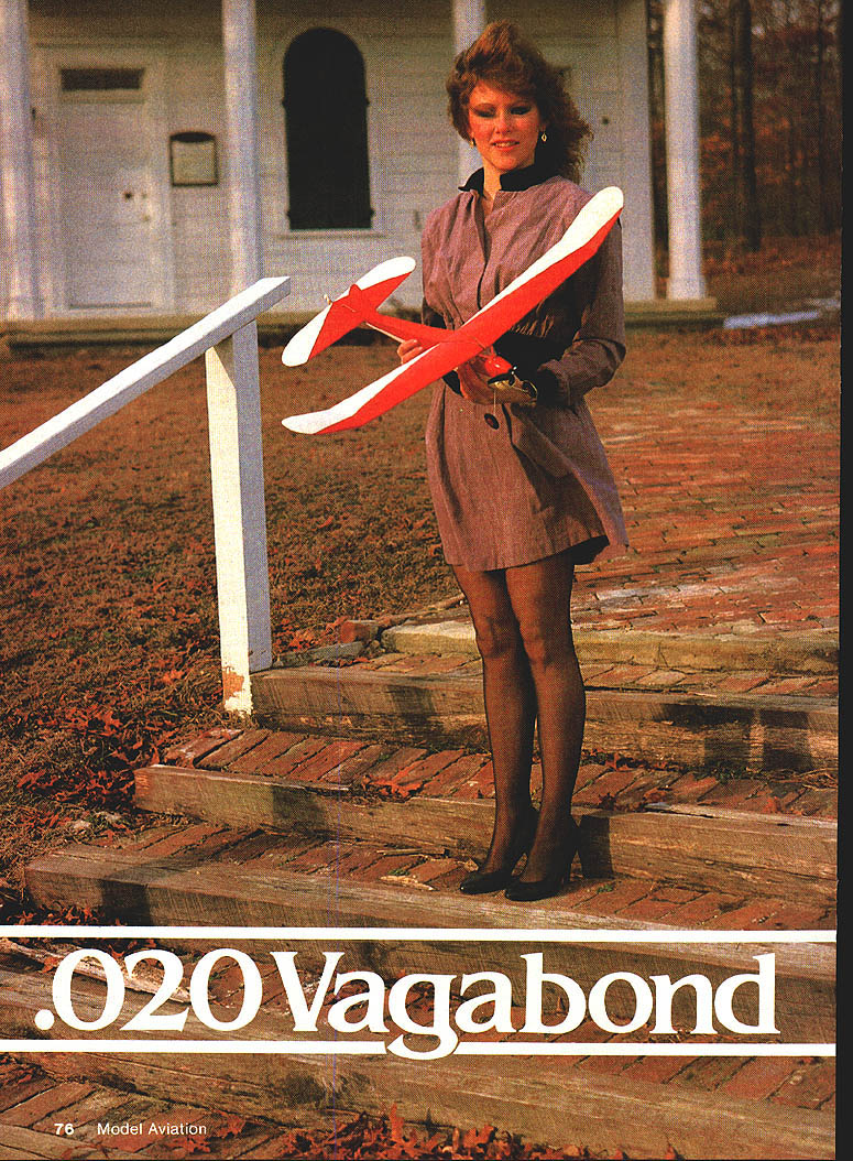
.020 Vagabond
Introduction
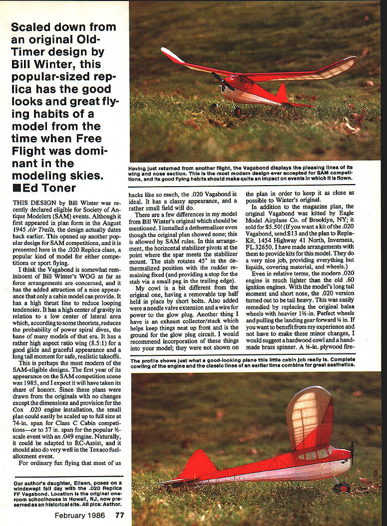
Scaled down from an original Old-Timer design by Bill Winter, the .020 Vagabond is a popular-size replica with the good looks and flying habits of a model from the era when Free Flight dominated the modeling skies. The design first appeared in plan form in the August 1945 Air Trails but predates that printing. It was recently declared eligible by the Society of Antique Modelers (SAM) and has appeared on the SAM competition scene since 1985.
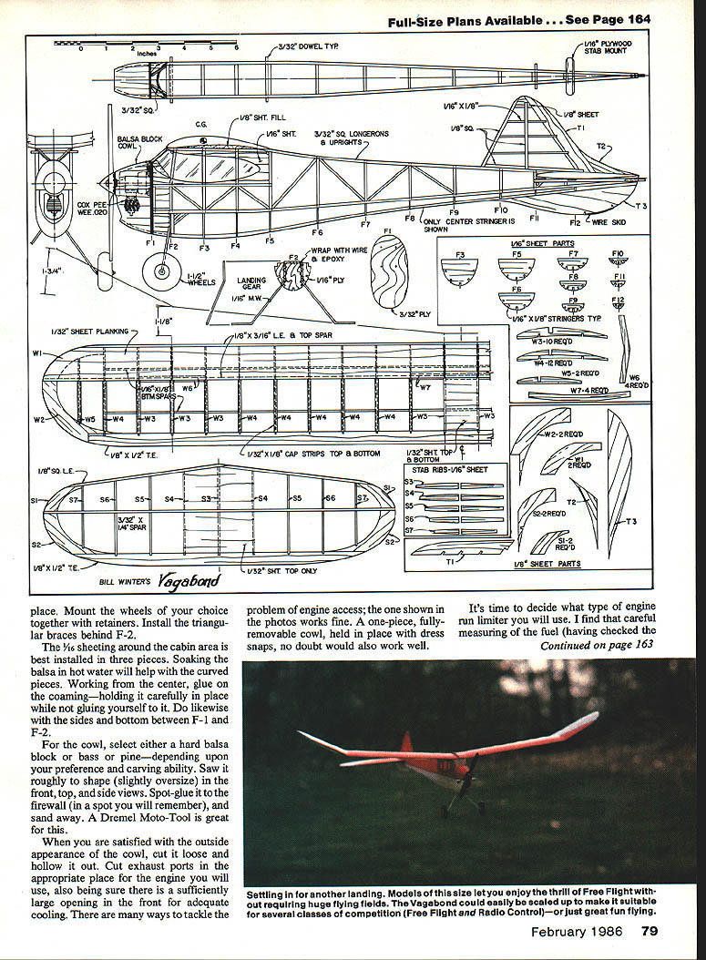
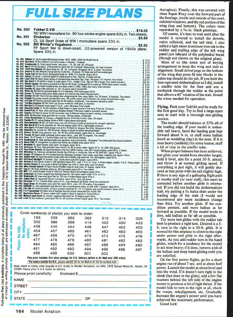
This article presents the .020 Replica class version — ideal for SAM competitions or sport flying. The small plan can be scaled up to a full-size 74 in. span for Class C Cabin or to 37 in. span for a 1/2-scale event with an .049 engine. It can also be adapted to RC-assist and should perform well in Texaco fuel-allotment events.
Design features
- High thrust line to reduce looping tendencies.
- High center of gravity relative to a low center of lateral area (said to reduce power-spiral dives).
- High aspect-ratio wing (8.5:1) for good glide and graceful appearance.
- Long tail moment for safe, realistic takeoffs.
- Typical behavior: climbs to the right under power and glides to the right afterward.
Modifications in this version
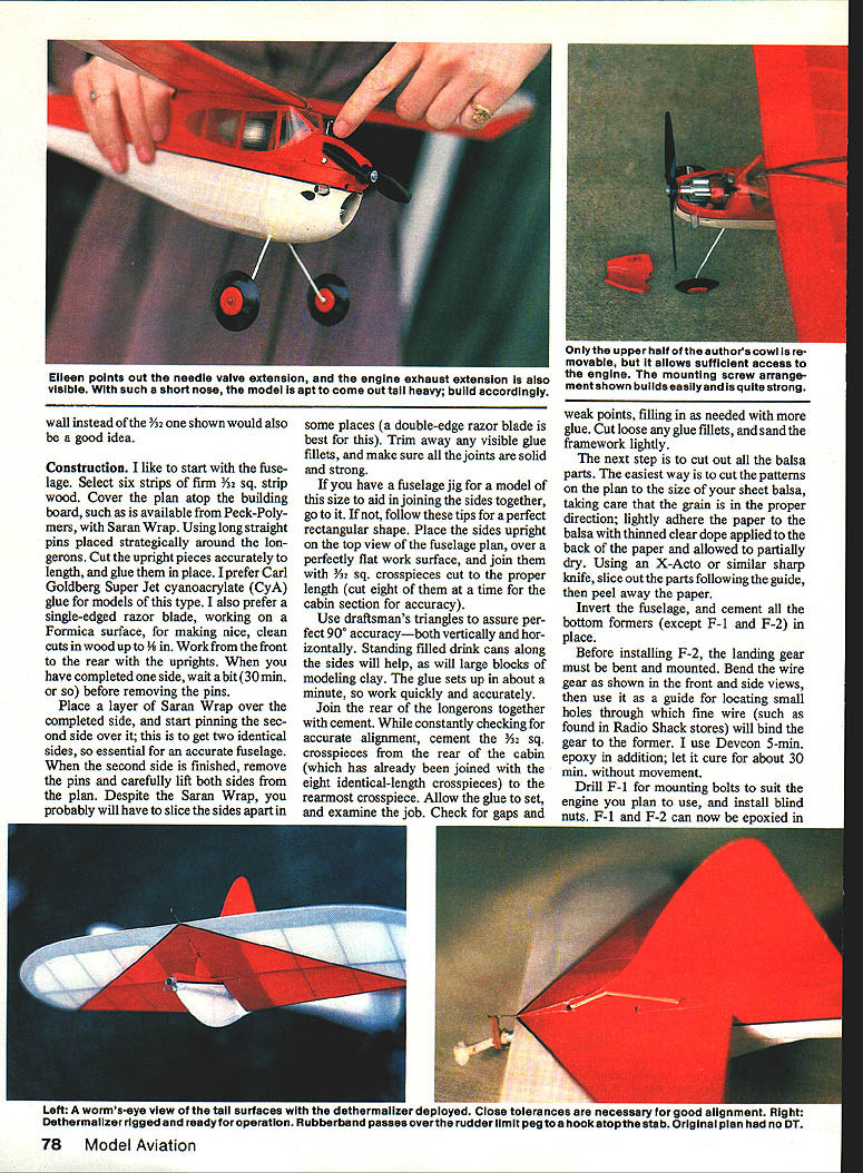
- Dethermalizer installed (allowed by SAM rules): stabilizer pivots where the spar meets the stabilizer mount and rotates 45° for the dethermalized position; rudder remains fixed and acts as a stop via a small peg in the trailing edge.
- Cowl with removable top held by short bolts.
- Needle-valve extension and wire for power to the glow plug.
- Exhaust collector/stack that helps keep the front neat and serves as a ground for the glow-plug circuit.
- Heavier 1-1/8 in. wheels and moving the landing gear forward 3/8 in. used to correct tail-heaviness in the .020 version.
- Recommendations (optional): hardwood cowl, handmade brass spinner, and 1/8-in. plywood firewall to help achieve proper balance without additional ballast.
Kits and plans
- The original Vagabond was kitted by Eagle Model Airplane Co., Brooklyn, N.Y., and sold for $5.50.
- To order a kit or the .020 Vagabond plan today, send $13 and the plan request to Repla-Kit, 1454 Highway 41 North, Inverness, FL 32650.
- Kits are well made; typical arrangements provide most wood and hardware. (Expect to supply covering material, wheels, and liquids yourself unless otherwise specified by the supplier.)
Construction
Fuselage
- Select six strips of firm 1/32" square strip wood for the longerons and uprights.
- Cover the plan on a flat building board with Saran Wrap over the plan.
- Pin long straight pins strategically around the longerons; cut upright pieces to accurate length and glue in place. Carl Goldberg Super Jet cyanoacrylate (CyA) is recommended.
- Use a single-edged razor blade on a Formica surface for clean wood cuts.
- When the front and rear uprights have been completed, wait about 30 minutes before removing the pins.
- Place a layer of Saran Wrap over the completed side and pin the second side over it to get two identical sides — essential for an accurate fuselage.
- Carefully slice the sides apart where necessary (a double-edge razor blade is best). Trim visible glue fillets and make sure all joints are solid and strong.
Joining the sides:
- Place the sides upright on the top view of the fuselage plan over a perfectly flat surface.
- Join them with 3/32" square crosspieces cut to proper length (cut eight at a time for the cabin section for accuracy).
- Use draftsperson's triangles to assure perfect 90° accuracy vertically and horizontally. Standing filled drink cans or blocks of modeling clay can help hold parts steady.
- Join the rear of the longerons together with cement and, while checking alignment, cement the 3/32" crosspieces from the rear of the cabin to the rearmost crosspiece.
- Allow glue to set, check for gaps and weak points, fill as needed, trim glue fillets, and sand the framework lightly.
Cutting balsa parts
- Cut patterns on the plan to the size of your sheet balsa, ensuring grain direction is correct.
- Lightly adhere paper patterns to the balsa with thinned clear dope on the back of the paper and let it partially dry.
- Using an X-Acto or similar sharp knife, slice out the parts and peel away the paper.
Bottom formers and gear installation
- Invert the fuselage and cement all bottom formers in place except F-1 and F-2.
- Bend the wire landing gear as shown on the plan (front and side views).
- Use the bent gear as a guide to locate small holes in F-2 through which fine wire will bind the gear to the former. Use Devcon 5-minute epoxy in addition and let cure about 30 minutes without movement.
- Drill F-1 for engine mounting bolts to suit the engine you plan to use, and install blind nuts.
- Epoxy F-1 and F-2 in place after the gear is mounted.
- Install triangular braces behind F-2.
Cowl
- Cowl construction recommendation: use a hard balsa block, bass, or pine depending on preference and carving ability.
- Saw roughly to shape (slightly oversize) in front, top, and side views. Spot-glue to the firewall in a remembered spot and sand to fit; a Dremel Moto-Tool works well.
- When satisfied with the exterior, cut the cowl loose and hollow it out. Cut exhaust ports for the engine and ensure a sufficiently large front opening for cooling.
- The version described uses a removable top half held with short bolts; a one-piece removable cowl fastened with dress snaps is also acceptable.
- Incorporate needle-valve extension, glow-plug power wire, and an exhaust collector/stack; add a ground glow-plug circuit if desired.
Wing and tail surfaces
- Construction is straightforward. Use cap strips on the wing if desired.
- Consider substituting basswood for balsa on the wing leading edge (it is forward of the CG and resists nicks).
- Select lightweight balsa for tail surfaces and the tail skid (T-3).
- If installing the dethermalizer as shown, eliminate the stabilizer center rib forward of the spar and add two half ribs so the stabilizer halves can pass downward over the fuselage from F-11 aft to the stab mount (see plan for dimensions). Omit the leading edge above the fuselage in that area.
Sheeting, coaming and cabin
- Install 1/16" sheeting around the cabin in three pieces; soaking the balsa in hot water helps form curved pieces.
- Working from the center, glue on the coaming, then the sides and bottom between F-1 and F-2.
- For cabin glazing use celluloid windows installed after covering.
Covering and finish
- Sand all framework smooth, taper edges, and remove burrs and glue build-ups.
- The described model was covered with lightweight white silk and finished with four coats of clear Aerogloss (tinted with red and white Aerogloss for color).
- Apply clear Super Poxy over the forward part of the fuselage, inside and outside of the cowl, celluloid windows, and the red portions of the wing (top and bottom).
- Separate colors with a 1/16-in. black pinstripe.
- Install dowels, cabin celluloid, and tail skid after covering.
- Optional additions: a light sheet-aluminum trim tab on the rudder and a trim tab on the trailing edge of the left wing just inboard of the polyhedral break (not shown on original plan).
Alignment and keys
- Use small dowel pegs on the bottom of the wing that pass into recesses in the cabin top to keep wing and stab alignment.
- If a fuselage-mounted dethermalizer is used, install a snuffer tube for the fuse and a toothpick through the rudder to allow a 45° rotation of the stabilizer. Install the necessary control and dethermalizer wires.
Engine and run-limiter
- Decide on an engine run-limiter method. The author prefers careful measuring of fuel after having checked running time on the ground with a stopwatch.
- Use a finely graduated syringe to measure fuel for consistent engine runs.
Flying and trimming
Initial balance and glides
- Target balance: 33% aft of the leading edge.
- If noticeably tail heavy:
- Bend the landing-gear legs forward about 1/4 in., or
- Stuff ballast (modeling clay) in the nose, or
- Use heavier wheels and pull the landing gear forward (the author used 1-1/8-in. Perfect wheels and moved the gear forward 3/8 in.).
- Alternatively, fit a hardwood cowl, brass spinner, and 1/8-in. plywood firewall to add nose weight without permanent ballast.
- If nose heavy, stuff a bit of clay in the snuffer tube.
- Test-glide procedure:
- From shoulder height, hold level, aim for a point about 50 ft ahead, and throw at normal gliding speed.
- Desired result: gentle descent reaching the point with a slightly high stall.
- If galloping or a mushy/near stall occurs, correct before further glides:
- Add a 1/32-in. ballast shim under the leading edge of the stab (do not exceed this unless necessary).
- If condition persists, add more ballast as far forward as possible.
- If the model tends to dive, add ballast farther aft as required.
Rudder and turn
- Bend the rudder tab to produce a right turn in hand-glides: desired turn is about 5–6 ft to the right over a 50-ft glide.
- Expect the airplane to climb to the right under power and glide to the right afterwards.
- As you increase rudder in hand-glides, watch for nose-heaviness; remove a little ballast if needed.
First power flights
- First flights: short engine runs of about 7 seconds at roughly half throttle.
- Launch level into the wind.
- If the model doesn't turn right in climb but does in the glide, add flat washers behind the left side of the engine mount to induce a bit of right thrust.
- If the model fails to turn right at all, check for warps and misalignment.
- Gradually increase engine power to achieve maximum performance.
Good luck!
Transcribed from original scans by AI. Minor OCR errors may remain.

