
1/2A 1938 BERRYLOID
George Niebauer
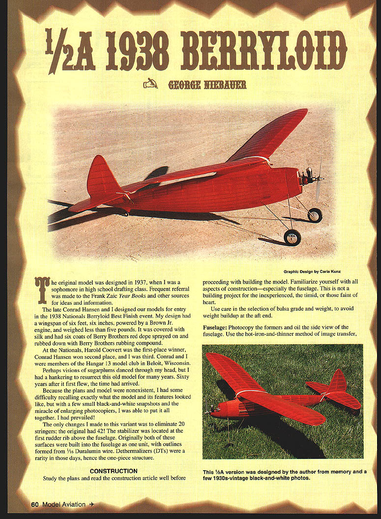
The original model was designed in 1937, when I was a sophomore in high school drafting class. Frequent referral was made to the Frank Zaic Year Books and other sources for ideas and information.
The late Conrad Hansen and I designed our models for entry in the 1938 Nationals Berryloid Best Finish event. My design had a wingspan of six feet, six inches, was powered by a Brown Jr. engine, weighed less than five pounds, was covered with silk and had six coats of Berry Brothers red dope sprayed on and rubbed down with Berry Brothers rubbing compound.
At the Nationals, Harold Coovert won first place, Conrad Hansen won second place, and I was third. Conrad and I were members of the Hangar 13 model club in Beloit, Wisconsin.
Perhaps visions of sugarplums danced through my head, but I had a hankering to resurrect this old model for many years. Sixty years after it first flew, the time had arrived. Because the plans and model were nonexistent, I had some difficulty recalling exactly what the model and its features looked like, but with a few small black-and-white snapshots and the miracle of enlarging photocopiers, I was able to put it all together.
The only change I made to this variant was to eliminate 20 stringers; the original had 42! The stabilizer was located at the first rudder rib above the fuselage. Originally both of these surfaces were built into the fuselage as one unit, with outlines formed from 1/16" Duralumin wire. Dethermalizers (DTs) were a rarity in those days, hence the one-piece structure.
CONSTRUCTION
Study the plans and read the construction article well before proceeding with building the model. Familiarize yourself with all aspects of construction—especially the fuselage. This is not a building project for the inexperienced, the timid, or those faint of heart. Use care in the selection of balsa grade and weight to avoid weight buildup at the aft end.
Type/specifications:
- Type: FF Texaco
- Wingspan: 54 inches
- Engine: 1/2A reed valve
- Flying weight: 20 ounces
- Construction: Built-up
- Covering/finish: Lightweight silk, butyrate dope
Fuselage
- Photocopy the formers and oil the side view of the fuselage. Use the hot-iron-and-thinner method of image transfer.
- Pin two of each keel piece (K-1, K-2, K-3) on the side view of the fuselage, one atop the other. Using large T-pins, push through both keels into your workboard. This is important because the pinholes in the plan and keels will be used to locate and align the keel when building the opposite fuselage half.
- Pin the top keel K-3 down, noting that it extends to the front of F-8, then continues from F-3 to F-0. Pin the bottom keels K-1 and K-2 down. Glue K-1 and K-2 together at the bottom groove with a scarf joint under F-4.
- Glue the former halves to the upper and lower keels, with the exception of the lower halves of F-1 through F-3 and the top of F-4 through F-7. Tack-glue the bottom of F-4 at the front of K-2. Former F-0 cannot be used now because it is one piece.
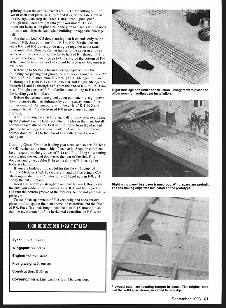
- Place and glue stringers as follows (refer to former numbering on the plan):
- Stringers 1 and 22: run from F-13 to F-8, then from F-3 through F-0.
- Stringers 2–8 and 21–15: run from F-13 and K-2 to F-0, full length.
- Stringers 9–11 and 14–12: run from the end of K-2 to F-5.
- Trim a 45° angle ahead of F-5 to facilitate continuing to F-0 after the landing gear is installed. Before gluing stringers permanently, sight down them to ensure straightness; cut away former material as necessary.
- As you build, trim the ends of K-1 and K-3 and stringers 6 and 17 at the front of F-0 to give a square firewall.
- After completing the first fuselage half, remove it, flip the plan over, align the pinholes in the keels with those in the plan, and build the opposite half in the same manner. Remove the plan and glue the halves together, leaving off K-1 and F-0 initially.
- Epoxy former doubler F-1a to the rear F-1 half with the groove facing aft.
For SAM (Society of Antique Modelers) 1/2A Texaco event using a Cox .049 engine:
- Drill four 3/32" holes for 2-56 blind nuts in F-0 and epoxy the nuts in place. Insert F-0 sideways, straighten, pull forward flush, and cut stringers as required.
Landing gear
- Form the landing gear struts and solder them. Solder a 1/4" OD washer to the inner side of the axle. Snap the completed landing gear into grooves F-1a and F-4.
- Using slow-setting epoxy, glue the second doubler to the rear former. Glue doubler F-1a and glue doubler F-4a to front F-4 using bolts and clamps while building the model.
- After landing gear installation, glue the remaining stringers and keels to F-0.
Pylon
- Carve the pylon from a block of 4–6 lb balsa, sized 1 3/4" x 2 1/2" x 10 5/8". Using a table saw, saw the block vertically in two. Glue together with paper between the halves and a few spots of model cement.
- Using a bandsaw, cut the block to the side-view shape. Trace the bottom and top exterior shapes and cut the bottom shape. Carve and blend into the top outline, leaving the sides vertical where they fit into the formers (see pylon sections on plan).
- Trace the interior bottom and top shapes, split the block apart, sand to retain 1/16" to 3/16" thickness maximum, then reassemble.
- Use a table saw to cut the dihedral angle into the top of each pylon half. Glue together permanently. Insert the pylon, checking the incidence against the thrustline, then glue permanently into the fuselage. Form the wing mount and glue in place.
Tail Block
- Make the tail block from soft balsa sized 1 1/2" x 1 3/8" x 1 3/4". Use lighter-density balsa than the pylon to avoid aft weight problems. Cut the block vertically in two and glue as with the pylon.
- Trace the side view and cut to shape. Trace the exterior shape of stringers 6 and 17 aft of F-13 (after they have been trimmed to 1/16" above the formers) to the bottom of the block. Trace the shape of F-13 to the front of the block after stringers 1–5 and 15 are in place. Trim stringers 18–22 flush with the top half.
- Trace the top of the block, saw to shape, carve the outside blending into the bottom where it meets stringers 6 and 17 and the top half of former F-13. Split the block apart, sand off the paper, hollow the inside as much as practical while maintaining strength, then glue together and to the fuselage.
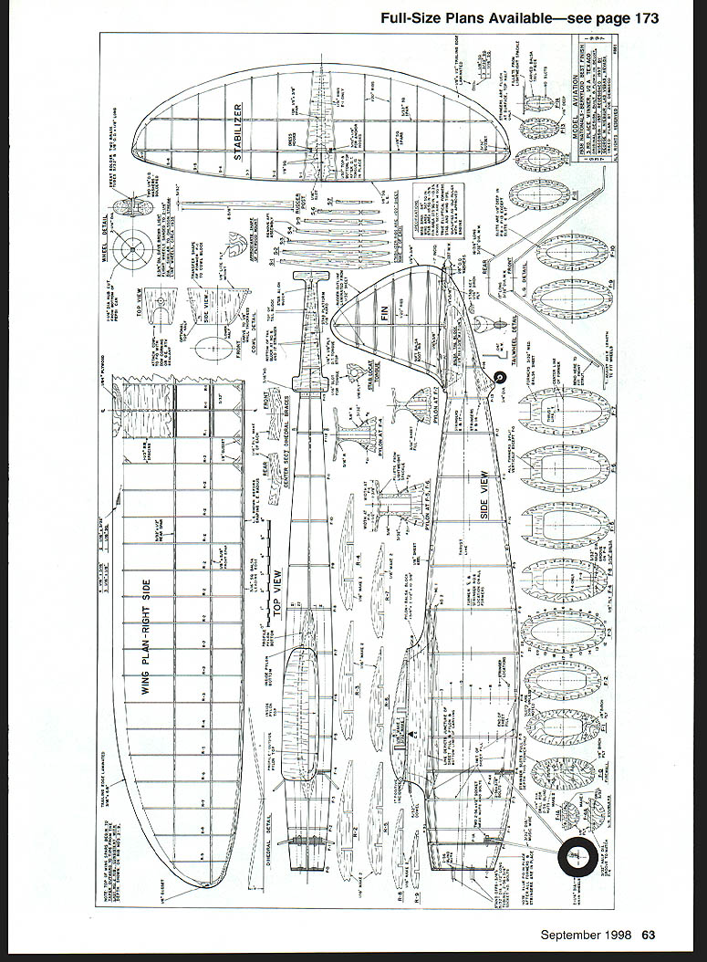
- Cut the stabilizer mount from hard 1/16" balsa. Glue it to the curved surface formed when cutting the side view to shape; this gives one degree of negative incidence built in. Shape the leading edge/DT stop and glue to the front of the stabilizer mount.
- Cut a 1/16" slot into the front of the stabilizer mount to accept the locating key; include a 1/16" plywood strip at the aft end of this slot, glued in place with epoxy.
- Add 1/16" sheet fill between the stringers around the front of the fuselage; use 3/32" sheet between the first four stringers at the top and bottom to maintain curvature. Plane and sand the fill and stringers to a smooth contour.
- Continue to the rear of the fuselage, allowing stringers to project 1/16" above the formers except at F-13 where they are flush. Use sanding sticks of varying radii to remove some former material between the stringers to prevent the covering from adhering.
- Form fillets from lightweight spackle with a little thinner added. Apply under the wing mount and the bottom of the pylon where it meets the sheet fill and stringers 1 and 22, and also under the stabilizer mount.
- Give the entire fuselage several coats of nitrate dope. If necessary, add 1/8" x 1/4" bracing between formers at their widest point to avoid crushing.
Pod and tail wheel:
- The tail wheel pod is made from lightweight balsa. Cut away the keel and stringers 10–13 between F-13 and F-14. Trim a block to fit between the formers and stringers 9 and 14, saw in half and glue together as with previous carvings, then carve the outside. Using lightweight balsa precludes extensive hollowing.
- Bend the axle/strut from .047" music wire to the shape shown on the plan. Place the strut in position on the pod and squeeze to create an indentation, glue the pod together, and add the 3/4" tail wheel.
Wheels:
- Freeze the wheels and sand/cut them to 2 1/2" diameter. Duplicate the profile shown on the drawing. Cut the hubs from a soda-can button by punching or drilling a hole at the centering point, scribing a 1 1/4" diameter circle, and cutting the hub out.
- Assemble the hubs to the brass bushings with washers and solder, avoiding prolonged heating to prevent melting the plastic wheel hubs.
Empennage
- Lightness is paramount. The stabilizer is conventional construction except for the laminated trailing edge. Cut a Masonite pattern from the last rib. Use thinned white glue and large T-pins to hold the strips in place while drying. Position the 1/32" sheet on the bottom center section after the structure is built.
- Glue two 1/8" square pieces of balsa behind the leading edge. Cut a 1/16" slot long enough for the stabilizer locating tongue; make it a tight fit to ensure a 45° DT angle. If the angle is not steep enough, sand a small amount from the nub on the locating tongue. Epoxy in place after verifying the angle.
- The fin has laminated edges. Cut a Masonite template, assemble the ribs in strips, shape to a streamlined airfoil after drying, and glue the fin in place. Fit the soft balsa root rib and cement. Form fillets where the fin joins the stabilizer, as on the wing and stabilizer roots.
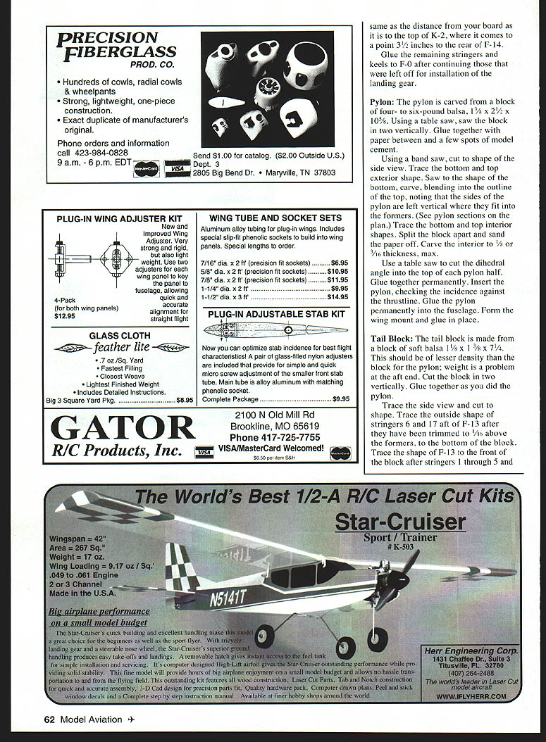
Wing
- The wing has a laminated trailing edge. Cut a Masonite template of the trailing edge from the last rib R-2 out to the tips. You can laminate the entire trailing edge from tip to center section, or make the straight portion from tapered stock for simplicity.
- Cut 1/16" notches for the ribs. Note that the tops of the spars taper consistently with their depth in the ribs, beginning with rib R-3. Soak the 1/4" square leading edge stock and pin it in place to dry before gluing.
Finishing Up
- Downthrust and right thrust may be incorporated into standoffs by making them shorter.
- The DT limit line is made from heavy monofilament fishing line, lightweight braided metal fishing leader, or control-line leadout wire. Form a loop at each end small enough to be forced over the washers on the DT hooks but not to slip off easily. Make sure the line is long enough to give a 45° stabilizer angle.
- Key the wing to its mount by gluing the keys to the bottom of the spars.
Flying
- Balance the model at 35% chord—4 7/8 inches ahead of the trailing edge. My model required some nose weight to achieve proper balance. Washin (3/8") was built into the port tip.
- The first flight had a rich needle-valve setting and went out of sight. Subsequent flights improved with a leaner needle-valve setting, but the climb-out was too dramatic for 1/2A Texaco competition; tame the climb for maximum performance in that event.
If you choose to build my recollection of this scaled-down model, I'm certain you will feel rewarded with a sense of accomplishment not felt every day in a modeler's life.
George Niebauer 1405 E. Vegas Valley Dr. #281 Las Vegas, NV 89109
Sources
- Lightweight spackling for fillets:
- Patch-N-Paint
- Custom Building Products
- Seal Beach, CA
- (310) 598-8808
- Lite Flite wheels, main wheels:
- Dave Brown Products Inc.
- 4560 Layhigh Rd.
- Hamilton, OH 45013
- Smooth-contour wheels, tail wheel:
- Williams Bros.
- 181 Pawnee St.
- San Marcos, CA 92069
Transcribed from original scans by AI. Minor OCR errors may remain.

