
1/2A Arrow
Barry Baxter
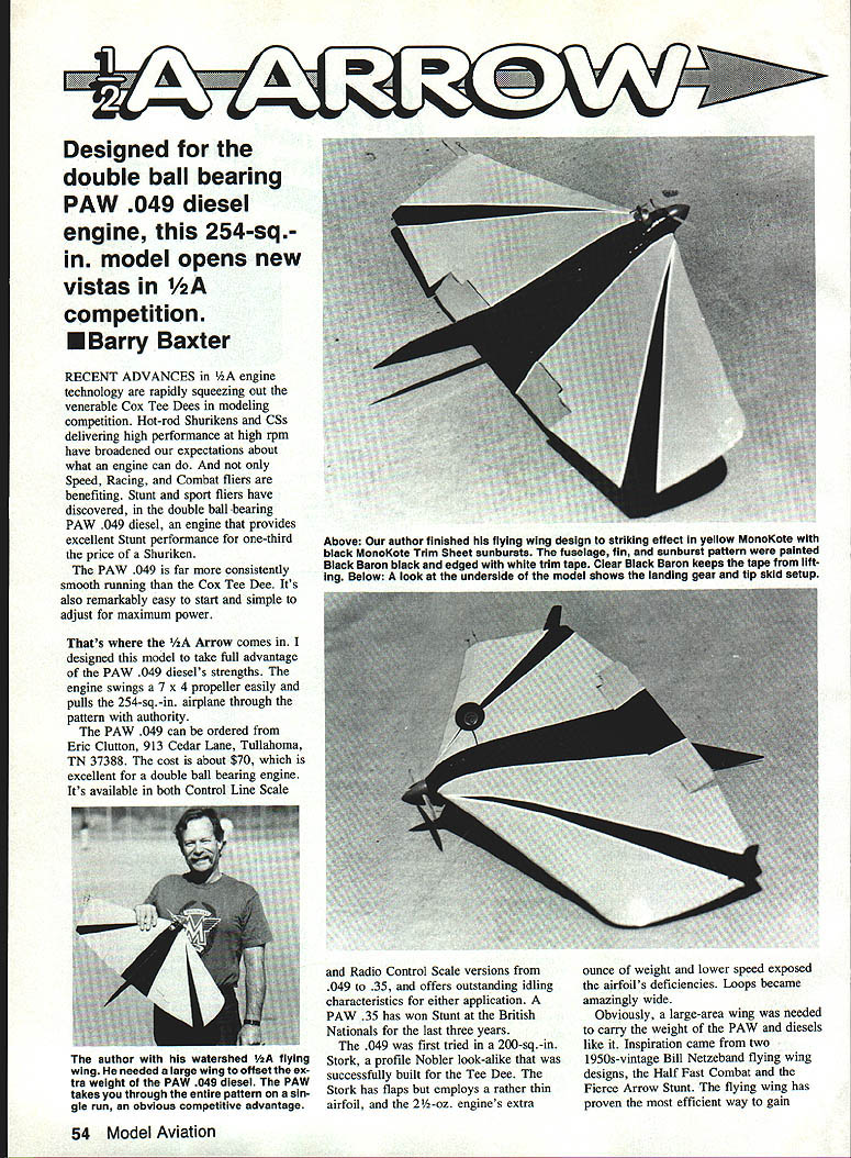
Designed for the double ball-bearing PAW .049 diesel engine, this 254 sq. in. model opens new vistas in 1/2A competition.
Recent advances in 1/2A engine technology are rapidly squeezing out the venerable Cox Tee Dees in modeling competition. Hot-rod Shurikens and CSs delivering high performance at high rpm have broadened expectations about what an engine can do. Not only Speed, Racing, and Combat fliers are benefiting — stunt and sport fliers have discovered, in the double ball-bearing PAW .049 diesel, an engine that provides excellent stunt performance for a fraction of the price of a Shuriken.
The PAW .049 is far more consistently smooth running than the Cox Tee Dee. It is also remarkably easy to start and simple to adjust for maximum power. The PAW swings a 7x4 propeller easily and pulls the 254 sq. in. airplane through the pattern with authority.
The PAW .049 can be ordered from Eric Clutton, 913 Cedar Lane, Tullahoma, TN 37388. The cost is about $70, which is excellent for a double ball-bearing engine. It is available in both control-line and radio-control versions from .049 to .35, and offers outstanding idling characteristics for either application. A PAW .35 has won Stunt at the British Nationals for the last three years.
Because the PAW barely sips fuel, it will run about 10 minutes on one ounce of fuel. I use Red Max Fuel, available from FHS Supply, Inc., 239 Bethel Church Rd., Clover, SC 29710. The company mixes it to my recipe of 35% ether, 20% castor, 1.5% amyl nitrate, balance kerosene. This brew has worked quite well in all diesel sizes. Diesel sizes and the current nitro shortage give diesel fuel the additional advantages of availability and stable price.
Because of their slower, higher-torque characteristics, diesel engines deliver a power band that lends itself much better to stunt flying than high-rpm glow engines. Most current glow engines have been modified to provide this sort of power.
On its first flight the 1/2A Arrow exceeded my highest expectations. The only flaw was a slight twist in the wing, which I removed with a heat gun. Test flown at sea level and again at 5,000 ft., the model flew the pattern at both altitudes. At high altitude, however, the 7x4 prop was too much; the little engine lost rpm through the maneuvers. Substituting a 7x3 propeller would make the engine more efficient at that height. The PAW .049 starts and runs on the same compression setting; little tuning is required once the initial settings are found. For high-altitude operation the compression screw is turned about one-eighth turn and the needle valve adjusted to a leaner setting.
Construction
Building a model — or indeed a full-size craft — from a working drawing is fraught with difficulties. Usually you build an airplane, fly it, draw the results, and then take time to redraw the airplane. I did the other way around and, sure enough, the need to make changes led to some peculiar building techniques. I've since worked out an efficient method, described in the instructions that follow. Begin by cutting out all parts to make a kit.
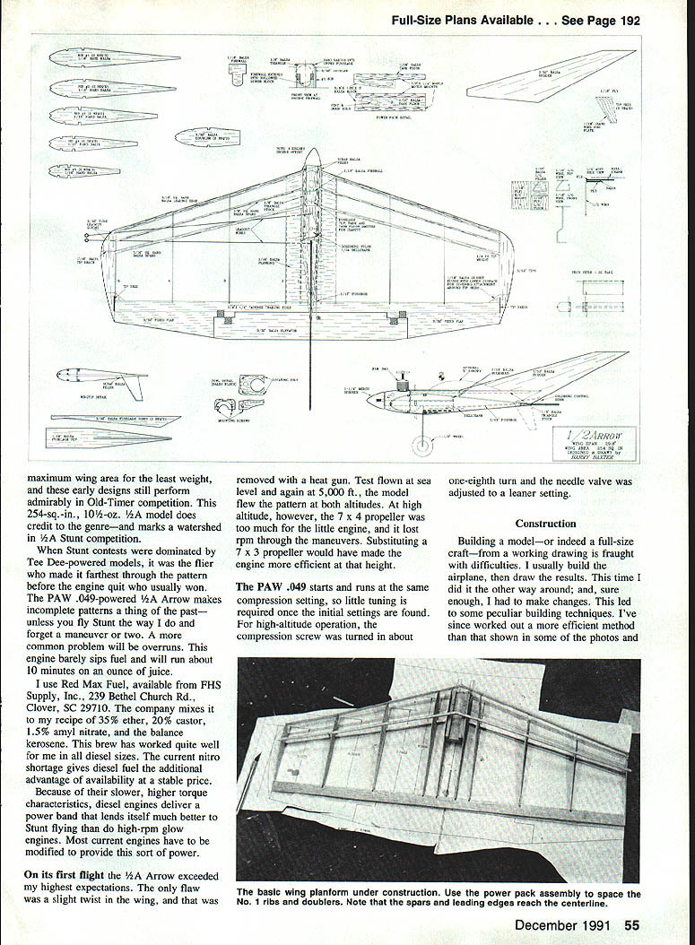
Wing
- Use 1/16" hard balsa, at least for the No. 3 and No. 4 ribs. Since these ribs are unsupported for much of their length, they can become distorted when the covering material is shrunk.
- Draw engine-mount reference lines on the doublers to ensure alignment when the mounts are installed.
- Assemble the wing planform, allowing the leading edge and 1/16" spars to join at the centerline. They will be trimmed back later. Leave the No. 1 ribs and doublers loose until the power-pack assembly and bellcrank mount are ready to install.
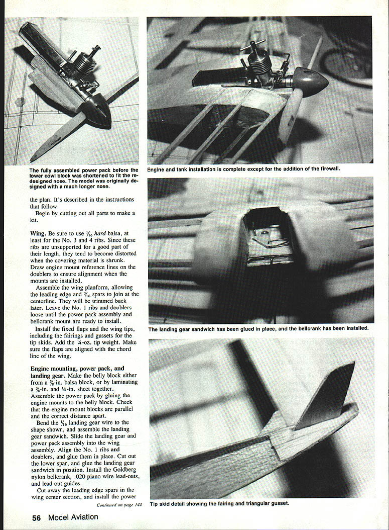
- Install the fixed flaps and the wingtips, including the fairings and gussets for the tip skids. Add 1/4 oz. tip weight. Make sure the flaps are aligned with the chord line of the wing.
Engine mounting, power pack, and landing gear
- Make the belly block either from a 5/8 in. balsa block or by laminating 3/8 in. and 1/4 in. sheets together.
- Assemble the power pack by gluing the engine mounts to the belly block. Check that the engine-mount blocks are parallel and the correct distance apart.
- Bend 1/16" landing-gear wire to the shape shown on the plan and assemble the landing-gear sandwich.
- Slide the landing gear and power-pack assembly into the wing assembly. Align the No. 1 ribs and doublers, and glue the planform.
- Cut out the lower spar and glue the landing-gear sandwich in position.
- Install the Goldberg nylon bellcrank, .020" piano-wire lead-outs, and lead-out guides.
- Cut away the leading-edge spars in the wing center section and install the power-pack assembly. Note that the No. 1 ribs, doublers, spars, and leading edges reach the centerline when fully assembled.
- Make sure the engine mounts are aligned on the wing chord and butted up to the landing-gear sandwich assembly. Slip the sides of the engine mounts with scrap balsa so that the nose can be faired into the spinner.
- Install the 1/8" wire pushrod; add the tank floor and bulkheads. Plank the upper and lower center section. Install the fuel tank.
Tail surfaces
- Hinge the elevator. I used Goldberg nylon hinges. Rather than merely cutting a slot in the elevator and trailing edge, cut shallow notches in both surfaces where the hinges will be mounted. After installing the hinges, fill the notches with Model Magic.
- Install the control horn (included with the bellcrank) and attach the pushrod.
- Glue on the fin. Add the fuselage sides, triangular fillers, and top.
Engine installation
- Note the engine offset. I have been experimenting with a concept favored by foreign combat fliers who use significant engine offset — but no rudder offset — in a straight airframe. The straight fin keeps the airframe aligned with the flight path and the offset thrust maintains line tension. The combination works well on this model.
- Make the cowl from a solid block or use laminated pieces. Carve and sand it to shape. Sand the rest of the model to the cross sections shown, paying particular attention to rounding the leading-edge spars.
- The cowl is held on by small wood screws at the front. Keep the rear alignment pins short so the cowl can be removed with the prop and spinner in place.
- I used a 1-1/4 in. Merco spinner, which can be difficult to find here. If you cannot locate the Merco, reshape the nose to accommodate a 1-1/2 in. spinner. Extra scrap material will be required on the right side of the engine mounts to fair in the larger spinner; do not reduce the engine offset to accomplish this.
Covering and finishing
- Choose your covering material carefully. Many plastic heat-shrinkable materials will shrivel from diesel fuel. I have tried several with poor results and have had good luck only with MonoKote and Micafilm.
- An alternative is to use old-fashioned dope finishes over the covering material of your choice. Fuelproof paint is not required.
- Cover the model and install the tip fillers.
Flying
Balanced at the center-of-gravity (CG) location shown on the plan, the 1/2A Arrow will be stable yet highly responsive. Moving the CG aft makes the model a bit twitchy.
Performance is excellent, with no surprises. On 35 ft., .012-in. lines it is an outstanding stunt flier. For the ultimate in high-speed performance — and a great combat machine — leave off the upper fuselage section and landing gear, and add a Shuriken.
If you prefer even more torque, drop a DC Sabre .09 diesel into the mounts. Move the firewall rearward to accommodate the longer, heavier engine while keeping the nose length unchanged to maintain the CG — and enjoy the extra power.
Diesel engines have begun to catch on with the country's RC fliers; Eric Clutton is having difficulty maintaining inventory of the RC versions. The control-line fraternity won't be far behind. If you are interested in ease of operation, fuel economy, and smooth, torquey power, diesels are the way to go.
For 1/2A stunt competition or sport flying, the Arrow is hard to beat. Power it with a diesel, and be prepared to be amazed by how carefree small models can be both to operate and to fly.
Transcribed from original scans by AI. Minor OCR errors may remain.

