
1/2A Miss America
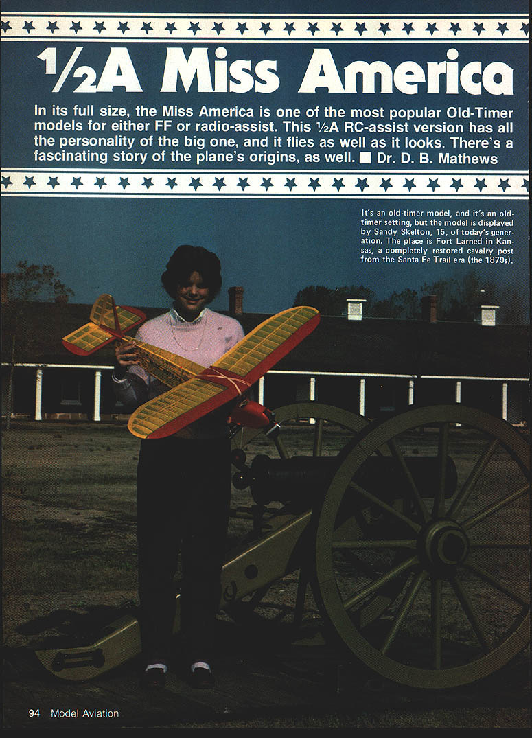
In its full size, the Miss America is one of the most popular Old-Timer models for either free flight or radio-assist. This 1/2A RC-assist version has all the personality of the big one, and it flies as well as it looks. There's a fascinating story of the plane's origins, as well. — Dr. D. B. Mathews
I was looking at an October 1936 copy of Model Airplane News from my collection. Among the items listed under Charles Hampson Grant's name as editor on the contents page are:
- "Building the T-D Coupe"
- "Gas Lines"
- "Ways and Means of Gas Model Success," by Joe Kovel
- "How to Build and Fly the SOC-1 Scout," by Bill Winter
- "A Soaring Glider," by Alan Orthof
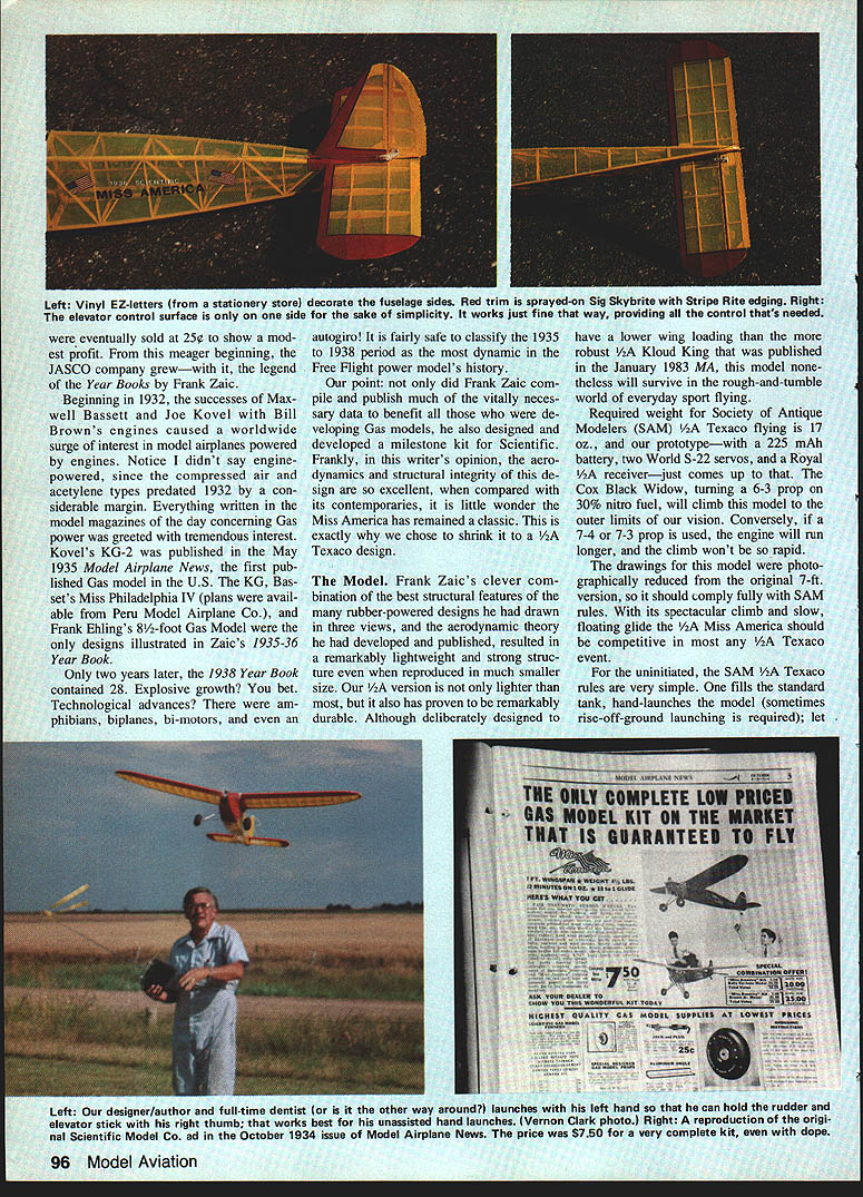
Across from the contents page is an ad from Scientific Models, 218-220 Market St., Newark, N.J. The feature of that ad (and others like it which ran for many years) is the subject of this article. The top half of that ad is for the new Miss America kit. The large type banner states: "The only complete low-priced Gas Model kit on the market that is guaranteed to fly ... Now everyone can afford to build a gas model easily and efficiently." The kit had been introduced in July 1936.
Nowhere in any ad for the Miss America that I can find is the designer's name mentioned. This is not peculiar to just this kit, however. Berkeley Model Supplies' ad has no mention of Ben Shereshaw as the designer of the Cavalier or Bill Effinger of the Buccaneer. No credits are shown for the Modelcraft Corbin and Scout, Burd's King Burd, nor Aircraft Industries' California Chief.
Incredibly, those were the only gas models advertised in that issue. More engines than models were shown. Forster Little Hercules, Brown Junior, Bunch Mighty Midget, Fergusson Condor, Baby Cyclone, and even G.H.Q. ads were included, but kits for those newfangled gas models were few and far between.
Obviously, the Miss America was a very early kit in a many to follow of what we now call Antiques and Old-Timers. To imply a guarantee of flight was very novel to say the least! Scientific Models was placing a lot of faith in the design and development work by Frank Zaic. They had good reason: Zaic had already established himself as one of the hobby's premier engineers and chronologist of scientific progress with his classic Junior Aeronautics Year Books.
Frank Zaic and his brother, John, had been building models since 1926. Of modest means, the brothers first published a Model Airplane Guide and Log Book in 1932. This was a combination of ruled pages for recording flights and observations, together with plans and helpful hints. Although the brothers sold a few copies, the income was less than handsome. Frank continued to work as a draftsman for patent attorneys, but as the Depression came on, less and less work was available—giving him more time to work on a 1933 version. This was printed by the brothers in their modest flat for a total cost of $17.00, and enough copies were eventually sold to show a modest profit. The meager beginning grew into the JASCO company with the legend of the Year Books.
Beginning in 1932, successes by Maxwell Bassett, Joe Kovel and Bill Brown's engines caused a worldwide surge of interest in model airplanes powered by engines. (Notice I didn't say "engine-powered," since compressed-air and acetylene types predated 1932 by a considerable margin.) Everything written in the model magazines of the day concerning gas power was greeted with tremendous interest. Kovel's KG-2, published May 1935 in Model Airplane News, was the first published gas model in the U.S. Bassett's Miss Philadelphia IV plans were available from the Peru Model Airplane Co. Frank Ehling's 8-foot gas model designs were illustrated in Zaic's 1935–36 Year Book. Only two years later the 1938 Year Book contained 28.
Explosive growth between 1935 and 1938—technological advances, amphibians, biplanes, bi-motors and autogiros—make the 1935–1938 period fairly safe to classify as the most dynamic in free-flight power-model history up to that point. Frank Zaic compiled and published much vitally necessary data to benefit developing gas models. He also designed and developed the milestone kit for Scientific Models. Frankly, in the writer's opinion, the aerodynamics and structural integrity of the design were excellent compared to its contemporaries; little wonder the Miss America has remained a classic. Exactly why I chose to shrink the 1/2A Texaco design follows.
The Model
Frank Zaic's clever combination of the best structural features of many rubber-powered designs he had drawn in three views, and the aerodynamic theory he had developed and published, resulted in a remarkably lightweight and strong structure even when reproduced in much smaller size. Our 1/2A version is not only lighter than most, but it also has proven to be remarkably durable. Although deliberately designed to have a lower wing loading than the more robust 1/2A Kloud King that was published in the January 1983 MA, this model nonetheless will survive in the rough-and-tumble world of everyday sport flying.
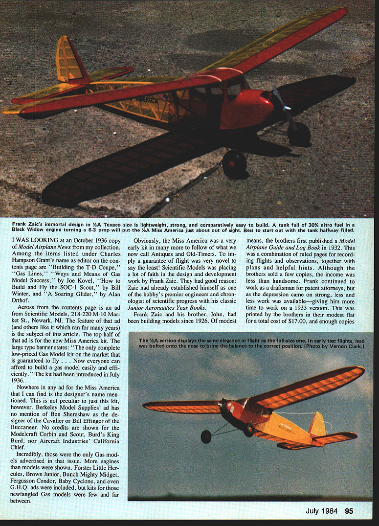
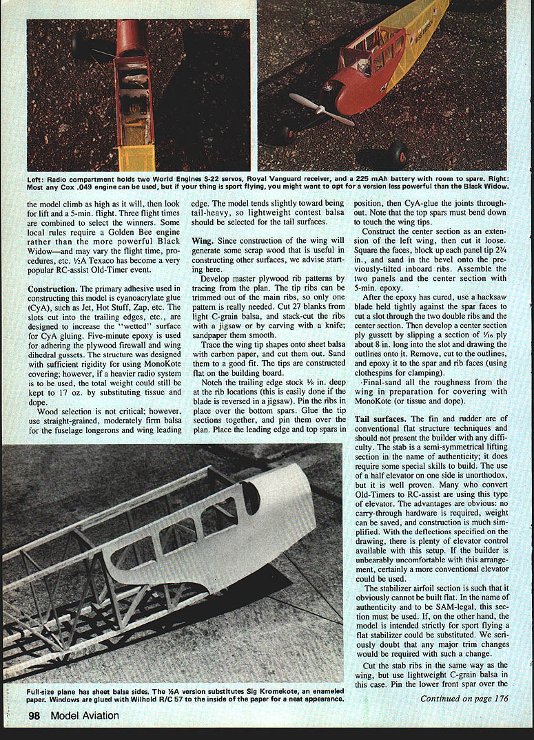
Required weight for Society of Antique Modelers (SAM) 1/2A Texaco flying is 17 oz, and our prototype—with a 225 mAh battery, two World S-22 servos, and a Royal 1/2A receiver—just comes up to that. The Cox Black Widow, turning a 6-3 prop on 30% nitro fuel, will climb this model to the outer limits of our vision. Conversely, if a 7-4 or 7-3 prop is used, the engine will run longer, and the climb will not be so rapid.
The drawings for this model were photographed reduced from the original 7-ft. version, so it should comply fully with SAM rules. With its spectacular climb and slow, floating glide the 1/2A Miss America should be competitive in most any 1/2A Texaco event.
For the uninitiated, the SAM 1/2A Texaco rules are very simple. One fills the standard tank, hand-launches the model (sometimes rise-off-ground launching is required); let the model climb as high as it will, then look for lift and a 5-minute flight. Three flight times are combined to select the winners. Some local rules require a Golden Bee engine rather than the more powerful Black Widow—and may vary the flight time, procedures, etc. 1/2A Texaco has become a very popular RC-assist Old-Timer event.
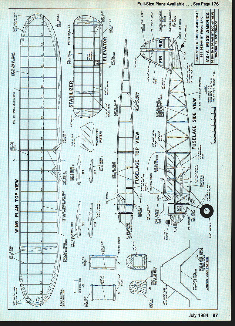
Plans and Drawings
Designed by Frank Zaic Tracing by Joe DeMarco
Plan views and patterns included:
- Wing plan top view
- Stabilizer
- Elevator
- Windscreen pattern
- Fuselage top view
- Fuselage side view
- Fin/rudder
- Landing gear pattern
Construction
The primary adhesive used in constructing this model is cyanoacrylate glue (CyA), such as Jet, Hot Stuff, Zap, etc. The slots cut into the trailing edges, etc., are designed to increase the "wetted" surface for CyA gluing. Five-minute epoxy is used for adhering the plywood firewall and wing dihedral gussets. The structure was designed with sufficient rigidity for using MonoKote covering; however, if a heavier radio system is to be used, the total weight could still be kept to 17 oz. by substituting tissue and dope.
Wood selection is not critical; however, use straight-grained, moderately firm balsa for the fuselage longerons and wing leading edge. The model tends slightly toward being tail-heavy, so lightweight contest balsa should be selected for the tail surfaces.
Wing
Since construction of the wing will generate some scrap wood that is useful in constructing other surfaces, we advise starting here.
Develop master plywood rib patterns by tracing from the plan. The tip ribs can be trimmed out of the main ribs, so only one pattern is really needed. Cut 27 blanks from light C-grain balsa, and stack-cut the ribs with a jigsaw or by carving with a knife; sand them smooth.
Trace the wing tip shapes onto sheet balsa with carbon paper, and cut them out. Sand them to a good fit. The tips are constructed flat on the building board.
Notch the trailing edge stock 1/8 in. deep at the rib locations (this is easily done if the blade is reversed in a jigsaw). Pin the ribs in place over the bottom spars. Glue the tip sections together, and pin them over the plan. Place the leading edge and top spars in position, then CyA-glue the joints throughout. Note that the top spars must bend down to touch the wing tips.
Construct the center section as an extension of the left wing, then cut it loose. Surface the faces, block up each panel tip 2-3/4 in., and sand in the bevel onto the previously tilted inboard ribs. Assemble the two panels and the center section with five-minute epoxy.
After the epoxy has cured, use a hacksaw blade held tightly against the spar faces to cut a slot through the two double ribs and the center section. Then develop a center section plywood gusset by slipping a section of 1/16 in. plywood into the slot and drawing the outlines onto it. Remove, cut to the outlines, and epoxy it to the spar and rib faces (using clothespins for clamping).
Final-sand all the roughness from the wing in preparation for covering with MonoKote (or tissue and dope).
Tail Surfaces
The fin and rudder are of conventional flat-structure techniques and should not present the builder with any difficulty. The stabilizer is a semi-symmetrical lifting section in the name of authenticity; it does require some special skills to build. The use of a half elevator on one side is unorthodox, but it is well proven. Many who convert Old-Timers to RC-assist are using this type of elevator. The advantages are obvious: no carry-through hardware is required, weight can be saved, and construction is much simplified. With the deflections specified on the drawing, there is plenty of elevator control available with this setup. If the builder is uncomfortable with this arrangement, certainly a more conventional elevator could be used.
The stabilizer airfoil section is such that it cannot be built flat. In the name of authenticity and to be SAM-legal, this section must be used. If, on the other hand, the model is intended strictly for sport flying, a flat stabilizer could be substituted. We seriously doubt that any major trim changes would be required with such a change.
Cut the stab ribs in the same way as the wing, but use lightweight C-grain balsa in this case. Pin the lower front spar over the plan, then shim the leading edge, trailing edge, and rear lower spar to the proper height with scrap balsa. Notice that the bottom spars extend under the sheet tips. Add the ribs. Fill the tips with scrap balsa.
Remove the unit from the building surface, and carefully cut a 3/16-in. slot vertically for the elevator spar. Add secondary reinforcement ribs and gussets, then cut the elevator loose. Hinge with Du-Bro 1/2A molded hinges or Ace nylon sheet units.
Trial-fit the fin into the stab slot, adjusting for a snug fit. Be sure the rudder will not bind against the elevator. Sand both units to smooth contours, and cover them.
Fuselage
Cut out the plywood sides directly over the drawing—one built on top of the other. Use small strips of masking tape between the two halves to aid in separating the sides. When the glue has hardened, remove the sides from the building board, and run a sharp table knife between the sides to separate them.
Check that the bulkheads fit properly. Glue the C and D bulkheads into the right-hand side with it pinned to the building board. Check for squareness in all the following steps.
Carefully position the left frame over the right, then glue the bulkheads to it. Place a weight over this to hold it firmly in place, then block up the tail post exactly 1-1/2 in. above the board, measured at the midline.
Cut the cross braces in pairs, and install them—again making sure everything is square with the building surface. When the rear unit is completed, the nose section can be pulled into the notches of the firewall. The fuselage box can then be removed from the board.
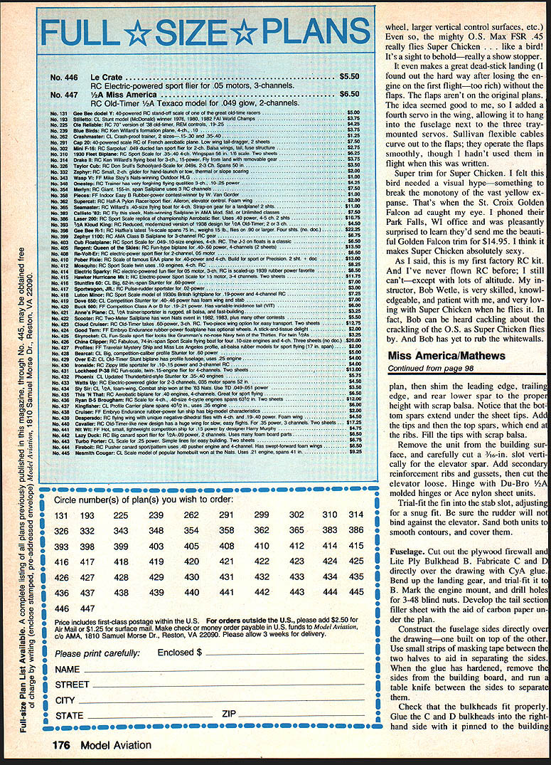
Cut two pieces of Sig Kromekote or other enameled paper to the pattern, and install them with an aliphatic resin. We found this method to be both light and realistic—with much better strength than 1/32 balsa. Complete the fuselage by installing the previously bent landing gear and the nose blocks.
The longerons aft of the cabin should be sanded to a half-round shape. We recommend a trial installation of the radio and pushrods before covering the fuselage. Pin the previously constructed tail surfaces onto the fuselage, install the engine, and then position the radio gear to obtain a slightly nose-heavy balance point. This will compensate for the added weight of the covering. The prototype balanced perfectly with the 225 mAh battery directly behind the firewall, the receiver directly behind the first bulkhead, and the servos directly behind the receiver.
Remove the hardware, and cover the fuselage. We found MonoKote adheres well to the Kromekote paper if excessive pressure is avoided. Sig's Skybrite was used for trim, sprayed directly onto the MonoKote using electrician's vinyl tape for masking. Numbers are sticky-backed vinyl from the stationery store, and the flags are sticky vinyl units found in the Sig catalog.
The engine compartment should be fuel-proofed with Skybrite clear or urethane. The Trexler wheels are also from the Sig catalog.
We prefer to test-fly in the workshop! We check for and correct any warps and misalignments, test the engine, adjust the center of gravity (CG), and range-check the radio unit at home. The reduced stress of leisurely looking over the model in the shop often prevents a disaster at the field. If everything functions perfectly, then head for the flying field.
Flying
This model is exceptionally light and quick under power. Hand launches are simple; the darn thing will fly right out of your hand with no push whatsoever! One must be absolutely sure the CG is not rearward of the point shown and the surface deflections are no more than specified. Otherwise, the 1/2A Miss America can be a nasty lady!
Properly set up, it will climb very rapidly and with a good groove. Just point the nose into the wind, and watch it go. The radio is used merely to correct the climb; no up-elevator is needed nor should it be used! Since turning the full tank will put this model so very high, we suggest filling the tank halfway for the first few flights. Frankly, if the 1/2A Miss America is intended for sport flying rather than competition, a Golden Bee would sure be nice. However, if competition is the name of the game, very few 1/4A Texaco models will outclimb this Miss!
The glide is rather gentle, requiring much larger stick movements. Miss America will thermal happily in even light lift with a wide or narrow circle. Try running at right angles to the wind—that is, left and right turns. Somewhere along the "wind wall," lift will be encountered. As soon as the model tends to turn on its own and begins to rise, set up a wide circle until the cone of lift is determined.
The relatively small size of 1/2A Texaco models makes visibility a potential problem. Don't allow the model to drift too far downwind! The 1/2A Miss America is so buoyant that it doesn't penetrate too well. If locked into a large chunk of lift, try running it left-to-right in an effort to locate the down side of the thermal. If all fails, full down elevator and full rudder will break the model out of the thermal.
Landing such a lightweight model is just a matter of lining it up and S-turning to bleed off altitude. The model floats in ground effect for a long way, which may require some down-elevator to get the wheels on the ground.
Whether the 1/2A Miss America is built for sport or competition, it will reward the builder with many hours of flying with minimal cost. Although we will not duplicate Scientific Models' guarantee that it will fly, we will guarantee that the builder will enjoy it.
Postscript
We wrote Frank Zaic to inquire if he might be the young man shown in the ad photo. He is not, but his historical background on the development is very interesting. Let us quote from his letter:
"Scientific approached me to design a model for them. I agreed, but insisted my name not be shown anywhere. I was very wary at that time that my name not be connected in any way with commercialism. You will note I never used my name in the JASCO catalog or my connection with it.
"At that time Carl Schmaedig was working for me after school. He had finished a gas model which was later published in Model Craftsmanship as the Miss Model Craftsman. So I knew he was a good builder and had ideas. He was as interested in the gas models as I was. Miss America was a combination of his work and mine. I had enough confidence in the type that I felt it would fly as shown.
"The main thing I wanted was a cabin look and for it to be fairly easy to make and sturdy. As far as aerodynamic design was concerned . . . we had no idea just what part the rudder, dihedral, etc., played in the overall picture.
"Carl finished the model with white silkspan and clear dope. We took it to Holmes Airport via the subway. Had lots of trouble starting the Baby Cyclone. The major concern was to get the engine going. When it did get started, we let the model taxi and fly off. It did very nicely with a straightaway climb of about 30°.
"It kept right on going straightaway into the distance! We never saw the model again! Well, we had proven it would fly, but it also meant that we had to make another model for Scientific.
"All this for $50.00! They had someone do the paint job and final drawings. All this means that we never did any testing to find out how it would behave in turns, etc.
"The model was named by Scientific, not us."
There, you have it. Two prototypes were built by Carl Schmaedig. The first was at Iowa once, and the second not at all.
That the Miss Americas flew well when built from the kits and flew smoothly as both free flight and RC-assisted needs no comment from us. The fact that this design has become a true classic, even though it was by some very little flying of the prototypes, speaks volumes about the incredible designing skill of Frank Zaic!
This writer has never seen a Miss America fly badly, regardless of size. Had Frank Zaic not related this story to us, we would find it most difficult to believe.
Transcribed from original scans by AI. Minor OCR errors may remain.

