
1/2A STREAKER
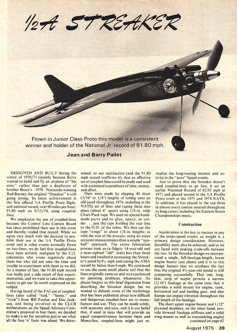
Flown in Junior Class Proto this model is a consistent winner and holder of the National Jr. record of 91.80 mph.
Jean and Barry Pailet
DESIGNED AND BUILT during the winter of 1970/71 (mainly because Barry wanted to build and fly an airplane of "his own," rather than just a duplicate of brother Bruce's 1970 Nationals-winning Red Baron), the original "Streaker" is still going strong. Its latest achievement is the first official 1/2A Profile Proto flight, and national record, over 90 miles per hour: 91.80 mph on 9/15/74, using coupled-lines.
We emphasize the use of coupled-lines because the Control Line Contest Board has since prohibited their use in this event and thereby voided that record. While we agree very much with the decision to prohibit their use in the 1/2A Profile Proto event and in other events normally flown on two-lines, we do feel that coupled-lines have been unfairly maligned by the C/L columnists who wrote negatively about them but who did not take the time and trouble to experiment with them as we did. As a matter of fact, the 91.80 mph record was really just a side result of that experimentation, and we want to take this opportunity to get our two-cents' worth expressed on the subject.
Having heard of the FAI use of coupled-lines (also called "tied," "funny," and "trick") from Bill Pardue and Doc Jackson, and being involved in the CLCB deliberations on the Speed Advisory Committee's proposal to ban them, we decided to make a set for ourselves just to see what all the fuss 'n' furor was about. We determined, to our satisfaction (and the 91.80 mph record reaffirms it), that an effective set of coupled-lines could be made and used with a minimal expenditure of time, money, and effort.
Ours were made by slipping 40 short (3/16" to 1/4") lengths of tubing onto an old (used throughout 1974, including at the NATS) set of lines and taping them into place (about 6" apart) using 1/8-in. wide Chart-Pack tape. We used no special hand-made parts and no glue, epoxy or solder — just the tape holding the rear line to the O.D. of the tubes. We then cut the tape "wings" to about 1/8-in. lengths; as with the rest of the process, using no more accurate measurements than a simple "eyeball" approach. The entire fabrication process took us (a fidgety 14-year-old "old" man) less than three hours and resulted in increasing the Streaker's speed by 9 mph and raising the AMA record by better than 6 mph. We continued to use the same small plastic reel the lines originally came on and we experienced no jamming problems whatsoever. So please forgive us this brief digression describing the Streaker design; we wanted to debunk some of the mythology that has been published about how difficult and dangerous coupled-lines are to manufacture and use. They can be made safely, with economy and ease, and if used in sizes that will provide equal competitiveness between them and mono-line, coupled-lines might just re-vitalize the long-waning interest and activity in the "pure" Speed events.
Just to prove that the Streaker doesn't need coupled-lines to go fast, it set an earlier National Record of 82.92 mph in 1971 and placed second in the 1/2A Profile Proto event at the 1971 and 1974 NATS. In addition, it has placed in the top three in almost every contest entered throughout its long career, including the Eastern States Championships meets.
Construction
Acceleration is the key to success in any of the proto-speed events, so weight is a primary design consideration. However, durability must also be achieved, and so we are faced with making trade-offs between the two. In the Streaker design we incorporated a single, full-fuselage-length, lower engine bearer (see plans) and it is to this design feature that we attribute the fact that the original 4-year-old model is still competing successfully. That one, long, thin strip of maple permits a narrow 3/16" fuselage at the same time that it provides a solid mount for engine, tank, horizontal tail and landing gear, and also dampens out engine vibration throughout the full length of the fuselage.
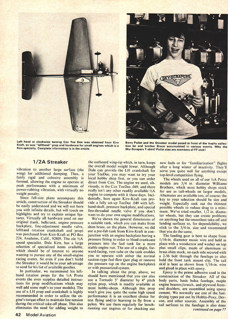
The short upper engine bearer and 1/32" plywood doublers, on the other hand, provide forward-fuselage stiffness and a solid forward-fuselage mounting as well as transmitting engine the outboard wing-tip which, in turn, keeps the overall model weight lower. Although Dale can provide the LH crankshaft for your TeeDee, you may want to try your local hobby shop first, or you can order direct from Cox. The engine we used, obviously, is the Cox TeeDee .049, and there really isn't any other readily available 1/2A engine to compete with it these days. Incidentally, here again Kirn-Kraft can provide a fully set-up TeeDee .049 with left-hand shaft, pressure backplate, and special fine-threaded needle valve if you don't want to do your own engine modifications.
We've shown the general dimensions of a suitable tank, which you can make from shim brass, on the plans. However, we did use a pre-fab tank from Kirn-Kraft in conjunction with an engine backplate having a pressure fitting in order to bleed crankcase pressure into the fuel tank for a more stable engine run. The use of a single, forward-facing, vent tube on the tank enables you to operate with either the normal suction-type fuel flow (just plug or remove the pressure tap on the engine backplate) or with a pressurized system.
In talking about the prop, above, we should have mentioned that you can also use a Tornado 5" diameter by 4" pitch nylon prop, which is readily available at most hobby-shops. Although this prop won't give you quite the same high speed performance as the 4" balsa prop for contest flying and/or learning to fly from a pylon, we use them regularly for bench-running our engines or for checking out new fuels or for "familiarization" flights after a long winter of inactivity. They'll serve you quite well for anything except top-level competition flying.
The wheels used on all of our 1/2A Proto models are 3/4 in. diameter Williams Brothers wheels, which most hobby shops stock for use as tail-wheels on larger models. Alternates are available too, of course; the thing to worry about is wheel size and weight. Especially seek out the thinnest possible wheels to reduce drag to a minimum. We're told smaller, 1/2 in. diameter wheels are available, but they can create problems on anything but the smoothest take-off and landing surfaces so, for dependability, we stick to the 3/4-in. size and recommend that you do the same.
The landing gear is bent to shape from 1/16-in. diameter music wire and is secured to the fuselage with a 1/32-in. wide brass shim clamp and held in place by small screws as shown on the plans. A 1/8-in. diameter hardwood dowel, slotted to accept a 2-56 bolt through the lower end, is used to retain the gear. The tail skid is 1/16-in. music wire and is glued in place with epoxy.
Epoxy is the prime adhesive used in the construction of the Streaker. All of the body parts — basic balsa fuselage, maple engine bearers/crutch, tail and plywood formers and doublers — are assembled using epoxy. We normally use one of the fast-drying types put out by Hobby-Poxy, Devcon, and other sources. with epoxy, as is the installation of the elevator hinges.
The horizontal stabilizer and elevator are carved and sanded to shape before the elevator is cut away from the full tail piece. After cutting the planform from 3/32-in. hard sheet balsa it should be shaped to the approximate airfoil contour shown; this shape is not critical but it must be symmetrical. The elevator is then cut away from the stabilizer and the hinges installed. The hinges are simply short lengths of 1/16-in. O.D. aluminum tubing slipped over a length of 1/32-in. music wire and epoxied alternately to the stab and elevator. The small elevator horn can be made from aluminum stock and bolted in place or from a small piece of 1/32- or 1/16-in. plywood and glued to the elevator with epoxy, or you can purchase one similar to that shown at your hobby shop and install it in whatever manner is called for.
The vertical tail, or fin, is cut from 1/32-in. sheet plywood, the leading and trailing edges sanded to a slight taper and rounded, and installed with epoxy. It is made from plywood to better withstand the rigors of an occasional flip-over on landing, which is bound to occur sooner or later, especially on a not-perfectly-smooth landing site. The clear plastic canopy, which is required by the AMA rules for this event, is epoxied in place at the intersection of the fin leading edge and the top of the fuselage. The actual shape is not really critical so it can be made by either modifying one of the many small "bubble-type" canopies sold in most hobbyshops or purchased from Kirn-Kraft.
Carving the wing of the Streaker is probably the most difficult task in building the model, but can be performed most easily by following the steps described. Cut the planform shape from a plank of 3/16-in. thick balsa. From the plans locate the proper position for the small maple bellcrank mount and glue it into the wing blank with epoxy. While the wing blank is still flat-sided it would be advisable to drill the bellcrank mounting hole through the maple insert.
Begin carving the wing by tapering its thickness from the maximum 3/16-in. at the root to 1/16-in. at the tip; the taper should be on the lower surface so that the upper surface remains completely flat from tip to tip (this gives a very slight dihedral appearance). The next step is best performed with a fine-tipped magic marker, but a soft pencil can be used as an alternate. Draw a straight line, normal to the model's and wing's centerline and running through the bellcrank center from tip to tip on both the top and bottom surfaces of the wing blank. These lines locate the maximum thickness location of the airfoil, for reference during the carving process. Additional lines should be drawn along the leading and trailing edge faces of the wing blank running from the mid-point of the tip thickness to a point 1/16-in. above the lower surface at the root, to denote the actual airfoil leading and trailing edges as the flat blank is carved to shape.
Using the line-guides just drawn on the edges and surfaces of the wing blank the basic airfoil shape now can be carved. We find a razor plane the best tool for this purpose, and we do the rest of the job with no further recourse to special contours or templates; the four basic guidelines will result in a lifting section at the root gradually changing to a symmetrical one at the tip and the specific airfoil contour, in our opinion, simply is not all that critical. Final shaping of the wing is done with fairly rough sandpaper (we use #220 grit), prior to fine sanding and finishing.
Fuselage construction was described in general earlier, and is comparable to any normal "profile" model. Our normal sequence is to rough-out the side-view shape on the 3/16-in. hard balsa plank, install the maple engine-bearers with epoxy, and then glue on (with epoxy) the 1/32-in. plywood doublers. After this assembly has dried, drill the necessary mounting holes for the engine, landing gear, and tank, and cut the airfoil-shaped openings required for wing and tail installations. The upper and lower fuselage edges should be rounded with sandpaper. Prior to final assembly of the wing/tail/fuselage we recommend that they each be given one coat of hot-fuel-proof (butyrate) dope in order to partially seal the wood grain and afford a better glue joint. Lightly sand the parts with a medium grit (about #320) sandpaper and assemble them using epoxy glue, being especially careful to get proper alignment relative to each other. The wing-tip line guide can also be installed at this time, and it should either be made from 1/32-in. plywood and glued to the wing, or from aluminum shim stock and bolted in place.
The entire model should be given a minimum of three coats of clear butyrate dope (or your favorite hot-fuel proof sealer/undercoat compound) with sanding in between using a fine grit (about #400) sandpaper. Choice of color scheme is up to you; the original model is all-purple (with a name like Streaker, maybe flesh color would have been more appropriate?). For simplicity and ease of touching-up those nicks which will inevitably result from competition flying we do recommend, however, that you stick to one basic color and do not get too elaborate. Another good idea is to give the entire model an over-coat of clear Hobbypoxy. This should be done after the last coat of dope has dried for at least a day, and will provide better protection from the "hotter" speed fuels.
Installation of the landing gear, as described earlier, and the control system will complete your model's construction. Although any small, #4 A sized, bellcrank will suffice, our preference is for a special one available from Kirn-Kraft. It is special because it incorporates the same line-connecting system used on most Mono-line devices: small brass buttons around which the line end-loops slip. This not only eliminates the need for special lead-out wires and connector clips but provides a safer attachment because of the larger area around which the line end-loop rubs. The bellcrank/1/16-in. hollow aluminum bushrod is made from 1/16-in. music wire, bent to the appropriate length to give neutral elevator when the bellcrank is in the neutral position.
Our basic engines are unmodified except for a few small refinements such as removing any sharp edges from the inside of the crankcases and opening the venturi throat to a diameter somewhere between .136" and .150" (the best size for a given engine and set of flying conditions can only be determined by test flying). The regular high-compression heads that Cox now provides for the TD's are quite competitive, but if you have access to a small lathe you can experiment with modifying them to further increase the compression ratio. We generally cut about .015" off the Cox head and then experiment by flight testing with anywhere from one to three gaskets under the head until we get the best results. Here again, expect the results to vary with different fuels and climates. Another area of experimentation which can yield significant results is to try many different piston/cylinder combinations.
For initial flight tests we recommend you use the Cox Red Can fuel and Tornado prop, and adjust the controls for minimum sensitivity by keeping the lines close together (about 1" at the handle). Learning to "fly in the pylon" should offer no difficulty, but if you encounter problems getting your wrist into the fork on the pylon after take-off we urge you to use Barry's method (used by many other youngsters, as well) of simply beginning the take-off and flight with your wrist already in the fork. After a few familiarization flights try one of the Kirn-Kraft props and some "hotter" fuel.
Competition fuels are very much a function of the weather and the idiosyncrasies of your particular engine. Readily available hot fuels such as Ramin and K & B Speed Fuel are certainly worth a try. For home-brews we depend heavily upon the trap mixtures concocted by Frank Garzon, but we can offer one tip ... we never use less than 60 percent nitro in the mix.
If your model weighs five ounces or less, and you fly on the AMA regulations lines of .008" diameter by 42' long, competitive speeds will be right around 80 mph. Anything under 75 mph calls for continued work on the engine/prop/fuel combinations. If you get into the 80+ mph bracket, we'll meet you in Lake Charles, Louisiana at the 1975 Nationals this summer and see if your Streaker can beat Barry's original, ole-reliable, Streaker.
Transcribed from original scans by AI. Minor OCR errors may remain.

