
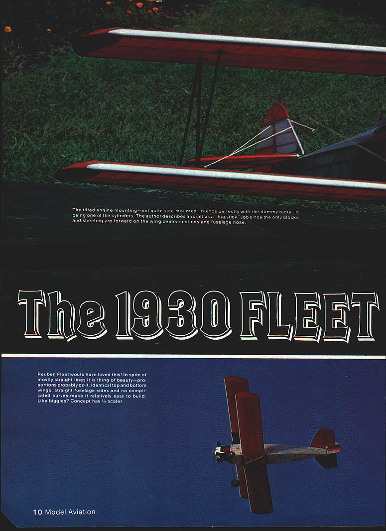
The 1930 Fleet
The tilted engine mounting — not quite side‑mounted — blends perfectly with the dummy radial, appearing as one of the cylinders. The construction is essentially a "big‑stick" job since the only sheeting is forward on the wing center sections and the fuselage nose. Reuben Fleet would have loved this design. In spite of mostly straight lines it is a thing of beauty; the proportions are probably the key. Identical top and bottom wings, straight fuselage sides and no complicated curves make it relatively easy to build. — Gary E. Brown
Design and scale
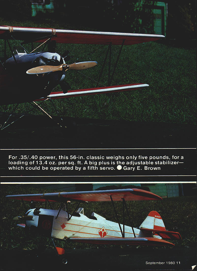
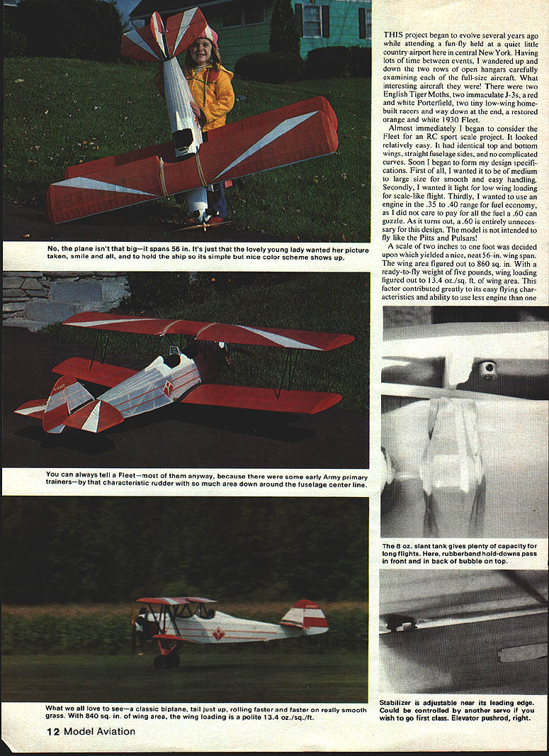
A scale of two inches to one foot was chosen, which yields a neat 56‑in. wingspan. The wing area figures out to about 860 sq. in. With a ready‑to‑fly weight of five pounds, wing loading is approximately 13.4 oz./sq. ft. These factors contribute to easy, scale‑like flight and allow the use of a .35–.40 engine for good fuel economy (a .60 is unnecessary).
The stabilizer is designed with adjustable incidence and can be adjusted near its leading edge. It could be operated by a fifth servo if you wish. The elevator pushrod is on the right.
Performance
- Takeoffs are short and graceful; the airfoil and slant tank lift the tail quickly.
- The model can be flown very slowly in a scale‑like manner without fear of stalling.
- As a light biplane with lots of drag, it will slow down quickly. A light idle can cause it to stretch the glide; a higher idle can make it float on landing.
- Ailerons become less effective at very low speed, but rudder control remains good and the model does not tend to drop a wing tip.
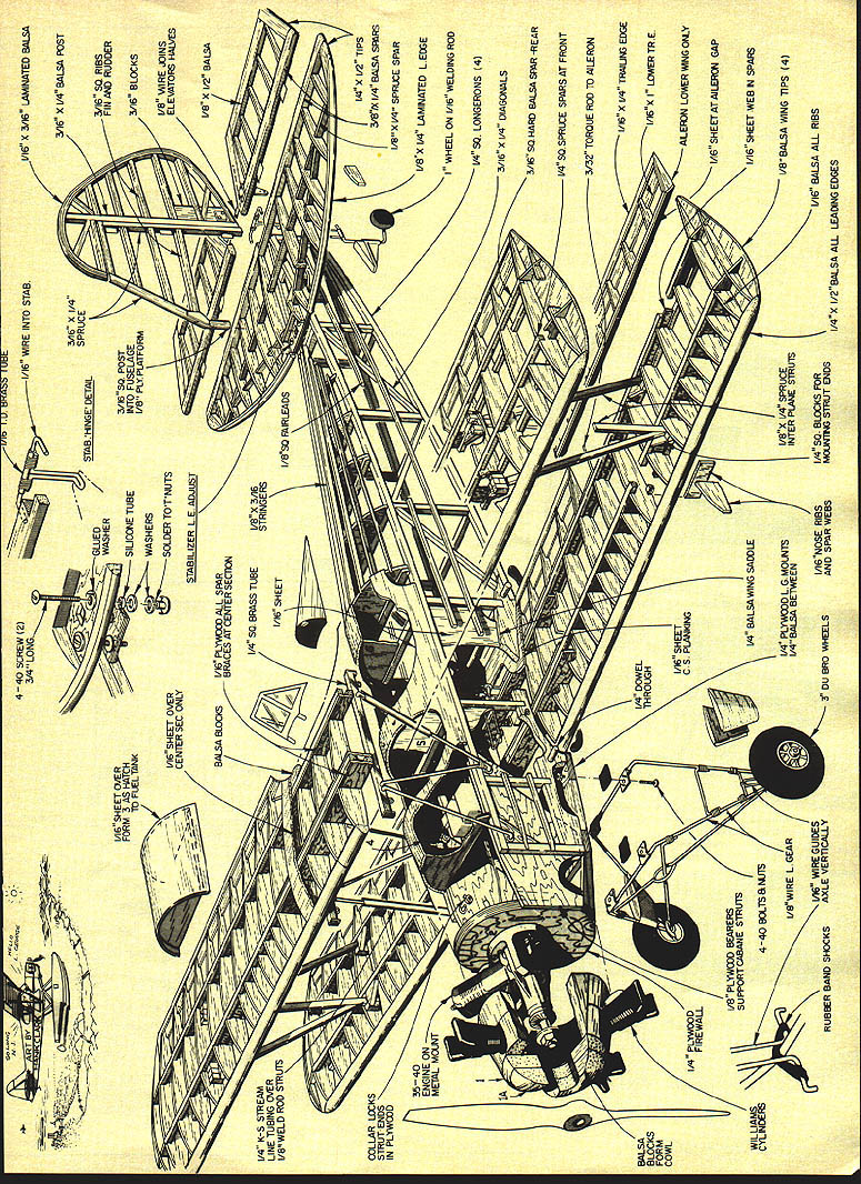
Construction overview
Construction is primarily a big‑stick approach: sheet the solid surfaces forward on the fuselage and wing center sections, and build the other components up for lightness and strength. Both wings are built over the same plan and are identical except for the lower‑wing ailerons and their center sections. The stabilizer has adjustable incidence.
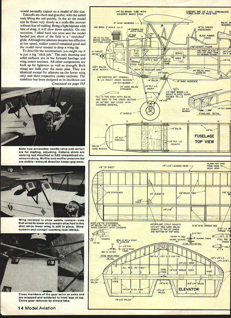
Fuselage
- Carefully align and join the left and right fuselage sides with 1/4" cross members to form the basic box structure.
- Roughen all plywood joints to be epoxied or cemented with coarse sandpaper.
- Add the firewall, formers, stringers, and both exterior and interior sheeting to complete the fuselage.
- Note: the cabane mounting holes in the 1/4" plywood gussets are lined with 1/8" I.D. brass tubing.
- Temporarily bolt the mount and engine to the firewall, fit the nose blocks, and shape them to match the engine and exterior dimensions.
- A 1/16" sheet is used over the formers as a hatch to the fuel tank. Use 1/16" sheet over the center section only. Rubber‑band hold‑downs pass front and back.
Tail section
- Construct the tail components over the plans. Select soft balsa strips for the laminated rudder trailing edge and stabilizer leading edge.
- Soak the strips in hot water and bend them around a cardboard form of the rudder and stabilizer; tape into position until dry, then glue them to the structure.
- Strengthen the leading edge of the fin at the joint just above the stabilizer.
- Construct the stabilizer trim adjustment parts and check operation while temporarily mounted with the other tail components.
- After covering the stabilizer, epoxy the rear hinge in place and permanently affix the two 4‑40 bolts by soldering washers against the silicone tubing over the bolts (this holds the stabilizer up against the bolt heads).
- Also solder washers to the top of the blind nuts to keep them from dropping into the fuselage.
Cabanes, interplanes, landing gear
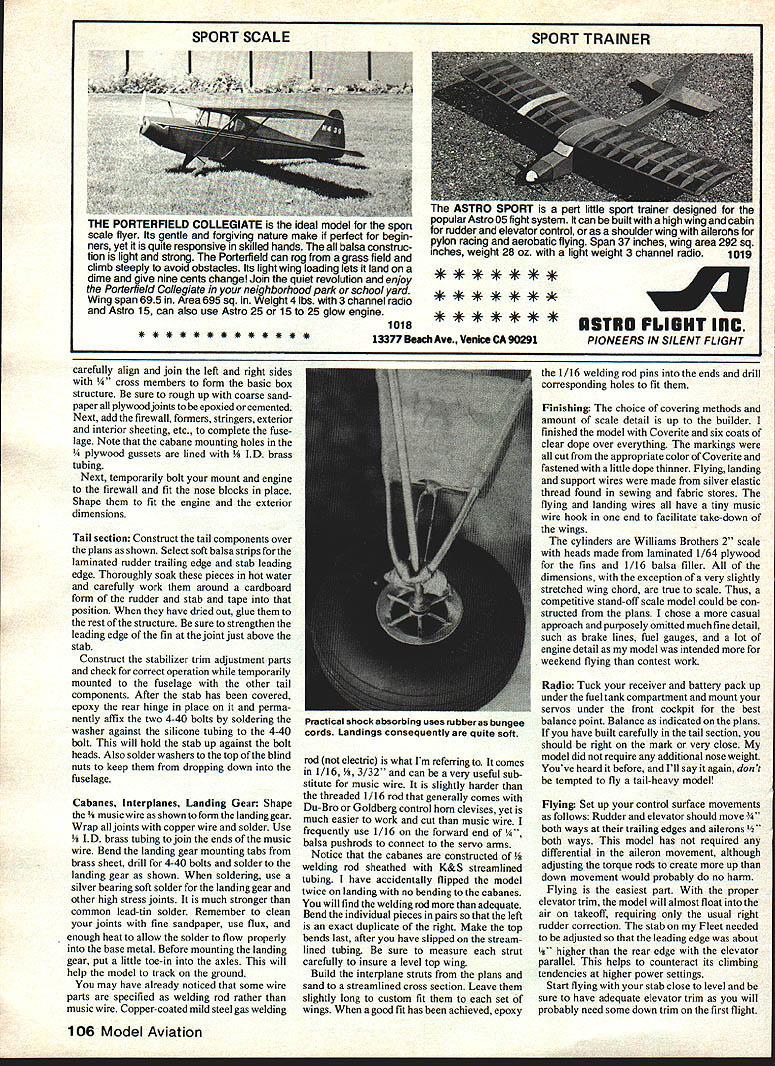
- Shape the "V" music wire as shown on the plans to form the landing gear. Wrap all joints with copper wire and solder.
- Use 1/8" I.D. brass tubing to join the ends of the music wire.
- Bend landing gear mounting tabs from brass sheet, drill for 4‑40 bolts, and solder to the landing gear. Use a silver‑bearing soft solder for landing gear and other high‑stress joints — it is stronger than common lead‑tin solder.
- Clean joints with fine sandpaper, use flux, and apply enough heat for the solder to flow properly.
- Before mounting the landing gear, add a little toe‑in to the axles to help the model track on the ground.
- The cabanes are constructed of welded rod sheathed with K & S streamlined tubing. Bend the individual pieces in pairs so left and right are duplicates; make the top bends last after slipping on the tubing. Ream each strut carefully to ensure a level top wing.
- Build the interplane struts from the plans and sand to a streamlined cross section. Leave slightly long to custom fit to each wing set. Epoxy 1/16" welding rod pins into the ends and drill corresponding holes to fit them.
Materials and tips
- Some wire parts are specified as copper‑coated mild steel gas welding rod (not electric), available in 1/16" and 3/32". It is slightly harder than the threaded 1/16" rod and easier to work and cut than music wire.
- I often use 1/16" welding rod on the forward end of 3/32" ball bearing rods to connect servo arms.
- When soldering, clean, flux, and use sufficient heat. Use silver‑bearing soft solder for high‑stress joints.
Finishing
- Choice of covering method and amount of scale detail is up to the builder. The example model was finished with Coverite and six coats of clear dope.
- Markings were cut from colored Coverite and attached with a little dope thinner.
- Flying, landing and support wires were made from silver elastic thread from fabric stores. Flying and landing wires have tiny music‑wire hooks on one end for wing take‑down.
- The cylinders are Williams Brothers 2" scale units with heads made from laminated 1/64" plywood fins and 1/16" balsa filler.
- Except for a very slightly stretched wing chord, the dimensions are true to scale; a competitive stand‑off scale model could be constructed from the plans. The author omitted some fine detail (brake lines, fuel gauges, extensive engine detail) to keep the model more for weekend flying than contest work.
Radio and equipment layout
- Tuck the receiver and battery pack under the fuel tank compartment and mount servos under the front cockpit for the best balance.
- Balance as indicated on the plans. If the tail section was built carefully, little or no nose weight should be required.
- Do not fly a tail‑heavy model.
Flying
- Control surface movements:
- Rudder and elevator: about 3/4" each way.
- Ailerons (trailing edges): about 1/2" each way.
- The model has not required aileron differential, though a slight bias (more up than down) would not harm.
- With proper elevator trim the model will almost float into the air on takeoff, requiring only a little up‑elevator correction.
- Set stabilizer incidence so the leading edge is about 1/8" higher than the rear edge with the elevator parallel; this helps counteract climbing tendencies. Start flights with the stabilizer close to level and be ready to add down trim on early flights.
- When landing, don't cut the throttle too soon; the model slows quickly. If the idle is too high it can float past the landing point. Begin to pull the tail down in a flare just before touchdown to take advantage of the airfoil's stability.
- Overall, the Fleet flies like a trainer: big, lazy maneuvers and relaxed flying are appropriate.
Specifications
- Scale: 2" = 1'
- Wingspan: 56"
- Length: 42"
- Wing area: 860 sq. in.
- Weight: 5 lbs.
- Engine: .35 to .40
- Radio: Four‑channel — rudder, elevator, motor, and ailerons.
Transcribed from original scans by AI. Minor OCR errors may remain.

