
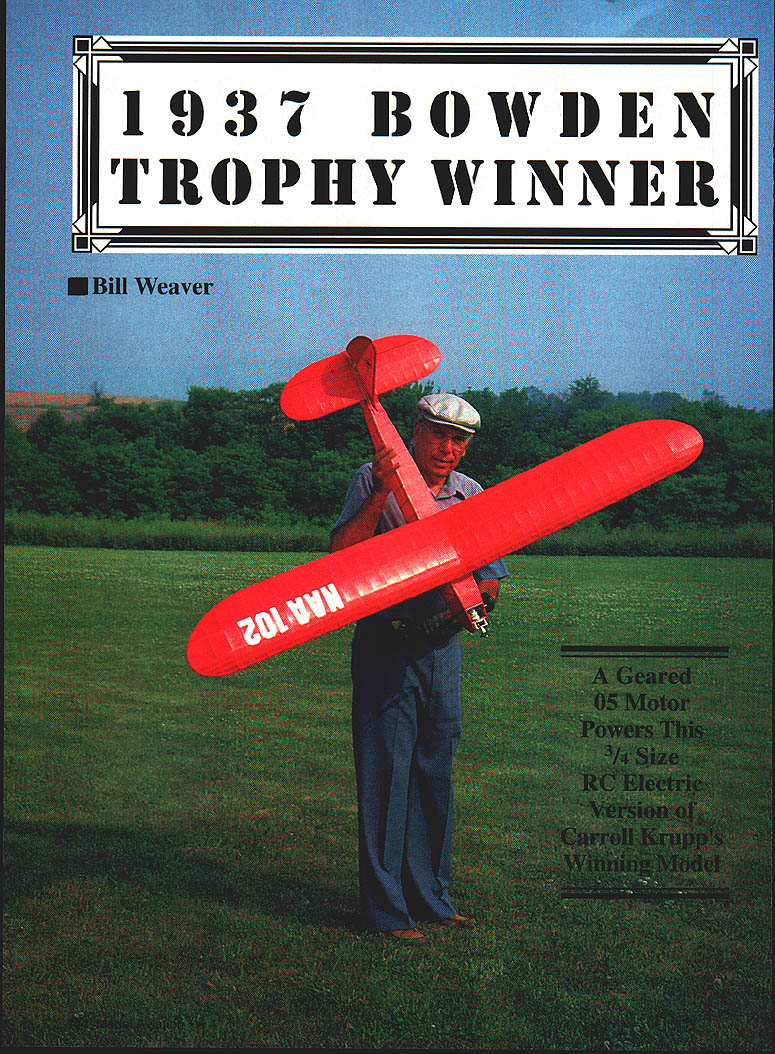
1937 Bowden Trophy Winner
Bill Weaver
The 1937 Wakefield International contest for free-flight rubber-powered models was held in England on Sunday, August 1, 1937. The event was won by Emanuel Fillon of France. The American Wakefield team of Alvie Dague, Dick Bodle, Herb Fish, Frank Zaic, and Henry Struck did not come home empty-handed: the Bowden International Trophy contest for gas-powered models was won the next day by Herb Fish, flying a model designed and built by Carroll Krupp of Akron, Ohio.
The Bowden event was not a timed-duration type but was judged by a complex set of rules involving appearance, a timed flight of 45–90 seconds, controllability and stability, and the ability to take off and land undamaged. At the end of the scheduled flying, four fliers, including Herb Fish, were tied for first place. After another round two fell short, leaving Herb Fish and an Englishman. In the next round the English plane landed a little hard and bent its landing gear, so the American plane won.
Plans for Krupp's winning model were included in Frank Zaic's 1938 Yearbook. The plan was reproduced, with commentary, in Dr. D. B. Mathews' Old-Timers column in the June 1986 Model Aviation. That article revived my interest in the design.
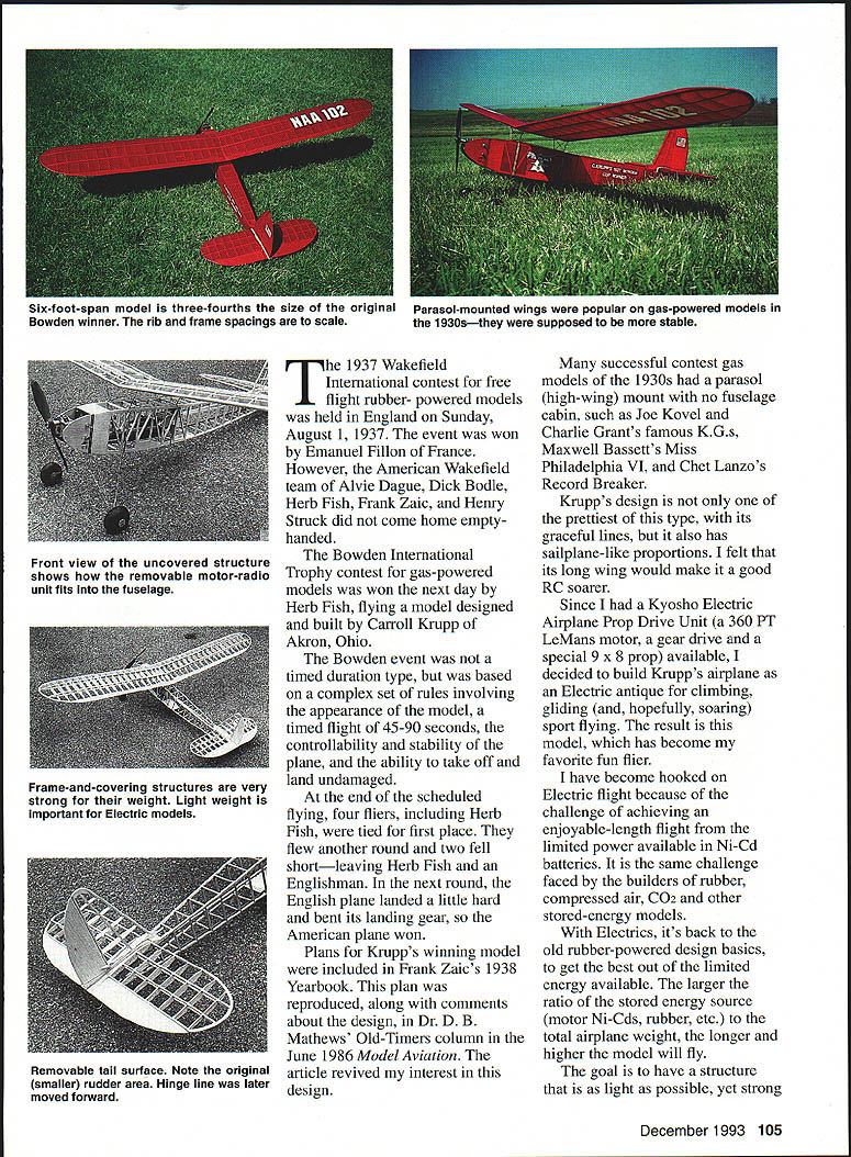
Many successful contest gas models of the 1930s had a parasol (high-wing) mount with no fuselage cabin—examples include Joe Kovel and Charlie Grant's K.G.s, Maxwell Bassett's Miss Philadelphia VI, and Chet Lanzo's Record Breaker. Krupp's design is among the prettiest of this type, with graceful, sailplane-like proportions and a long wing I felt would make a good RC soarer.
Having a Kyosho Electric Airplane Prop Drive Unit (a 360 PT LeMans motor, gear drive and a special 9x8 prop) available, I decided to build Krupp's airplane as an electric antique for climb-and-glide sport flying and hoping to soar. The result is a six-foot-span, 3/4-size model that has become my favorite fun flier.
I became hooked on electric flight because of the challenge of achieving enjoyable-length flights from the limited power available in Ni-Cd batteries—the same challenge faced by builders of rubber, compressed air, CO2 and other stored-energy models. With electrics you return to rubber-powered design basics: maximize the ratio of stored energy to total airplane weight. The goal is a structure as light as possible yet strong.
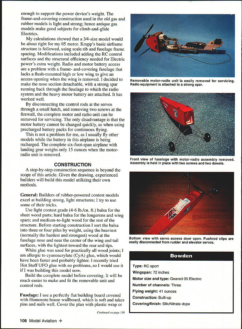
My calculations showed a 3/4-size model would suit my .05 motor. Krupp's basic airframe structure was followed, using scale rib and fuselage frame spacing, with modifications to add RC control surfaces and the structural efficiency needed for electric power's extra weight. Radio and motor battery access is a problem with a frame-and-covering fuselage that lacks a flush-mounted high or low wing opening; I made the nose section detachable, with a strong spar running back through the fuselage to which the radio system and heavy motor battery are attached. By disconnecting the control rods at the servos through a small hatch and removing two screws at the firewall, the complete motor-and-radio unit can be removed for servicing. The only disadvantage is that the motor battery cannot be changed quickly; I typically fly other models while this airplane's battery is recharging. The complete six-foot-span airplane with landing gear weighs only 15 ounces when the motor-radio unit is removed.
CONSTRUCTION
A step-by-step construction sequence is beyond the scope of this article. Given the drawing, experienced builders will build this model using their own methods. The following notes and techniques describe how I built mine.
General
- Builders of rubber-powered contest models excel at building strong, light structures—use some of their tricks.
- Use light contest-grade (4–6 lb/ft³) balsa for sheet parts; hard balsa for longerons and wing spars; medium-to-light wood for the rest.
- Before starting, sort balsa into three or four piles by weight. Use the heaviest (normally hardest and strongest) wood at the fuselage nose and near the center of wing and tail surfaces, with the lightest toward the rear and tips.
- White glue was used for nearly all wood joints. I am allergic to cyanoacrylate; Hot Stuff UFO glue has worked well for me and is an acceptable substitute.
- Build the complete model before covering; it makes fitting the removable unit and control rods much easier.
Fuselage
- Use a perfectly flat building board covered with Homosote house wallboard. Cover the plan with plastic wrap or waxed paper.
- Hold longerons in place with 1-inch-long 16-gauge brads. Soak the front half of the longerons and the 1/8 x 3/16 longeron doublers at the nose in hot water and dry them in the brad jig before adding uprights to avoid springing the sides out of shape.
- I make the first fuselage side and, while the brads remain, make two of each upright. After removing the glued first side, replace the brads and glue in the already-made uprights for the second side; identical longerons ensure a snug, identical fit.
- A protractor-guided hand sanding block is helpful to size uprights and diagonals for neat fits.
- The lower opening in FU-2 is for motor-battery cooling air; it exits through the louvered servo door. I covered this opening with window screen to keep debris out. The upper opening directs cooling air to the speed-control cooling fins.
- Note the lower longerons are cut away to clear the hardwood landing-gear attachment blocks.
- I used a bamboo tail skid formed over a 3/4-inch dowel with a heat gun. Bend with the shiny side outward.
- The small door just in front of the stabilizer allows the rudder control rod to be removed. It is cut free on two sides after covering so the covering acts as a hinge. The servo access door uses the covering as its hinge as well.
- The thrustline shown is the scale centerline of the original Brown Jr. engine and is not raised by any gearbox offset.
Wing
- The wing structure differs from the original except for scale rib spacing. Bob Kopksi's tapered-spar system was used for strength and lightness (see "All About Electrics, Part 8," April 1984 Model Aviation).
- Two 1x-square turbulator spars were used instead of a sheet-covered leading spar. Laminated tips are soaked in hot water and pulled around a form at least 1/4 inch thick; use a few extra inches to tack the ends. When dry, paint with white glue and reattach to the form to set shape. I used a scrap of 3/8 plywood bandsawed to contour for my forms.
- Trace sheet parts on tracing paper and stick them to balsa sheet or templates with rubber cement. After cutting, peel the tracing off; any leftover cement rubs off.
- If a thin plywood or aluminum template is made for rib W-2, a full set of identical ribs can be cut. Drive a brad through the template near the leading and trailing edges while backing up with wood; the toothed perforation prevents slipping.
- The spars and turbulator strips are not forcibly cracked; allow them to naturally bend down or up to the tips. Dampen the top spars at the last W-2 rib to assist bending.
- Make the wire wing mount parts as accurately as possible. The 1/32-inch bracing is tack-soldered to the front and rear struts. Bind joints with fine wire (I used lamp-cord strands). The mount will be floppy at first but will tighten as parts are added; some wrappings will need rewinding to accommodate added parts.
- When the mount holds together, set it on a piece of wood to simulate the fuselage and pin or tape the front and rear struts to hold alignment. Shape the wing-rubber attach hooks so the wing can cam off and release rubber bands if a tip hits in a crash. Slide the hooks snugly to the three-inch-wide piece; they align the wing to the fuselage—avoid slop here.
- If everything is square, solder using high-strength silver solder (4% silver, 96% tin—Kester or Stay-Brite). After soldering, attach a three-inch-wide piece of fine emery cloth to the wood and rub the mount until wrapping wire or solder bumps are smoothed off, leaving four small smooth flats that will sit without rocking on the fuselage gear plates.
- Attach the mount to the wing at the leading and trailing edges so the wing incidence is 4°. Bend the top ends of the struts parallel with wing parts if necessary. Check that the wing is 90° to the fuselage before final gluing. Add 1/16-inch sheet around the wire exits for glue area and 1/8-inch caps at the wing centerline for the same purpose.
- The covered wing, including the wing mount, weighed 7-1/4 ounces on my model.
Tail Surfaces
- The stabilizer and fin use the same construction methods as the wing. Elevator and rudder are very light contest-grade balsa sheet to eliminate warps and simplify construction. Diagonals were added to the fin when covering bowed the hinge line.
- Robart Mini Hinge Points are light, easy to install, and allow frictionless movement. Do not glue them in until after covering.
- The hidden elevator horn is a bit complicated but manageable.
Motor and RC Unit
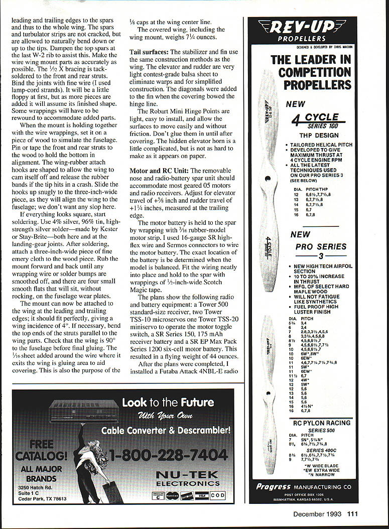
- The removable nose and radio-battery-spar unit should accommodate most geared .05 motors and radio receivers. Adjust for elevator travel of ±5/8 inch and rudder travel of +1-1/4 inches, measured at the trailing edge.
- The motor battery is held to the spar with 3/16-inch rubber-motor strip. I used 16-gauge SR high-flex wire and Sermos connectors for motor wiring. The exact battery location is determined when balancing. Fit wiring neatly and hold to the spar with wrappings of 1/2-inch-wide Scotch Magic tape.
- The plans originally showed this radio and battery equipment:
- Tower 500 standard-size receiver
- Two Tower TSS-10 microswitches
- One Tower TSS-20 miniservo for the motor toggle switch
- SIR Series 150, 175 mAh receiver battery
- SR EP Max Pack Series 1200 six-cell motor battery
- That configuration yielded a flying weight of 44 ounces. I later installed a Futaba Attack 4NBL-E radio, a combination receiver-speed control and two miniservos. Because this receiver runs from the motor battery, it eliminated the separate receiver battery and the servo-operated motor shutoff toggle and servo—saving about three ounces and improving performance. The receiver-speed-control combo is mounted in the cooling-air duct as shown in the fuselage side view. Two Futaba aileron extensions can be used to connect the receiver to the servos.
Covering
- For an antique effect I covered my model with red heavyweight silk and three coats of clear nitrate dope. It requires about two square yards of material.
- I use Coverite Balsarite to attach silk and tissue. Balsarite is a hot-melt, quick-drying liquid brushed onto the framework where covering is to be adhered. Using a model-sealing iron you can tack the covering around the edges, soften the tacks, and re-stick to remove slack or wrinkles. When smooth, permanently iron down edges.
- The wing covering is slit to fit around the wing-mount wires, then sprayed with water to shrink tight and doped. Balsarite will hold; it does not loosen.
- Micafilm is the best substitute for silk—tough, nearly as light, translucent like doped silk or tissue, and available in many colors.
Final Assembly
- Attach the 1/32-inch plywood wing mount wear pads and stabilizer trailing-edge reinforcements after covering.
- When attaching the lower stabilizer reinforcements, line up the rudder-stabilizer assembly with the airplane centerline and place them snugly against the fuselage; they act as alignment keys when removing or attaching the tail assembly.
- Adjust the battery on the spar to make the model balance at the point shown on the plans.
- To install the motor-radio unit: tape the servo and motor door open. With the fuselage vertical, drop the radio antenna in until its end reaches the door. Tilt the fuselage so the antenna end comes out the door, lower the unit and engage the spar end in the FU-4 support. Engage the nose firewall in the two 1/8 locating dowels and slip the nose into place; install the two 4-40 screws.
- Stuff the antenna into its tube, attach the two control rod links to the servos, and close the door. I use a six-inch piece of .047 music wire with a 3/8-inch 90° bend as a tool to open the links while supporting the servos. For support under the links when closing, use a six-inch length of 1/4-inch brass tubing with a 3/8-inch length flattened and bent to 90°. The wing is held on with three #33 rubber bands at the wing struts (front and rear) and the stabilizer with three #32 rubber bands.
FLYING
- This model is not a clean sailplane; drag from landing gear, wing struts and a large frontal area necessitates additional power to achieve a reasonable climb. Use one of the hotter .05 motors.
- My LeMans 360PT motor draws 23–24 amps (about 140 watts) during the useful run of about 3-1/2 minutes. This allows two climbs to well above usual sailplane winch-launch height. In still air it averages eight- to nine-minute flights. It has a good glide and will soar well in lift.
- High-wing parasol models tend to be slow responding to rudder control going into and out of turns. During test flights I found more rudder area was needed; the rudder hinge line was moved forward on the plans to increase area. The model is now easily kept under control and is very stable longitudinally. After five summers of flying I am using the wing incidence and balance point shown on the plans.
- The model's strength was tested during early flights. I experienced radio glitching and motor cutouts in the air despite perfect ground checks. After a full-rudder spiral resulting in a nose-and-tip impact the wing separated as designed; damage was limited to one wingtip, bent landing gear and prop shaft, and a few small dents in the nose cowl. The motor battery had shifted forward 3/8 inch despite being tightly rubber-banded.
- Replacing the speed control with a servo-operated on-off motor switch eliminated the radio problems. A speed control is not necessary for climb-and-glide flight. This issue likely stemmed from a peculiarity of my radio or motor setup rather than a condemnation of speed controls in general.
Bowden / Weaver
Transcribed from original scans by AI. Minor OCR errors may remain.

