
1941 TAYLORCRAFT BC-12-65
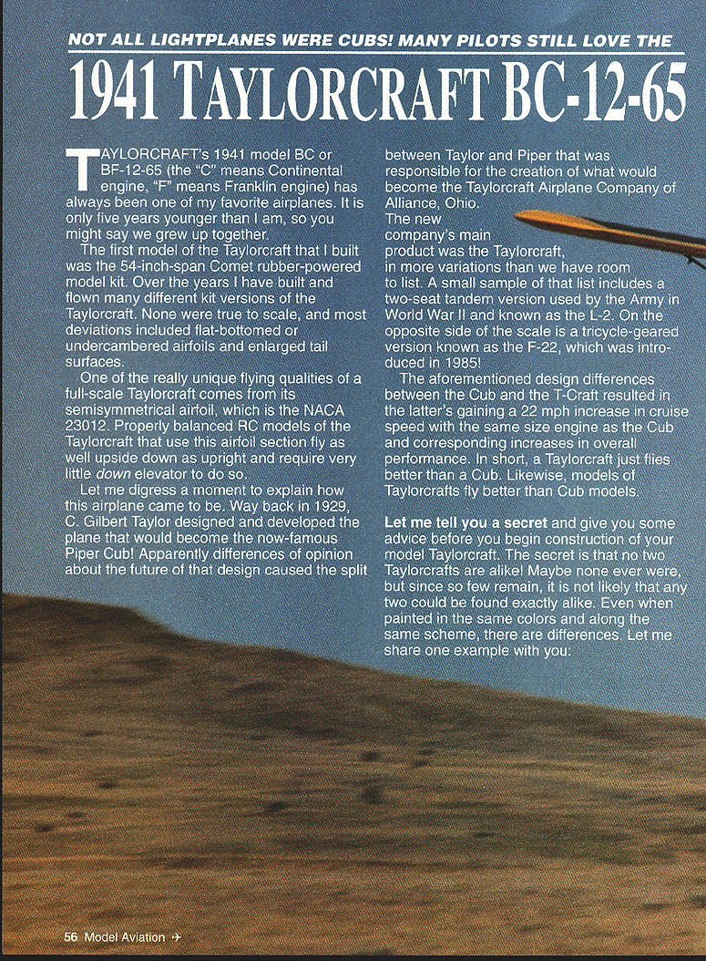
TAYLORCRAFT's 1941 model BC or BF-12-65 (the "C" means Continental engine, "F" means Franklin engine) has always been one of my favorite airplanes. It is only five years younger than I am, so you might say we grew up together.
The first model of the Taylorcraft that I built was the 54-inch-span Comet rubber-powered model kit. Over the years I have built and flown many different kit versions of the Taylorcraft. None were true to scale, and most deviations included flat-bottomed or undercambered airfoils and enlarged tail surfaces.
One of the really unique flying qualities of a full-scale Taylorcraft comes from its semisymmetrical airfoil, the NACA 23012. Properly balanced RC models of the Taylorcraft that use this airfoil section fly as well upside down as upright and require very little down elevator to do so.
A brief history: way back in 1929 C. Gilbert Taylor designed and developed the plane that would become the now-famous Piper Cub. Differences of opinion about the future of that design caused the split between Taylor and Piper and led to the creation of the Taylorcraft Airplane Company of Alliance, Ohio. The new company's main product was the Taylorcraft, in more variations than we have room to list. A small sample includes a two-seat tandem version used by the Army in World War II and known as the L-2, and a tricycle-geared version known as the F-22, introduced in 1935.
The design differences between the Cub and the T-Craft resulted in the latter gaining a 22 mph increase in cruise speed with the same-size engine as the Cub and corresponding increases in overall performance. In short, a Taylorcraft just flies better than a Cub. Likewise, models of Taylorcrafts fly better than Cub models.
A secret and some advice before you begin construction: no two Taylorcrafts are alike. Maybe none ever were, but since so few remain, it is not likely that any two could be found exactly alike. Even when painted the same, there are differences. For example: I designed a quarter-scale version of Duane Cole's famous clipped-wing T-Craft. The rudder hinge line was 11 inches (scale measurement) on the model as published in RCM in 1979. Not long thereafter a modeler from Canada sent me a note saying he had been to a local airport, measured a full-size Taylorcraft rudder hinge line, and felt my plans were off 2 1/2 inches, so he enclosed a corrected drawing of the vertical fin and rudder. I assumed he was correct, and RCM included the enlarged drawing with each plan sale.
Many years later I was attending an air show featuring Duane Cole and measured the rudder hinge line—44 inches long—so I was right after all. I have measured 11 other Taylorcrafts, and they vary from 44 to 54 inches, with the majority around 51 inches.
The advice is as follows:
- If you want a great-flying standoff scale plane, build it as shown and cover it with MonoKote in your favorite subject colors.
- If you want a higher degree of scale, do your homework first: find the full-size plane you want to copy, study the details, take two or three rolls of pictures, draw, measure, and make notes. Compare these with the plans and make detail changes to the plans as necessary.
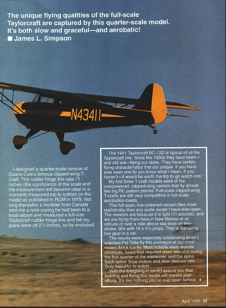
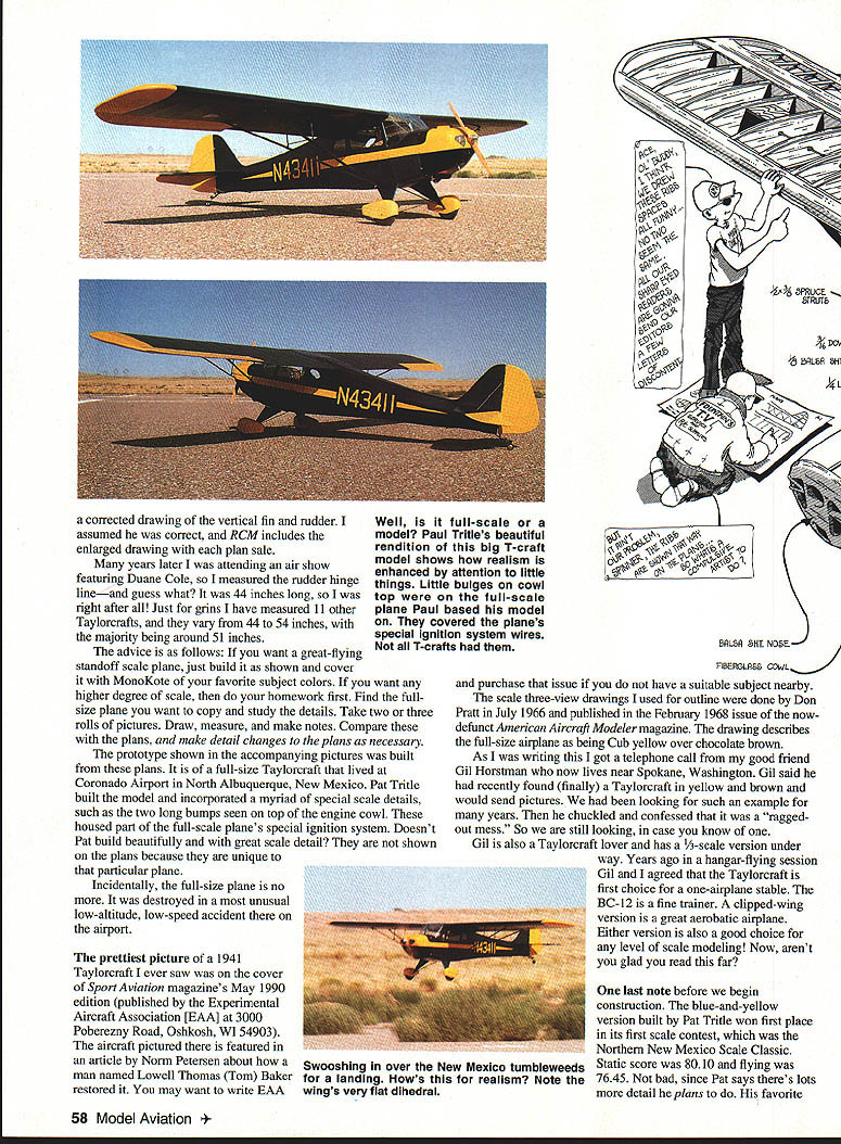
The prototype shown in the accompanying pictures was built from those plans. It was of a full-size Taylorcraft that lived at Coronado Airport in North Albuquerque, New Mexico. Pat Tritle built the model and incorporated a myriad of special scale details, such as the two long bumps on top of the engine cowl that housed part of the full-scale plane's special ignition system. They are not shown on the plans because they were unique to that particular plane. Incidentally, the full-size plane is no more; it was destroyed in a most unusual low-altitude, low-speed accident at the airport.
The prettiest picture of a 1941 Taylorcraft I ever saw was on the cover of Sport Aviation magazine's May 1990 edition (published by the Experimental Aircraft Association, EAA). The aircraft pictured there is featured in an article by Norm Petersen about a man named Lowell Thomas (Tom) Baker who restored it. You may want to write EAA and purchase that issue if you do not have a suitable subject nearby.
The scale three-view drawings I used for outline were done by Don Pratt in July 1966 and published in the February 1968 issue of the now-defunct American Aircraft Modeler magazine. The drawing describes the full-size airplane as being Cub yellow over chocolate brown. As I was writing this I got a telephone call from my good friend Gil Horstman, who now lives near Spokane, Washington. Gil said he had recently found (finally) a Taylorcraft in yellow and brown and would send pictures—but it was a "ragged-out mess." So we are still looking, in case you run across one.
Gil is also a Taylorcraft lover and has a 1/3-scale version under way. Years ago in a hangar-flying session Gil and I agreed that the Taylorcraft is first choice for a one-airplane stable. The BC-12 is a fine trainer. A clipped-wing version is a great aerobatic airplane. Either version is also a good choice for any level of scale modeling.
One last note: the blue-and-yellow version built by Pat Tritle won first place in its first scale contest, the Northern New Mexico Scale Classic. Static score was 80.10 and flying was 76.45. Not bad, since Pat says there's lots more detail than the plans show to do. Congratulations to Pat on such a great job—this model flies beautifully.
CONSTRUCTION
Tail
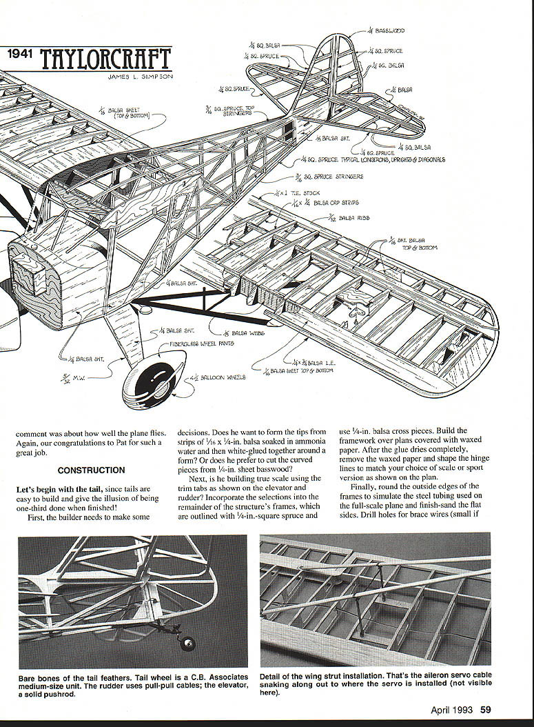
Let's begin with the tail, since tails are easy to build and give the illusion of being one-third done when finished.
Decisions:
- Do you want formed tips—strips of 3/32-in. balsa soaked in ammonia water and white-glued around a form—or cut curved pieces from 1/8-in. sheet basswood?
- If building true scale, incorporate the trim tabs shown on the elevator and rudder.
Construction:
- Use frames outlined in 1/8-in.-square spruce with 1/16-in. balsa cross pieces.
- Build the framework over the plans covered with waxed paper. After the glue dries, remove the waxed paper.
- Shape hinge lines to match your choice (scale or sport version shown on the plan). Round the outside edges of the frames to simulate the steel tubing used on the full-scale plane and finish-sand.
- Drill holes for brace wires (small if you plan to use 1/16-in. music wire) and install the tail wheel shown on the plan.
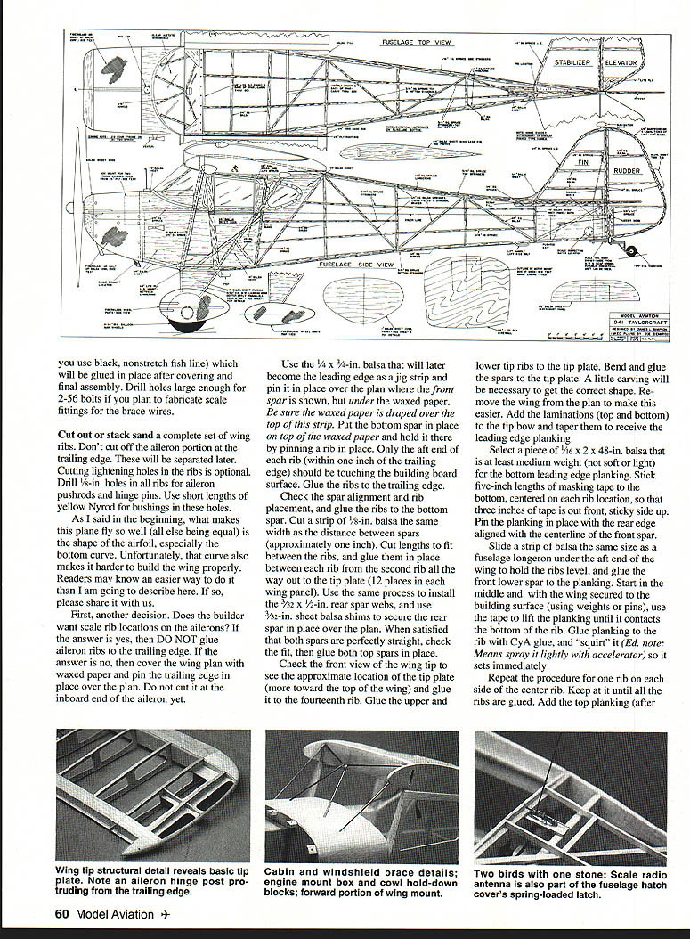
- If you use black, nonstretch fish line for rigging (glued in place after covering), drill holes large enough for 2-56 bolts if you plan to fabricate scale fittings for the brace wires.
Wing construction
Cut out or stack-sand a complete set of wing ribs. Do not cut off the aileron portion at the trailing edge; these will be separated later. Cutting lightening holes in the ribs is optional. Drill 1/16-in. holes in all ribs for aileron pushrods and hinge pins; use short lengths of yellow nylon for bushings in these holes.
The airfoil bottom curve (NACA 23012) makes the wing harder to build properly. The following is one reliable method:
- Decide whether you want scale rib locations on the ailerons. If yes, DO NOT glue the aileron ribs to the trailing edge. If no, cover the wing plan with waxed paper and pin the trailing edge in place over the plan (do not cut it at the inboard end of the aileron yet).
- Use a 1/4 x 3/4-in. balsa strip (that will later form the leading edge) as a jig and pin it in place over the plan where the front spar is shown, under the waxed paper. Ensure the waxed paper is draped over the top of this strip.
- Put the bottom spar in place on top of the waxed paper and hold it by pinning a rib in place. Only the aft end of each rib (within one inch of the trailing edge) should touch the building board surface. Glue the ribs to the trailing edge.
- Check spar alignment and rib placement, then glue the ribs to the bottom spar.
- Cut a strip of 1/8-in. balsa to the distance between spars (approximately 1 in.). Cut lengths to fit between ribs and glue them in place between each rib from the second rib all the way out to the tip plate (12 places in each wing panel).
- Install 3/32 x 1/2-in. rear spar webs the same way, and use 3/32-in. sheet balsa shims to secure the rear spar in place over the plan.
- When satisfied both spars are straight, fit and glue both top spars in place.
- Check the front view of the wing tip for the tip plate location (more toward the top of the wing) and glue it to the fourteenth rib. Glue the upper and lower tip ribs to the tip plate. Bend and glue the spars to the tip plate, carving as necessary to get the correct shape. Remove the wing from the plan to make this easier. Add the laminations (top and bottom) to the tip bow and taper them to receive the leading edge planking.
Leading edge planking:
- Select a piece of 1/16 x 2 x 48-in. balsa, medium weight, for the bottom leading edge planking.
- Stick five-inch lengths of masking tape to the bottom, centered on each rib location, so that three inches of tape is out on the front, sticky side up.
- Pin the planking in place with the rear edge aligned with the centerline of the front spar. Slide a strip of balsa the same size as a fuselage longeron under the aft end of the wing to hold the ribs level, and glue the front lower spar to the planking.
- Start in the middle and, with the wing secured (weights or pins), use the tape to lift the planking until it contacts the top of the rib. Glue the planking to the rib with CYA glue and use a light spray of accelerator so it sets immediately.
- Repeat outward until all ribs are glued. Add the top planking.
- Remove pins in front of the spar location and use "slow" CYA glue where needed. Use the free ends of the tape to secure the sheeting around the front of each rib; use tape or weights to secure the aft edge of the planking to the top spar. Let everything dry overnight.
- Remove tape and use a long (at least 11 in.) sanding block to sand the planking and rib fronts flat to receive the 1/4 x 3/4 x 48-in. balsa leading edge.
- Be sure the wing is flat, true, and will not move. Glue the leading edge in place and secure with pins or tape. Let the glue dry completely—this closes the structural "D" tube and sets the wing straight (or twisted if not aligned correctly) for life.
Aileron separation and reinforcement:
- Use an X-Acto saw and cut the ailerons loose by making the angled cuts through the ribs, then cut the trailing edge. Cut the rib stubs even with the back edge of the rear spar.
- Glue 1/16 x 3/4-in. balsa planking over the aft spar at the aileron cutout. Glue 1/16-in. triangle stock underneath. Add all cap strips top and bottom.
- Cut all strut mounts and doublers and install them. Do the same with the aileron bellcrank mount.
- Carefully remove the portion of the root rib between the top and bottom spars. Cut plywood spar webs 8-5/8 in. long; ensure the slight taper is on the bottom and toward the fuselage. Epoxy them between each set of spars.
- Add 1/16-in. sheet balsa planking and the hatch for the aileron servo as shown on the plan.
Ailerons and controls
Building the aileron:
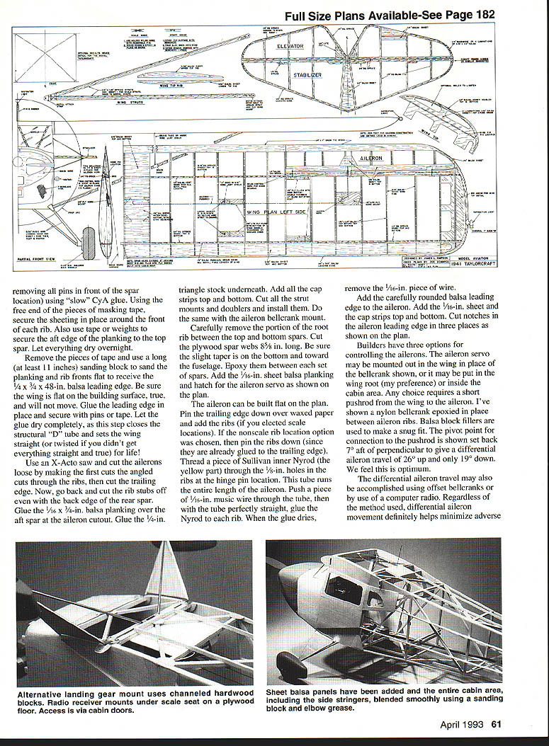
- The aileron can be built flat on the plan. Pin the trailing edge down over waxed paper and add the ribs (if you chose scale locations). If you chose nonscale rib locations, pin ribs down since they are already glued to the trailing edge.
- Thread a piece of Sullivan inner Nyrod (the yellow part) through the 1/8-in. holes in the ribs at the hinge pin location. This tube runs the entire length of the aileron.
- Push a piece of 7/16-in. music wire through the tube; with the tube perfectly straight, glue the Nyrod to each rib. When the glue dries, remove the 1/16-in. piece of wire.
- Add the carefully rounded balsa leading edge to the aileron. Add 1/16-in. sheet and cap strips top and bottom. Cut notches in the aileron leading edge in three places as shown on the plan.
Control options:
- The aileron servo may be mounted out on the wing in place of the bellcrank shown, in the wing root (preferred by the author), or inside the cabin area. Any choice requires a short pushrod from the wing to the aileron.
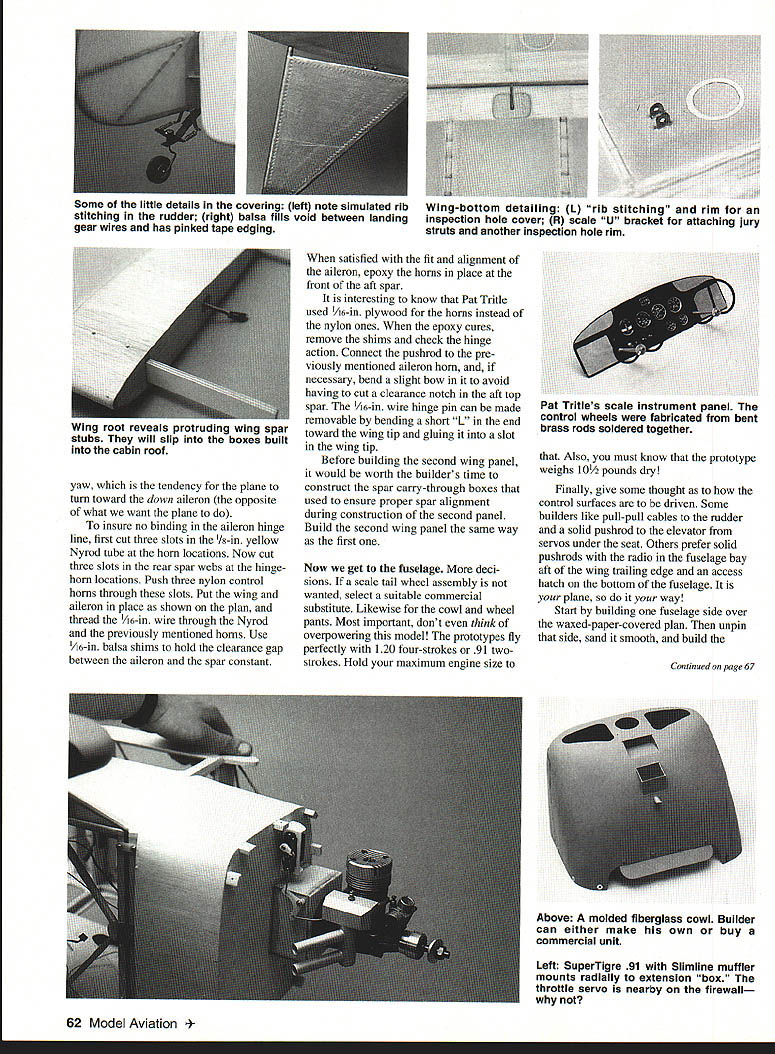
- The plan shows a nylon bellcrank epoxied in place between aileron ribs with balsa block fillers for a snug fit. The pivot point for connection to the pushrod is set back 7/8 in. perpendicular to give a differential aileron travel of 26° up and 19° down. This differential helps minimize adverse yaw (the tendency for the plane to yaw toward the down aileron).
- Differential aileron travel can also be accomplished using offset bellcranks or by a computer radio.
Hinge and horn installation:
- To ensure no binding in the aileron hinge line, cut three slots in the 1/8-in. yellow Nyrod tube at the horn locations, and cut corresponding slots in the rear spar webs at the hinge-horn locations.
- Push three nylon control horns through these slots. Put the wing and aileron in place, thread the 1/16-in. wire through the Nyrod and horns, and use 1/16-in. balsa shims to hold the clearance gap between the aileron and the spar constant.
- When satisfied with fit and alignment, epoxy the horns in place at the front of the aft spar. Pat Tritle used 1/16-in. plywood for the horns instead of the nylon ones.
- After epoxy cures, remove shims and check hinge action. Connect the pushrod to the aileron horn and, if necessary, bend a slight bow to avoid cutting a clearance notch in the aft top spar.
- The 1/16-in. wire hinge pin can be made removable by bending a short "L" in the end toward the wing tip and gluing it into a slot in the wing tip.
Before building the second wing panel, construct spar carry-through boxes to ensure proper spar alignment during construction. Build the second wing panel the same way as the first.
Fuselage
Decisions and considerations:
- If a scale tail wheel assembly is not wanted, select a suitable commercial substitute. Likewise for the cowl and wheel pants.
- Do not overpower this model. The prototypes fly perfectly with 1.20 four-strokes or .91 two-strokes. Hold maximum engine size to that. The prototype weighs about 10-1/2 pounds dry.
- Decide how the control surfaces will be driven: pull-pull cables to the rudder and a solid pushrod to the elevator from servos under the seat, or solid pushrods with the radio in the fuselage bay aft of the wing trailing edge and an access hatch on the bottom. It is your plane—do it your way.
Construction:
- Start by building one fuselage side over the waxed-paper-covered plan. Unpin and sand it smooth, then build the other side directly over the first with waxed paper in between. Remember these sides are framework only; sheet planking will be added later.
- Cut the 1/4-in. Lite Ply gear mount to fit between the lower fuselage longerons. It is 5-1/4 in. front to back. Use large pins or small nails to securely attach it to the building surface over the waxed-paper top view.
- Use right triangles to hold the fuselage sides vertical. Ensure tail posts are the same height above the bench—avoid building a twist into the fuselage.
- Before gluing the fuselage sides to the landing gear mount, sand the correct taper in the aft ends so that when pulled together the two sides are a total of 1/4 in. thick. Glue the longerons to the landing gear mount.
- Carefully cut fuselage crosspieces to length and glue them across the top of the cabin between the uprights that define the cabin doors. Use triangles to hold the cabin upright and square.
- Join the tail posts using a triangle to align them above the plan and hold the joint perfectly vertical. Add the remaining crosspieces and diagonals as shown on the plan.
- Note that the bottom longerons have a gentle curve and the top longeron has a definite "break" at the aft door upright. It may be necessary to crack that joint and reglue to get it right.
Engine and cowl
Mounting options:
- If a four-stroke or long-shaft engine is to be used, mount it on a radial mount directly to the firewall. Cut the firewall to shape and glue it to the front of the framework. Add 1/8-in. sheet balsa to the sides and bottom as shown on the plan. Mount the engine and install the fuel tank with the top third of the tank above the needle valve; secure the tank to prevent foaming when the engine runs.
- For most two-stroke engines (short), use a box with a square cutout in the firewall that extends back to the instrument panel. Mount the fuel tank inside this box (aft end open for access). The front of the box is 1/4-in. plywood. Bolt the radial engine mount to it. Cut the box length to position the engine's propeller drive washer about 1/8 in. ahead of the cowl. Build and fit the box to the firewall before mounting the firewall and adding 1/4-in. sheeting.
Cowl construction:
- If buying a fiberglass cowl, fit it to the plane, either flush with the firewall or overlapped as preferred.
- To make the cowl: use 3/16-in. or 1/8-in. balsa to rough in bottom and sides to fit between the firewall and the nose bowl. Since there is no compound curve in the top cowling, 1/8-in. balsa sheet may be formed by wetting one side to curve at the top; this top may be made removable if desired.
- Carve and sand the bottom and sides to match the plan or the specific full-size aircraft being modeled. The nose bowl is sheet balsa and must be carved and sanded to match the rest of the cowl. Balsa cowls may be bolted to the firewall cowl-mounting blocks like fiberglass ones.
Cabin roof, wing center section, and carry-through
- Key elements are the spar carry-through boxes and wing root ribs made of 1/16-in. plywood laminated to 3/16-in. sheet balsa. Make two root ribs exactly alike.
- Epoxy the front spar carry-through box to the top of the doubled spruce fuselage uprights. Fit and epoxy the root ribs and rear carry-through to the fuselage top side longerons and top cabin crosspieces.
- Carve a triangular-shaped balsa block to fill the gap between the root rib at the aft end of the rear spar carry-through and the top fuselage longeron. Add top fuselage stringers after the 1/4-in. square balsa crosspieces are installed.
Landing gear and struts
- Bend the landing gear from 3/32-in.-diameter music wire using the front and side views as guides. Remember the brace wire goes from each axle to the middle of the aft main wire.
- Clean wires where they will join, tin, bind with soft copper wire, and use plenty of heat to solder. Follow the proper order for best results.
- Fit the struts to the wing, then assemble the wing (with struts in place) to the fuselage with the whole assembly upside down on the workbench.
- Put a 1/2-in.-thick block under the cabin roof; with the wing tips touching the workbench, this gives the desired 1° dihedral when upright.
- With the wing taped in place, fit the main struts to the fuselage near the aft main gear strut point and install the hold-down bolts through the landing gear plate into large blind nuts.
- Set the plane upright, block up the tail, and check each main wing panel for proper incidence at least three places on each panel. If no warps are present, drill holes for four bolts (two through each root rib or one in each spar stub and carry-through box—builder's choice) to secure the wing panels to the fuselage.
Radio installation and final assembly
- Install the radio and all control linkages. Ensure all operate smoothly and in the proper direction.
- Add all structural scale details desired (gear-axle-to-wheel-pant attachment, wing strut cuffs) before covering. If fabric covering is used, it is better to wait until after covering before adding such details.
Covering and preflight
- The plane can be covered using your favorite method. Examples: Sig Koverall and dope; Coverite (not doped); or MonoKote. I have seen restored full-size Taylorcrafts so shiny they looked MonoKoted.
- Before flying, check for any warps and correct them. Do control checks for smoothness and proper direction. Use rate switches or exponential control to avoid overcontrol.
- Check the balance point to be sure it is as shown on the plans or slightly ahead. Run the engine and adjust the idle properly.
- Only when all of this has been done is the plane ready to fly.
This model flies like an Old-Timer free flight, except it also loops, rolls, spins, and flies inverted beautifully. If readers think all that is special, just hide and watch when I get the latest clipped-wing version done—they're really hot!
Transcribed from original scans by AI. Minor OCR errors may remain.

