


20 Hours Non-Stop!
Maynard L. Hill
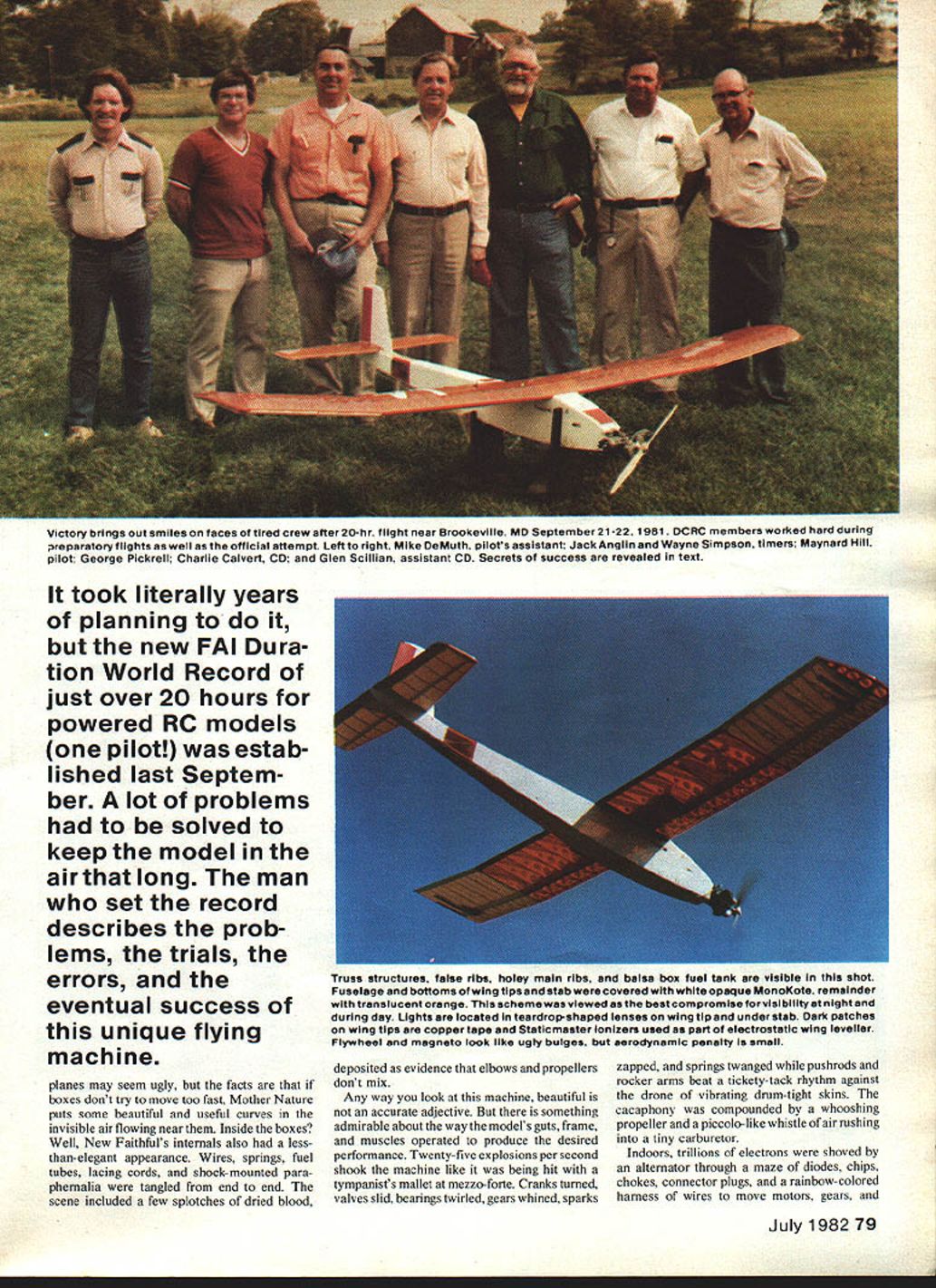
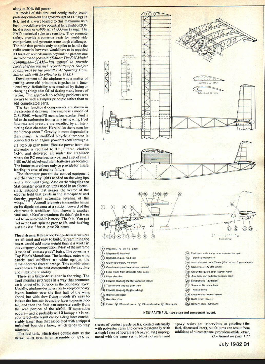
A few seconds before 5 p.m. on September 21, 1981, a radio-controlled model called New Faithful was launched from a pasture near Brookeville, MD, and was kept airborne through dusk, night, dawn, and morning until the engine was shut down at 1 p.m. on September 22. The regulations set up by the Fédération Aéronautique Internationale (FAI) were met, and the elapsed time of 20 hours and 51 seconds has been recognized as the current World Record for Duration. The preceding record, 16 hr. 43 min., had been established a few weeks earlier by a team of modelers headed by Dr. Plenny Bates of Cedar Rapids, IA.
When New Faithful was exposed for its first test hop at the local club field, one comic asked, "Did you really build it that way, or was it bent in a crash?" Another chirped, "It's an airborne anteater." Although this droop-snouted, boxy model was baptized with many such derisive comments, some of the joshers eventually acknowledged its functional beauty.
It is a descendant of Old Faithful, which set a World Duration Record with a flight of a mere 8 hr. 52 min. in 1964. Moreover, during the 1960s, similar droop-snouted, boxy machines set records for altitude (26,910 ft.), closed-course distance (184 mi.), cross-country goal distance (189 mi.), and duration (11½ hr.). In 1965, a tiny, clean version zipped through speed traps at 142 mph, and an immense unpowered "facsimile" soared to 3,660 feet in 1966. In all, 14 different World Records have been established by a family of birds that have been said to resemble tired pelicans flying upside down.
Enough of this disparagement. Squarish airplanes may seem ugly, but the facts are that if boxes don't try to move too fast, Mother Nature puts some beautiful and useful curves in the invisible air flowing near them. Inside the boxes? Well, New Faithful's internals also had a less-than-elegant appearance. Wires, springs, fuel tubes, lacing cords, and shock-mounted paraphernalia were tangled from end to end. The scene included a few splotches of dried blood, deposited as evidence that elbows and propellers don't mix.
Any way you look at this machine, "beautiful" is not an accurate adjective. But there is something admirable about the way the model's guts, frame, and muscles operated to produce the desired performance. Twenty-five explosions per second shook the machine like it was being hit with a tympanist's mallet at mezzo-forte. Cranks turned, valves slid, bearings twirled, gears whined, sparks zapped, and springs twanged while pushrods and rocker arms beat a tickety-tack rhythm against the drone of vibrating drum-tight skins. The cacophony was compounded by a whooshing propeller and a piccolo-like whistle of air rushing into a tiny carburetor.
Indoors, trillions of electrons were shoved by an alternator through a maze of diodes, chips, chokes, connector plugs, and a rainbow-colored harness of wires to move motors, gears, and lights. Linkages and incandescent lights glowed on each wing tip where atmospheric ions were also being interrogated to get reports on the bank angle. All this happened, not in the comfortable womb of a laboratory, but out in Mother Nature's soggy, foggy, bumpy atmosphere. It was a very gratifying experience to coax this machine through more than two million thumps without a missed beat.
This project was a hobby venture, extraneous to the author's profession, which deals with development of remotely piloted vehicles. The goal was "fly a long time," the approach was "keep it simple," the schedule was "whenever ready," and the motivation was "fun."
Some of the aeromodeling techniques and equipment employed may be of practical interest to those responsible for developing long-duration drones and unmanned vehicles (UVs) for communication relays, decoys, surveillance, electronic countermeasures, and other uses. The idea that model airplane technology might be used to reduce the cost of operational military systems was very popular in the early '70s, but mixed reviews of its merits have cropped up—because some of the goals and expectations went out of bounds. Perhaps this article will bolster this fundamentally sound idea. That would be a gratifying result. However, the inside and outside "secrets" of New Faithful will be exposed here primarily to help modelers and also to perhaps steer a few of them into the fun of breaking records.
Features of New Faithful
The crate-like appearance of New Faithful is a consequence of one FAI rule that limits all but Scale models to a gross takeoff weight of 5 kg (11.02 lb.). Aerobatic and racing models seldom approach this limit, but for duration models, this restriction means that the only way to increase fuel capacity is to decrease structural weight. Engine displacement is limited to 10 cc (0.61 cu. in.), and the lifting surface area (wing and tail) is restricted to 1.5 m^2 (16.15 sq. ft.), but neither of these rules influenced this design. The wing was sized to fit inside a Toyota Hatchback, and although the largest permissible engine was installed, it normally loafed along at 20% full power.
A model of this size and configuration could probably climb out at a gross weight of 11+ kg (25 lb.), and if it were loaded to this maximum with fuel, it would have the potential for a flight of 200-hour duration or a 6,400-km (4,000-mi.) range. The FAI's technical rules are sensible. They promote safety, provide a common basis for worldwide comparison, and generate some tough challenges. The rule that permits only one pilot to handle the radio controls, however, would have to be repealed if duration records much beyond the present one are to be made possible. (Editor: The FAI Model Committee—CIAM—has agreed to provide pilot relief during such record attempts. Subject to approval by the overall FAI Sporting Committee, this will be effective in 1983.)
Development of the airplane was a matter of putting some old principles together in a functional way. Reliability was obtained by fixing or changing things that failed during many hours of testing. The approach to solving problems was always to seek a simpler principle rather than to add complicated parts.
The key functional components are shown in the structural drawing. The engine is a modified O.S. FS60, where FS means four-stroke. Fuel is fed to the carburetor from a tank in the wing. Fuel flow rate and pressure are steadied by an interdicting float chamber. Herein lies the reason for the "droop snoot." Gravity is more dependable than pumps. A modified bicycle alternator is connected to an engine power takeoff through a 2:1 step-up gear train. Electric power from the alternator is rectified to d.c., filtered, choked (RF), and delivered aft under the stabilizer where the RC receiver, servos, and a set of small (100 mAh) nickel-cadmium batteries are located. The batteries are there only to provide for a safe landing in case of engine failure.
The alternator powers the control equipment and the three tiny lights needed on the wing tips and tail for night flying. Also on the wing tips are Staticmaster ionization units used in an electrostatic autopilot that senses the vector of the electric field that exists in the atmosphere and thereby provides automatic leveling of the wings. A small telemetry transmitter hangs on its dipole antenna at a station forward of the electrostatic stabilizer. Not shown is another vital unit: a Kraft transmitter, which for this flight was tied to an automobile battery. That's it. You put fuel in the tank, spin the prop to life, and the thing sustains itself for at least 20 hours.
The airframe
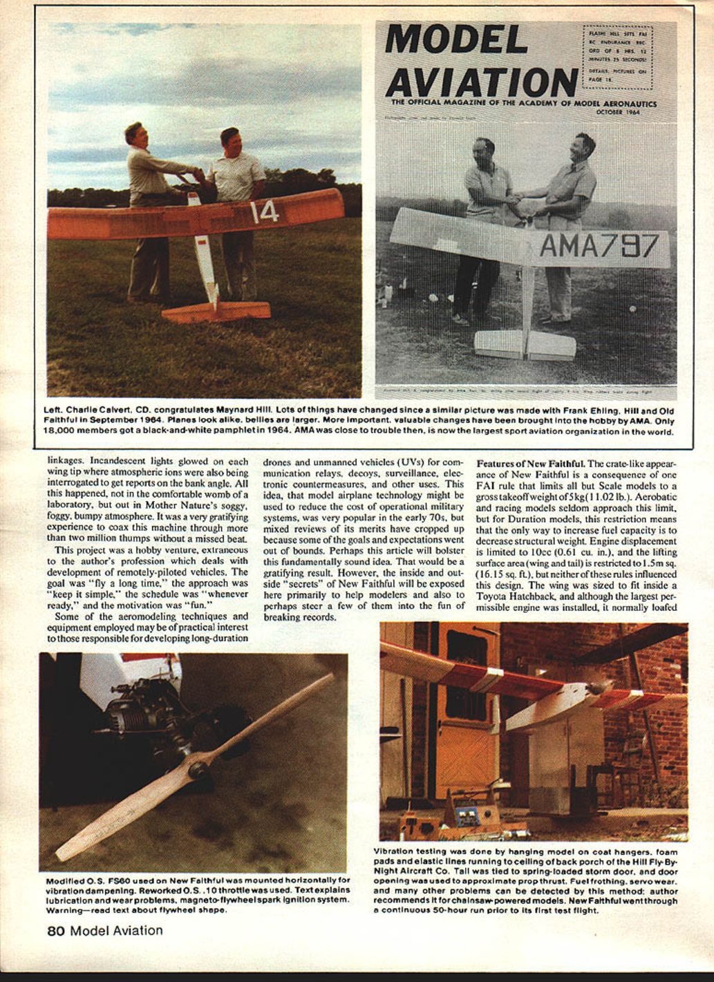
Balsa-wood bridge-truss structures are efficient and easy to build. Streamlining the boxes would add more weight than it is worth in this category of competition. Most of the airframe is made of "contest grade" balsa. The covering is Top Flite's MonoKote. The fuselage, outer wing panels, and stabilizer are white opaque; the remainder translucent orange. This combination was chosen as the best compromise for daytime and nighttime visibility.
There is a bridge-truss spar in the wing. The front member protrudes in a way that promotes early onset of turbulence in the boundary layer. Usually, airplane designers try to keep the boundary layer laminar over the first half of the wing chord, but with slow-flying models it's easy to induce the laminar boundary layer to persist too far, and then the flow can separate easily from the rear portion of the airfoil. If separation occurs—and it probably will if bumpy air is encountered—the result can be a drag force considerably larger than that associated with a tripped turbulent boundary layer, which tends to stay attached.
The fuel tank, which does double duty as the center wing spar, is an assembly of 1/16 in. sheets of contest-grade balsa, coated internally with polyester resin and covered externally with a single layer of fiberglass (3/4 oz./sq. yd.) impregnated with the same resin. Most polyester and epoxy resins are impervious to gasoline (the fuel, discussed later), but failures can result from additions of nitromethane, propylene oxide, ether, and other useful ingredients.
To avoid building a wing spar that might dissolve in its contents during flight, many samples of balsa were coated with a variety of resins and placed in baby-food jars containing candidate fuels. The array of samples was stored for months in a backyard greenhouse. This exposure to thermal cycling and solvents was a brutal test. Some combinations that looked satisfactory during winter turned into messes in July. Sig Mfg. Co.'s polyester finishing resin was eventually chosen. K&B finishing resin fared equally well in the test. Scale modelers using chainsaw engines might find this idea useful. It's OK with gasoline, but I haven't found any resins that will resist fuels containing nitromethane or ether and other useful ingredients.
Engine modifications
The O.S. FS60 engine, as received, is designed to use glow-plug ignition and regular alcohol-based model fuel. Gasoline is far more efficient than alcohol, but glow-plug ignition doesn't work well with gasoline-based fuels unless the compression ratio is increased to the point where the mechanical problems are severe. Furthermore, fuel-air mixtures become extremely critical and sensitive to temperature and humidity changes. I toyed enough with such ideas to reach the conclusion that spark ignition, even with its heavy coils and radio-interference problems, was bound to be a better method. So, a magneto coil and flywheel from a grass trimmer engine (Lawn Boy, part #06823-07, -08) were mounted on the front housing.
The flywheel was originally round, but it was cut to a dumbbell shape to reduce weight. Warning: don't try this dodge on an engine that turns up to the usual 9,000 rpm. The dumbbell will fly apart. To prove it, I have a paint can with a hole in it and a waste basket with a large bulge. There was sand in the annulus between these containers. Some of the sand flew out the top when the flywheel broke. Taking fatigue into account, I wouldn't trust this thing above 5,000 rpm. Top speed of this engine with the 16 x 10 hand-carved propeller was around 4,500 rpm.
The coil is called a solid-state magneto. The spark discharge is triggered by the same magnetic flux that energizes the coil. The inner secrets of this device seem to be proprietary, but two important observations can be made without knowing exactly how it works: 1) there are no points to wear out, and 2) it generates a milder form of radio-frequency noise than do either point systems or capacitance-discharge systems. The RF noise can be effectively suppressed by putting a 10 kΩ resistor in series with the plug and by putting a shield over the high-tension lead.
Until about 1979, all engines being mass-produced for hobby use were of the two-stroke type, and until this flight in 1981, all World Records in all Power categories had been established with such engines. Although I had experimented earlier with homemade four-stroke engines (which have better fuel efficiency), perfecting an engine for duration takes lots of spare parts, so no serious effort was made to use such a design until the O.S. FS60 appeared. This engine is remarkably well built. I have run one more than 400 hours, and bearings, piston, fit, and compression are practically as good as new.
Some problems, however, showed up in the valve/rocker-arm/cam system, partly because very little lubrication was being used in an effort to attain high fuel efficiency. Valve clearances had to be reset every three hours, and after 24 hours the pushrods were too short to permit further adjustment. This problem was partially fixed by weakening (shortening) the valve springs and replacing the pushrods with pieces of Allen hex-wrench material (5/64 across the flats). The tips of these pushrods and the tips of the cam-follower pins were hardened by heating them with a microtorch to about 1,600°F (near an orange glow) and quenching with water. No annealing or tempering was done after the quench.
Next, the valve drive came to an end. This problem was mitigated by adding oil to the fuel and drilling a small breather hole in the cam case aft of the cam. Oil was, thereby, blown through the cam housing. This splattering oil made a new black mess inside the model's nose, but now the valve system was good for 50 hours between adjustments. On to the next problem!
Carbon build-up on the valves and spark plugs choked the engine to a stop in about 10 hours unless I baby-sat and gradually backed out on the mixture needle valve. Here, we reached into an old bag of tricks for polysobutylene, a chemical used in the manufacture of synthetic rubber. This viscous liquid does a pretty good job of lubricating valves, and instead of producing carbon particles, it cracks mostly into combustible hydrocarbon molecules when heated. Perfect! Very little carbon is formed, and fuel efficiency is increased. The composition of the fuel was 93% premium-grade automotive gasoline, 6% polysobutylene, and 1% diethyl ether.
The most tedious work dealt with the carburetor. A standard RC-type needle valve could have been installed, but would have defied the simplicity rule. Besides, my hearing is poor, and the U.S. FS60 is a very quiet engine. Instead, a built-in means of keeping fuel-air ratio constant throughout the power range was sought. A carburetor from a 1.5 cc (O.S. .10) engine was adapted to the inlet manifold. A mercury manometer was attached to monitor inlet-manifold pressure, and fuel was fed to the engine via a float chamber from a 50 cc graduated burette. The needle valve was first adjusted for lean but smooth running at full throttle. From periodic readings of the rpm, manifold pressure and the fuel level in the burette, a number proportional to the fuel-air ratio was calculated. Additional sets of data were recorded for lower throttle settings. The fuel-air ratio never came out constant with a stock carburetor. Usually, the mixture became very rich at low power.
A peculiarly shaped notch in the carburetor barrel was needed. The notch shape was found by grinding a little, testing the fuel-air ratio over the whole rpm range, grinding a little more, testing again, etc. I got it right on the third carburetor on the fifth weekend. It was during this long procedure that I got absent-minded and forgot there was a propeller revving on the front. Ouch!
Shake, shake, shake. Eventually, a continuous "hands-off" run of 50 hours duration was made. For this run, the engine was mounted on the aircraft, which was suspended on elastic lines to allow the entire flight-ready assembly to vibrate as if airborne. One often hears the builder of a new airplane exclaim, "It flew right off the drawing board." That effusion signifies bad practice. You really ought to hang up a new model and shake it about 15 minutes per pound before trying to fly it.
Controls and electronics
In the fuselage, the radio equipment, which consisted of a Kraft 53.3 FM receiver and Ace Bantam Midget servos, was placed far aft to reduce the chances that ignition noise would cause jitter and excessive current drain by the servos. As it turned out, this precaution was not really necessary, because very effective shielding was eventually installed. The nickel-cadmium batteries, a special Hi-Rate type obtained from Ace Radio Control, can withstand severe overcharging, so there was no need for a voltage regulator.
The telemetering unit sensed the current flowing into or out of the batteries, and a monotonous musical note from the ground-based receiver gave pleasant assurance that all was well on board. Servo motions could be detected as a superimposed buzz, and since the charging current changed with engine rpm, the pitch of the tone indicated engine speed. Interference or glitching due to weak signals could also be detected by the presence of a scratchy noise, but this ominous sound wasn't heard during the record flight.
The polyhedral of the wing minimizes spiral instability of the basic model, but fuel shifting from one side of the wing to the other during uncoordinated turns generates quite a load of rudder work for the pilot. So, an electrostatic stabilizer (refs. 7–10) was used for automatic wing leveling. The total weight of this system was 1¼ oz., equal to more than an hour's worth of fuel—but a good trade. Devices of this type can also be used to stabilize pitch attitude, but this feature was omitted in this instance. Instead, a long tail and large stabilizer were used. This simple expedient provided a substantial margin of inherent pitch stability and precluded potential troubles related to servo wear and extra current drain in an active pitch-stabilization loop.
Practice and preparations
For trials to work the "air bugs" out of the system, all of the components were installed in a model made from relics left over from 1960s record attempts. In flights during dusk and dawn periods, the airplane cannot be seen very well, but neither is it dark enough to see the small red, green, and white navigation lights. The electrostatic stabilizer was found to be a big help during these periods, as well as during the night when visual determination of the attitude of the airplane was based solely on the orientation of the three tiny incandescent bulbs.
At the planned flight altitude of about 1,500 ft. above the ground (or 2,000 ft. above sea level), the array was closely spaced, the color contrast was not strongly discernible, and staring at these star-like wanderers among Orion and other rocks of the heavens had a hypnotic effect that mesmerized even the most keyed-up senses. My limit was three or four hours. However, an FAI rule states that no assistant pilots are allowed to use the control transmitter. The electrostatic stabilizer served very effectively toward overcoming this roadblock. Instead of having to pay attention and compensate for spiral instability, I was able to close my eyes, relax on a chaise lounge, and momentarily pulse the control stick hard over in response to verbal commands from observers who could do the staring in relays. So that cat was skinned.
The pretested equipment was transferred into a new airframe for a July 4 baptismal flight. By mid‑August, the assembly had been tortured for 75 hours on the ground and 25 hours in the air, and confidence in the machine was very high. The remaining task of flying 20 or so hours for official witnesses would call for some truly dedicated people. "Exciting boredom" is what John Worth called it during a previous (1964) record flight. Care was taken to pick helpers and officials whose qualities included patience, stamina, and a sense of humor.
Weather loomed as the last barrier. The model is strong enough to withstand fairly severe turbulence, but to avoid unpredictable thunderstorms and to keep the pilot's work to an acceptable level, it seemed wise to wait for the calm that is a characteristic of equinoctial highs (convectively stable masses of hot air) that frequently stagnate in our area during the last half of September. Synoptic weather information from many sources was watched for the signs that usually precede the favorable conditions. September 2 and 3 were great, but the crew and officials were off in Bealeton, VA, running the DCRC's annual Scale competition. Wouldn't you know!
This year a series of rapidly moving cold fronts followed. On September 20, the crew gathered under drizzling clouds and went through a test run of official weighing, launching, and timing procedures. The next afternoon, an occluded front stretched east-west from Kansas City to Philadelphia, with rain 100 miles north of our area. We decided to see how far we could get even though there was a 15-mph wind from the southeast and a partial overcast of gray stratocumulus clouds. Usually, such conditions get worse before they get better. Rain and high winds were expected unless the front changed its direction.
The record flight
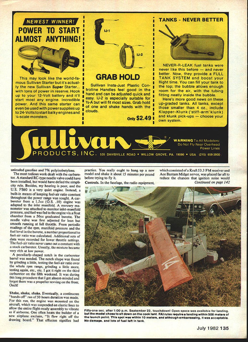
The launch went off as planned at 5 p.m. By sundown (7:30 p.m.) the clouds had cleared and the wind was dead calm on the ground, but there was obviously some flow at 1,500 ft., for the model sat nearly stationary, its airspeed matching the wind. We had not flown it here to the east of the field earlier, and by 8:30 p.m. the observer motion was working well in a clear, star-laden sky.
Two artificial satellites were seen about this time. The boredom was relieved by philosophical discussions inspired by these sightings. A couple of old Sputnik jokes came out of the woodwork, too—like, "Hey, did you hear that the Russians put 10 cows in orbit? They say it's the herd that was shot 'round the world."
By midnight, the observers were so practiced at giving yaw and pitch trim commands that they were competing to see who could hold this new constellation stationary for the longest period. There were long times when it could be mistaken for a star. I got a little sleepy and missed a few commands. To stir my attention, George Pickrell jumped up onto a box and bellowed, "Holy cats! There are three guys coming over the hill on camels!" There's nothing like a healthy guffaw to keep a party alive.
About 2 a.m. a heavy ground fog formed. It stayed through the night, but never grew thicker than about 75 ft. Sideways visibility was only 50 ft., and there would have been no way to accomplish a safe landing if the engine had failed. Vertically, the navigation lights and stars could be seen through a cone-shaped hole.
By 5 a.m., the wind aloft had shifted to the west. Hooray! The front was moving away. The visibility cone, however, had diminished to about a 20° included angle. Ground equipment, crew, and blankets were soaked with dew, and tension was building because we had never flown through a very foggy dawn. With six pairs of eyes and two pairs of field glasses, we made it.
By 9 a.m., thermal convection and winds (about 10 mph at ground level) were causing the model to bounce more, so the nighttime observer procedure had to be abandoned. By 10:30, husky bumps were causing excessive currents in the electrostatic stabilizer system, so that aid had to be shut down. At 1 p.m. we were 3½ hours past the prior record. The airplane was performing admirably; the telemetry was saying everything's fine. I was grumpy over the one-pilot rule, but otherwise I felt OK.
A landing more than 500 meters from launch would scrub any record claim. I decided we'd done enough, and pushed the engine-shutdown button. A gust blew the airplane onto a collision course with my wife's shiny new Honda during the final approach. In the interest of continued harmony, there was no choice except to pull up, over her car. The model was ignominiously impaled on a corner pole of the cook tent, 10 meters from the launch point. We were home, nonetheless, with a valid claim to the record.
Inferred results and their implications
The gross takeoff weight of this model was 4.98 kg (10.96 lb.). Of this, 1.73 kg (61 oz.) was fuel. When the model landed, a little more than half—0.89 kg (31 oz.) of the fuel—was still in the tank. Thus, this model has a theoretical capability for a flight in excess of 40 hours. The model's "gas mileage" figure is 1,500 mpg, and its estimated "FAI legal" range (without wind) is nearly 1,000 miles.
The fuel consumption rate of 42 g/hr (1.5 oz./hr.) is impressively low, but there is no miraculous engine efficiency involved in this performance. As evidence, consider the following points. The model was flown at about 25 mph through most of the flight. It probably has a lift-to-drag ratio of about 10 at that speed. Assuming propeller efficiency of about 0.75, the specific fuel consumption can be calculated to be about 1.03 lb./hp·hr. This rate is about 10 times smaller than what goes into two-cycle engines on alcohol, but it is still nearly twice that of some larger four-cycle engines used on manned aircraft. Further improvements in the engine are, therefore, theoretically possible, but they would not be easily achieved in this small size.
It is interesting to speculate what kind of performances might be obtained by an all-out "legal FAI" model. Suppose, for example, a spindly, toothpick monster model of utmost structural efficiency was made instead of this fairly robust one. Also assume the use of carbon fibers, Kevlar, titanium, samarium-cobalt magnets, lithium batteries, solar cells, and tough microfilm coverings. Further, make it a tandem wing of maximum allowable area, and (of course) install a lightweight electrostatic pitch stabilizer to allow equal loading of both surfaces. Work on improving the specific fuel consumption, and fly at a still slower speed. How long might it fly? Two hundred hours seems possible. How far? Capability for a non-stop San Francisco to Boston flight would be a reasonable expectation and, for that matter, so would a New York to Paris flight.
But there would be some very difficult logistical problems associated with any such attempts. I have absolutely no interest in trying to prove I can stay awake longer than somebody else—so I'm inclined to try something easier, like turning one of those electrostatically stabilized machines loose at the upper end of the Grand Canyon. The terrain-avoidance features of the stabilizer would automatically steer the machine down the valley. We'd launch at Moab, Utah, hop a jet to the Hoover Dam, and sit in a bar telling flying stories while waiting for the machine to arrive a day later.
Another dream, another time!
Acknowledgements
The officials and observers provided valuable help and encouragement not only during the record flight, but also during preparatory test flights. I am very grateful for the patience, humor, and hard work contributed by Mr. Charles Calvert, Contest Director; by Mr. Wayne Simpson and Mr. Jack Anglin, timers; and by Messrs. Michael DeMuth, George Pickrell, and Glen Scillian, official observers and pilot's assistants.
Helpful advice about lubrication problems was obtained from Mr. Don Lindley of the Amoco Research Laboratories, and Mr. Ray Cramer provided useful consultations on aerodynamics. Valuable technical assistance was contributed by members of the District of Columbia Radio Control Club (DCRC). In particular, Mr. Ben Givens worked on the telemetry devices, and Messrs. Melvin Newcomer, William Charbonneau, and Robert Lee assisted in the design and fabrication of the electrostatic stabilizer and other electronic units. Mr. Paul Nast granted the use of runways at his gliderport at Brookeville, MD. This facility was a valuable asset to the project.
Mrs. Lillian Goldfinger, Johns Hopkins University, Applied Physics Lab (APL), made useful suggestions and patiently typed badly scribbled drafts. Dr. Gordon Dugger (APL) edited and improved the original manuscript. This effort was greatly appreciated.
References
- Hill, M.L., "Beat the Russians or Bust," Model Airplane News, Vol. 72, No. 1, Feb. 1965, p. 28.
- Hill, M.L., "27,000 Feet, It's Catbird Country," Flying Models, #406, Jan. 1971, p. 18.
- Hill, M.L., "Shuffle Off to Buffalo," Model Airplane News, Vol. 73, No. 2, Feb. 1966, p. 30.
- Hill, M.L., "1-1/2 Hours of Exciting Boredom," Flying Models, #390, Sept. 1969, p. 6.
- Hill, M.L., "Tortoise, World Speed Record Model," Flying Models, #359, Jan. 1967, p. 20.
- Hill, M.L., "Boon Boomer, World Record Soaring Glider," Flying Models, #360, Feb. 1967, p. 9.
- Hill, M.L., "Introducing Electrostatically Stabilized Autopilots," Astronautics and Aeronautics, Vol. 10, No. 11, Nov. 1972, pp. 22–31.
- Hill, M.L., "Electrostatic Autopilot for R.C. Models," Flying Models, #431, Feb. 1973, p. 20.
- Hill, M.L., "Design and Performance of Electrostatically Stabilized Delta Platform Mini RPVs," Conference Proceedings, Military Electronics Defense Exposition, Wiesbaden, Germany, Oct. 1977. Interavia SA, Geneva, Switzerland, pp. 847–861.
- Hill, M.L.; Whyte, T.R.; Weiss, R.O.; Rubio, R.; Isquierdo, M., "Use of Atmospheric Electric Fields for Vertical Stabilization and Terrain Avoidance," Proceedings of AIAA Guidance & Control Conf., Albuquerque, N.M., August 19–21, 1981. AIAA Paper #81-1848-CP.
Transcribed from original scans by AI. Minor OCR errors may remain.

