
.21 Fun Speed
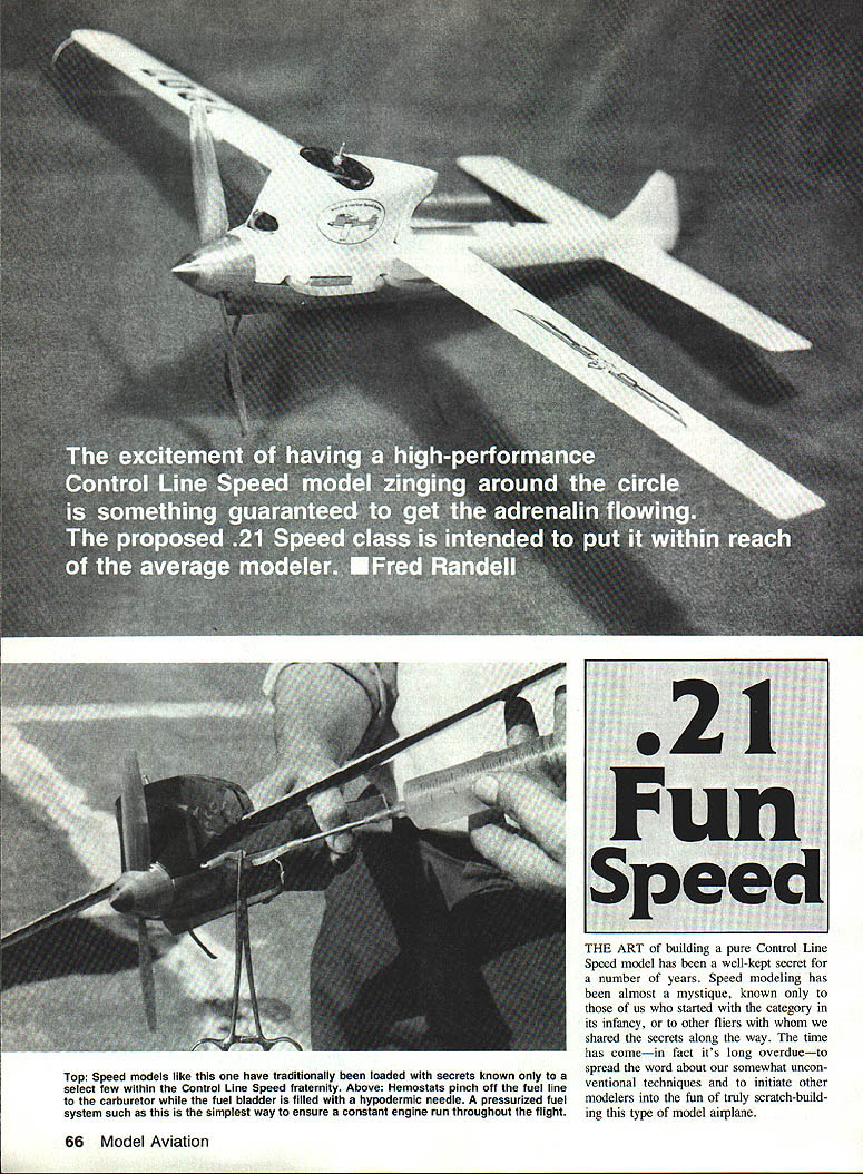
The art of building a pure Control Line Speed model has been a well-kept secret for a number of years. Speed modeling has been almost a mystique, known only to those who started with the category in its infancy or to other fliers with whom we shared the secrets along the way. The time has come — in fact it's long overdue — to spread the word about our somewhat unconventional techniques and to initiate other modelers into the fun of truly scratch-building this type of model airplane.
First, let's review the proposed rules for the .21 Sport Speed classification. Although these have been presented before in various publications, in each case some points were either left out or not addressed properly. The rules are as follows:
Rules for the .21 Sport Speed classification
- Intention — This event is intended to be a low-cost, low-key Speed class for novice fliers and to allow anyone who is physically able to pilot the model. Although open to anyone interested in Speed flying, the event is promoted chiefly for the benefit of newcomers, with the goal of introducing beginners to the class.
- Engine — The engine shall be of .21-cu.-in. displacement and shall operate on an "open face" or minipipe exhaust system only. Modification of engines is permissible, but no hybrids or crossbreeding of engines are allowed.
- Airplane — The model shall be of standard symmetrical design and outfitted with either upright or inverted engines. The fuselage shall be of standard full-fuselage design, with or without a speed pan. No profiles! The maximum amount of asymmetry from left wing to right shall be 1 in. The engine shall be fully cowled and the model attractively finished. No permanently attached landing gear is required, encouraging the use of a takeoff dolly instead; however, using a single-wheel gear is optional.
- Lines and control system — The model shall operate on a two-wire control system only, with a minimum line diameter of .016 solid strand. Length shall be 60 ft., 0 in., measured from the centerline of the airplane to the centerline of the handle grip. The lines must be connected outside the wing tip of the model with Pylon Brand link connectors, Stock No. 149, 110-lb. test, or the equivalent. The lead-out wire shall be stranded cable, Pylon Brand No. 145 stainless steel or the equivalent.
- Fuel — Contest-supplied 10% nitro maximum with 20% oil (1/2 castor and 1/2 synthetic recommended).
- Timing — The model shall be timed for seven laps after three laps have been completed in the pylon. All other timing procedures shall follow those of AMA Class A Speed.
- Propeller — May be of any manufacture, but shall be restricted to standard two-bladed design. No single bladers.
- Fuel system — No restriction is placed on fuel delivery. Suction type, crankcase pressure type, or bladders are allowed.
- Pull test — The airplane and its control system shall withstand a pull test of 40 G's (2-1/2 pounds per ounce of model weight).
Tools and materials
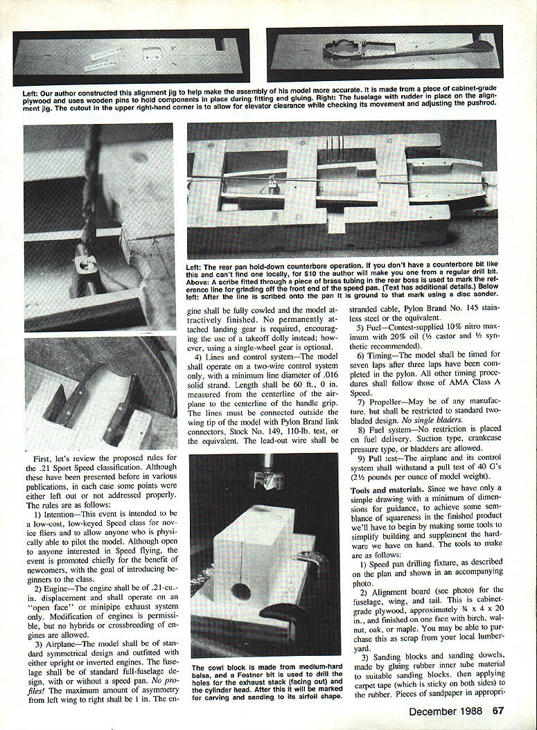
Since we have only a simple drawing with a minimum of dimensions for guidance, to achieve some semblance of squareness in the finished product we'll have to begin by making some tools to simplify building and to supplement the hardware we have on hand. The tools to make are as follows:
- Speed pan drilling fixture, as described on the plan and shown in the accompanying photo.
- Alignment board (see photo) for the fuselage, wing, and tail. This is cabinet-grade plywood, approximately 3/4 x 4 x 20 in., finished on one face with birch, walnut, oak, or maple. You may be able to purchase this as scrap from your local lumberyard.
- Sanding blocks and sanding dowels, made by gluing rubber inner-tube material to suitable sanding blocks, then applying carpet tape (which is sticky on both sides) to the rubber. Pieces of sandpaper in appropriate grits. Model cement holds the sandpaper directly on the dowels.
- Wooden swab sticks. May be purchased at most pharmacies or TV parts stores.
The standard tools and adhesives you'll need for the project are listed at the end of this article. There's no reason you can't use simple hand tools alone, but that will prolong your building time. It's worth your while to seek the help of someone with the appropriate power tools such as a drill press, band saw, disc sander, and lathe. Those still in school may find that shop teachers are willing to assist with cutting and shaping some parts. Another source is a local cabinetmaker. Also, your local hobby shop should know of customers who own machine tools to help with the tough cuts; most model builders are more than willing to assist if asked.
For the most part, the required building materials listed below can be purchased from your local hobby shop or from advertisers in this magazine:
- One sheet basswood, 1/2 x 3 x 36 in., for the fuselage crutch
- Two sheets basswood, 1/4 x 3 x 36 in., for the wing and crutch top
- One sheet soft balsa, 1/4 x 3 x 36 in. (if you choose to laminate the cowl)
- One piece basswood, 1/8 x 3 x 36 in., for wing-and-fuselage-to-cowl spacer
- One sheet medium-grade balsa, 1/4 x 3 x 36 in., for stabilizer
- One piece mahogany, 1/2 x 2 x 12 in., cut into strips to outline the wing and stabilizer
- One piece each 3/32-in. I.D., 1/16-in. I.D., and 3/64-in. I.D. brass tubing
- One piece .057-in.-dia. music wire
- Two quick-disconnect clevises (such as Du-Bro)
- Two pushrods, threaded on one end
- Class A or B speed can, Darp or equivalent brand
- Steel plate, 1/2 x 1/4 in. and .050 or .055 in. thick, for the bellcrank
A list of specialty parts suppliers is included at the end. Possibly more complete and current information could be obtained by attending a local CL Speed contest and asking contestants where they obtain their supplies.
Construction
Construction begins with selection of the engine and speed pan. This Sport Speed model can be powered with any .21 cu.-in. (3.5 cc) engine sold for aircraft use. Once you've chosen your engine and speed pan, begin fitting one to the other.
First order of business is to obtain a flat surface on the pan to make it suitable for mounting the engine. A good method for achieving this is to use medium-grit sandpaper taped to a sheet of glass, which in turn is secured to your work surface with carpet tape. Move the flat side of the pan back and forth against the sandpaper until no valleys remain.
The problem of achieving squareness of the pan front end is solved with the scribe and grinding as sketched on the plan. Measure across the rear hold-down boss, mark the center, and drill with a No. 43 bit (we will tap it for 4-40 threads later). Cut a piece of music wire 12 in. long, grind a point on one end, and make a 90° bend 1/2 in. from the point.
Cut a 1/2-in. length of 3/32-in. brass tubing, then drill a 1/16-in. hole at a 90° angle to the tubing length and 1/8 in. from one end. Slip the music wire into this hole; it should be a force fit. The brass tubing will now pivot in the No. 43 hole in the rear hold-down boss. Adjust the music wire length as necessary, and use the scribe to draw an arc at the front. Connect the extremities of the arc with a straight line, which becomes the reference for grinding off the pan front end.
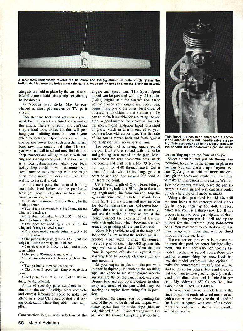
Note: It is possible to adjust the length of the scribe fixture so that the scribed arc will produce a pan width to match the spinner size you plan to use. (The OPS spinner fits very well on a Rossi .21.) When the pan front is squared off, double-layer it with masking tape to provide clearance for engine mounting.
Set your engine in place on the pan with a spinner backplate just touching the masking tape, and check to see if the engine mounting lugs are flat on the pan. If not, use your Dremel tool and appropriate cutters to clear away any areas of the pan which may be keeping the engine from sitting flat in position.
To mount the engine, start by painting the area of the pan to be drilled and tapped with either layout fluid or model dope (blue or red) thinned 50-50. Place the engine on the pan with the spinner backplate just touching the masking tape on the front of the pan. Select a drill bit that just fits through the mounting holes. With the engine in place on the pan (you can use a drop of cyanoacrylate (CyA) glue to hold it), insert the drill through the holes and rotate it a few times to make an impression in the paint. With all four hole centers marked, place the pan securely in a drill jig and very carefully center-punch where the drill made its marks.
Using a drill press and No. 43 bit, drill the four holes at the center-punched marks (5/16 in. deep), then tap for 4-40 threads. Make sure you use a sharp (new) tap. If this process is new to you, get help and advice.
At this point you can also drill and tap the holes for the airframe (top) hold-down bolts. You may want to counterbore for the brass alignment tubes that will be fitted through the fuselage later.
The counterbore procedure is an extra refinement that produces better fuselage alignment and isn't necessary for holding the model together. A second counterbore for the screw heads is also optional. I like counterbores myself, and will be glad to do so for others. Just send the drill to me and I'll be happy to drill them. My address is 659 Colony Rd., Box 7305, Canal Fulton, OH 44614.
Alignment fixture and fuselage crutch
The alignment fixture is made from a flat piece of cabinet-grade plywood and marked with a centerline. Make sure that the end of the board is square with one of its sides. Mark the centerline so that it runs parallel to that same side.
Fuselage crutch: Mark a centerline on the wood you will be using for the crutch; mark a perpendicular line where the front of the pan will be. Center the pan over the centerline of the crutch, and trace the outline of the pan. Measure where the bosses of the pan occur, and leave equal amounts of wood in these areas.
Draw the outline of the bottom section of the engine crutch in its proper relative position. Provide for 3/8-in. crutch walls all around (except that the crutch is left intact from the engine backplate to the wing leading edge for strength, and the hold-down bosses should have at least 3/8-in. of rounding wall). Cut and sand the crutch outline to shape.
Mark both ends of the crutch to show the centerline. Place the crutch blank over the centerline of the alignment fixture, making sure that the wing side is up (with the pan side lying against the board).
The alignment pins should be installed about 3/8 in. in from the crutch sides and also on each side of the pan: two in the area of the engine mount and two in the area of the rear hold-down boss. Hold the crutch in place with a couple dabs of glue, then drill through the crutch and about 1/8 in. into the fixture with a No. 43 bit. This size lets you press the wood swab sticks, cut off to about 3/8 in. above the fixture surface, into the fixture. Redrill the crutch with a No. 42 bit, a size which is large enough to allow the pins to slip into place while still holding the alignment.
Place 1/4-in. socket set-screws into the pre-tapped hold-down bosses. With the set-screws barely extending above the surface of the pan, place the crutch carefully in alignment over the pan, and then press the two together to mark where the screw holes are to be drilled. Turn the crutch over, and drill with a No. 32 bit.
The beauty of the alignment fixture is that all the other pieces (wing, stab, cowl, etc.) can also be held temporarily in place with swab-stick dowels. Various units can be removed and put back in place while maintaining perfect alignment overall. Also, many of the pieces can be carved, sanded, and fitted before they are fully assembled. Once the basic parts are assembled, it's an easy matter to install the control unit and adjust for freedom of movement and elevator travel before everything is permanently glued into place. The cutout in the alignment fixture clears the elevator once the position of the latter on the crutch is determined.
Now that the crutch can be removed and replaced without disturbing alignment, mark the inside of the crutch with at least 3/8-in. walls, leaving a web between the wing leading edge and the engine backplate, and then cut straight in from the tail centerline.
Saw the interior outline, noting that the side of the crutch where the rear hold-down will be located remains intact, while the opposite side where the pushrod will come through to the elevator is hollowed out. Continue sawing to the front around the forward hold-down bosses and up to, but not including, the previously created web on the inside of the crutch walls, which is still left intact.
Drill a hole in the center of the engine mounting area. Working a jigsaw or coping-saw blade through this hole, final-shape the crutch interior outline so that it will just clear the engine.
Note: When the rudder is added it will be properly aligned, and the sides can then be reshaped before final assembly and gluing.
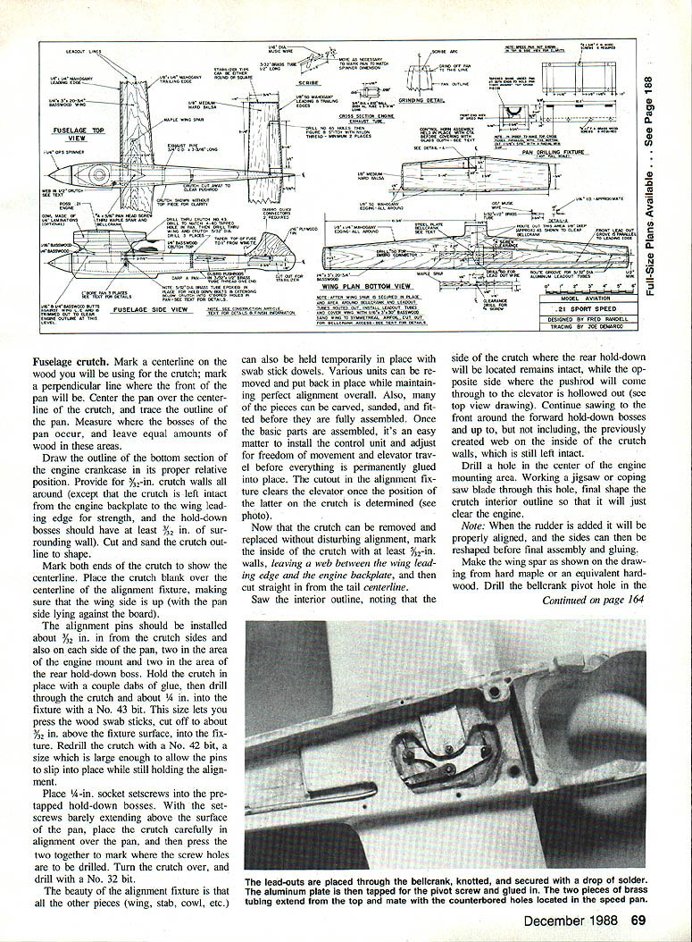
Make the wing spar as shown on the drawing from hard maple or an equivalent hardwood. Drill the bellcrank pivot hole in the approximate position shown on the plan.
Wing
Cut the wing to shape as shown in the plan, taking care to make the spar cutout a close fit. Glue the spar in place (Elmer's glue is recommended). Glue 3/16 x 1/4-in. mahogany strips in place as shown, holding with lots of masking tape until dry.
Groove or rout the wing for 3/32-in. lead-out tubing, then tack-glue the tubes in place. Make sure you have cleared away enough wood to provide for bellcrank travel. Position the bellcrank as shown, with the connector in place and a short length of pushrod installed. Install the pivot screw, and check for freedom of movement.
Using a 1/16 x 3 x 36-in. basswood sheet, make a cutout that will allow access to the bellcrank. Be sure that the cutout sheet is left solid at each tip. Glue it in place, trim it to outline, and carve it to a symmetrical airfoil section from root to tip. Do not carve the wing where it mounts on the crutch.
Note that the drawing shows this model set up for clockwise flying. Simply reverse the lead-out and spar positions in order to fly counterclockwise.
Stabilizer
Using 1/8-in. medium-hard balsa, build the stabilizer as per the drawing, and finish with 3/4-oz. glass cloth. Attach the stabilizer with epoxy, but do not paint it. Temporarily stitch the elevator in place, secure the elevator horn in position as shown, and adhere with epoxy.
Position the stabilizer on the centerline of the alignment fixture board as shown, then put two alignment pins through the stabilizer centerline and into the fixture centerline.
Add the Qwik Link with the pushrod attached. If you haven't already made the cutout to clear the elevator, do so now. Cut the pushrods to length.
Wing-to-crutch assembly
Align the wing on the crutch centerline, and tack-glue. Drill two holes (the locations are up to you) for the alignment pins. With the flying surfaces pinned in place, adjust the bellcrank-to-elevator travel as follows:
With the bellcrank in a neutral position and the elevator level, cut the butt ends of the pushrods so that they do not quite meet. Insert a piece of 3/32-in. x 1/2-in.-long brass tubing, and solder. Minor adjustments can now be made by disconnecting the pushrods from the elevator horn and turning the clip or nut. (Now you can see why we just pin everything in place at first.)
For final drilling for the brass sleeves in the crutch and wing use a 5/64 bit. The sleeves are epoxied in place through the wing and crutch, and then into the counterbored holes in the pan. Finish-drill the rear hold-down after the final top piece has been pinned in place for shaping, and then glue.
To build up the fuselage, cut out a piece of 1/4-in. basswood to fit around the engine and from the wing leading edge forward to the end of the crutch (pin this in two places). Add a piece of 1/16-in. basswood in the same manner to bring the top of the crutch even with the top of the wing. Fit a piece of 1/8-in. basswood between the wing trailing edge and the end of the crutch, cut a slot in it to fit around the rudder, and pin in place.
Final assembly
Cut the lead-outs to the desired length, tie a tight knot in one end, and secure with a drop of solder. Thread the lead-out cable through the holes in the bellcrank and out through the wing tip. Don't finish the ends yet, as you may want to pull the lines back inside the wing while you finish and paint.
Assemble the wing, crutch, and stab. With the assembly positioned on the alignment board, check all controls for freedom of movement and make certain there's clearance for horn and pushrod before gluing everything in place. Double-check that the wing fits properly, and glue.
Epoxy the 5/32-in.-dia. brass tubes through the wing and crutch into the counterbore in the pan, allowing some of the tubing to protrude above the wing. When this is dry, counterbore below the surface so that the hold-down screw fits flush. Repeat the procedure for the rear hold-down screw.
The 3/16-in.-long x 3/8-in.-dia. tubing is just pushed in place on the engine exhaust extension. If you cut the groove in the appropriate position shown in the drawing, no extra bolt-down screws are necessary to secure the tubing.
Engine cowling
The cowl is fashioned from a 1 3/4 x 1 1/2-in. block of medium-hard balsa. Determine the cylinder and exhaust centerline relative to the engine's position on the crutch. Place the block in a vertical position (check both orientations).
Drill a 1-in. hole for the exhaust, making sure you drill into the area where the cylinder will be located. Drill another hole about 1/2 in. larger than the cylinder diameter. Draw the cowl outline as you desire, and then saw to shape. Install the engine in the pan mount, and place the crutch at top. Position the cowl block as necessary to fit around the engine, and then pin the cowl to the crutch.
Note: If you use the option of tack-gluing a series of 1/4-in. laminations together and then splitting them apart after pre-boring the cylinder and exhaust holes, you can carve away the interior in steps to more closely match the engine shape.
With the cowl, crutch, and top pieces in place, but without the wing or stabilizer, the fuselage is ready to be carved and sanded to shape as per the drawing. Note that the configuration tapers from the wing trailing edge to where the rudder enters the crutch.
Covering and finishing
Sand all surfaces with No. 220 production paper until smooth. Cover the entire model, with the exception of the stabilizer, with 3/4-oz. glass cloth and adhere with K&B polyester resin. Cover small sections one at a time, overlapping the cloth as necessary. After the resin has fully cured, rough-sand the high spots to even the surface, and apply a second coat of resin.
When that's thoroughly cured, wet-sand the model with 220-grit wet-or-dry sandpaper. Apply two coats of ProFill (from Aero Craft Products, P.O. Box 62, Brenner Ave., N.W., Massillon, OH 44646; tel. 216-833-0789), wet-sanding after each application with 400-grit paper. Brush on Pactra Formula U for the final finish, and then stitch the elevator in place with nylon thread.
Your model is ready to be test flown and enjoyed. Hope your sojourn into the unique building methods of Control Line Speed has proven an interesting one. Return visits invited.
List of standard tools
- Dremel Moto Tool with assorted cutters and grinders
- Various numbered and fractional drills as indicated in the drawing
- Electric hand drill
- Coping saw, jigsaw, or band saw
- X‑Acto knife with various blades
- White glue, cyanoacrylate glue (CyA), and CyA debonder
- An assortment of wood files (whatever fits your hand)
- 4‑40 tap and No. 43 drill bit
Speed pan suppliers
- Nick Arpino, 301 Woodacres Rd., East Patchogue, NY 11772
- Des McAnelly, 47 Norwood St., Invercargill, New Zealand
- Herb’s Speed & Racing, 1621 M St., Merced, CA 95340
When responding to advertisers, mention that you read about them in Model Aviation.
Transcribed from original scans by AI. Minor OCR errors may remain.

