
3-Meter Scooter
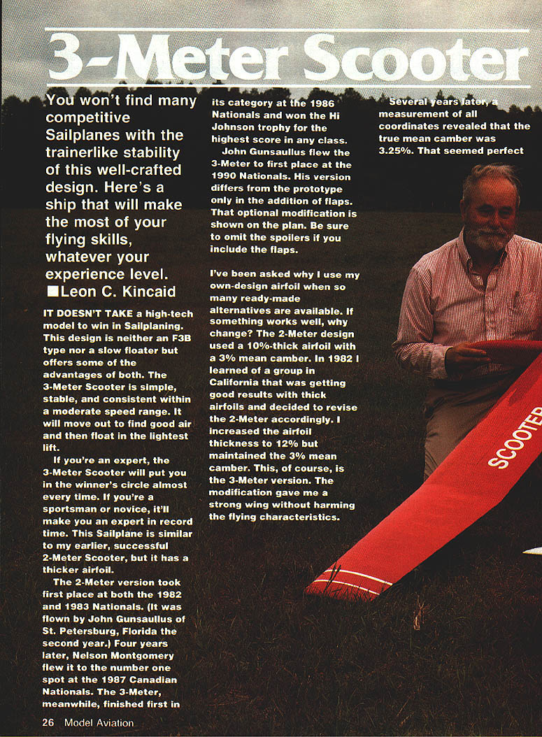
You won't find many competitive sailplanes with the trainer-like stability of this well-crafted design. Here's a ship that will make the most of your flying skills, whatever your experience level.
- Leon C. Kincaid
It doesn't take a high-tech model to win in sailplaning. This design is neither an F3B type nor a slow floater but offers some of the advantages of both. The 3-Meter Scooter is simple, stable, and consistent within a moderate speed range. It will move out to find good air and then float in the lightest lift.
If you're an expert, the 3-Meter Scooter will put you in the winner's circle almost every time. If you're a sportsman or novice, it'll make you an expert in record time. This sailplane is similar to my earlier, successful 2-Meter Scooter, but it has a thicker airfoil.
The 2-Meter version took first place at both the 1982 and 1983 Nationals (flown by John Gunsaullus of St. Petersburg, Florida in 1983). Four years later, Nelson Montgomery flew it to the number one spot at the 1987 Canadian Nationals. The 3-Meter finished first in its category at the 1986 Nationals and won the Hi Johnson trophy for the highest score in any class. John Gunsaullus flew the 3-Meter to first place at the 1990 Nationals; his version differs from the prototype only in the addition of flaps. That optional modification is shown on the plan. Be sure to omit the spoilers if you include the flaps.
I've been asked why I use my own-design airfoil when so many ready-made alternatives are available. If something works well, why change? The 2-Meter design used a 10%-thick airfoil with a 3% mean camber. In 1982 I learned of a group in California that was getting good results with thicker airfoils and decided to revise the 2-Meter accordingly. I increased the airfoil thickness to 12% but maintained the 3% mean camber. This, of course, is the 3-Meter version. The modification gave me a strong wing without harming the flying characteristics.
Several years later, measurement of all coordinates revealed that the true mean camber was 3.25%. That seemed perfect for my mission. Any airfoil with less than 3% mean camber belongs on a streamlined, high-performance sailplane. On the other hand, I didn't want a mean camber as high as 4%. At that level (and sometimes even at 3.5%) the model becomes more of a floater—and such ships often lose their ability to penetrate.
I experimented by removing one percent from the bottom of one prototype. This increased the mean camber one-half percent. The model flew extremely well, except that when I used down trim to move out faster, it responded more slowly than the thicker, lower-cambered plane.
Another experiment used computer-assisted design to reduce the airfoil to 10% while maintaining the same mean camber. Again, performance was terrific—in fact, hardly distinguishable from the 12%-thick-airfoil model—but for a single flaw: in trying to land, I found that the spoilers were almost worthless. The model needed flaps instead.
As noted, John Gunsaullus's success with a 3-Meter equipped with flaps prompted me to include flaps in the plan as an optional modification.
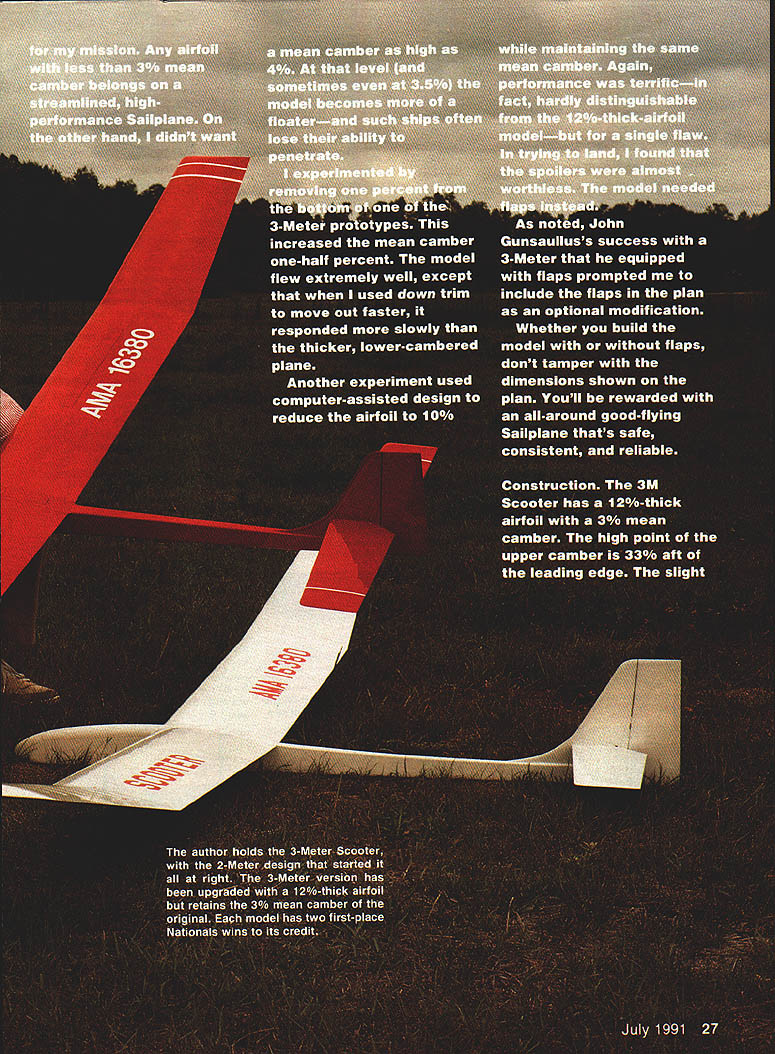
Whether you build the model with or without flaps, don't tamper with the dimensions shown on the plan. You'll be rewarded with an all-around good-flying sailplane that's safe, consistent, and reliable.
Full-size plans available, page 188.
Construction
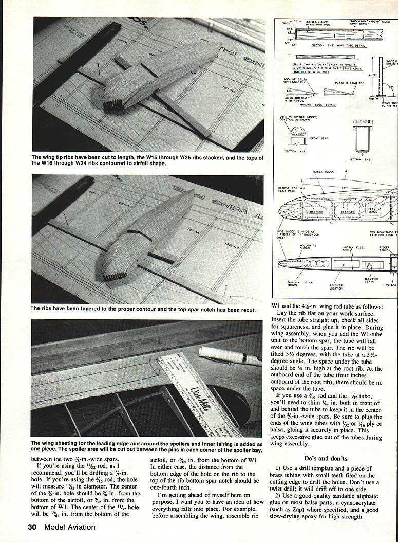
The 3-Meter Scooter has a 12%-thick airfoil with a 3% mean camber. The high point of the upper camber is 33% aft of the leading edge. The slight undercamber should cause no problems. Adding a 1/8-in. shim under the trailing edge keeps the bottom spar flat. With the rib in this position, the top spar will be 90 degrees above the bottom spar. From this point onward, the wing is built exactly as if it had a flat-bottomed airfoil.
The wing tip panel ribs are all cut out using the root rib (W1) as shown on the plan. While they maintain the same bottom contour as the root rib, their upper camber is different. This raises the trailing edge slightly and makes the chord line almost two degrees less at the tip than at the root. You get almost two degrees of aerodynamic washout right off the building board.
Obtaining the correct dihedral angle depends on proper drilling of the wing rod tube hole in the plywood root rib (W1). Until recently I used a Windsong 5/16 x 10-in. steel wing rod. Although this works extremely well, the newer Lovesong 3/8 x 10-in. rod is even better. The Lovesong rod requires a 3/8-in. O.D. brass tube in the wing; this fits perfectly when sandwiched between two 1/2-in.-wide spars.
Assemble rib W1 and the wing rod tube as follows: lay the rib flat on the work surface, insert the tube straight up, check that the sides are square, and glue it in place. During wing assembly, add the W1-tube unit before the bottom spar—the tube will tend to fall over and, if it touches the spar, the rib will be tilted about 3.5 degrees. The space under the tube should be 1/4 in. high at the root rib; at the outboard end of the tube (about four inches outboard of the root rib) there should be no space under the tube. If you use a 5/16-in. rod with a 3/32-in. tube you'll need a 1/64-in. shim both in front of and behind the tube to keep the center of the 1/2-in.-wide spars aligned. Be sure to plug the ends of the wing tubes with 1/16-in. ply or balsa, glued securely in place—this keeps excessive glue out of the tubes during wing assembly.
Make a 1/8-in. shim under the trailing edge during assembly and use Saran Wrap under the wing where the sheeting contacts the board.
Dos and don'ts
- Use a drill template or a piece of brass tubing with small teeth filed on the cutting edge to drill holes. Don't use a twist drill; it will drift off to the side.
- Use good-quality, sandable aliphatic glue for balsa parts. Cyanoacrylate (Zap) may be used where appropriate; for high-strength joints use a good slow-drying epoxy.
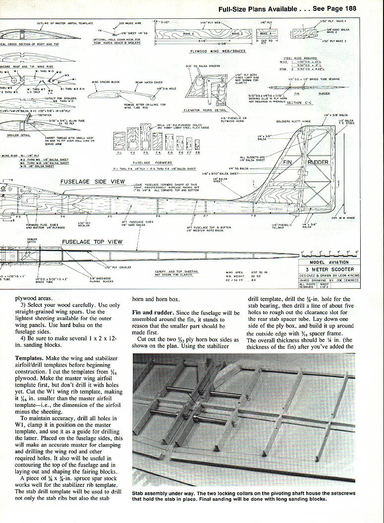
- Select your wood carefully. Use only straight-grained wing spars. Use the lightest sheeting available for the outer wing panels. Use hard balsa on the fuselage sides.
- Be sure to make several 1 x 2 x 12-in. sanding blocks.
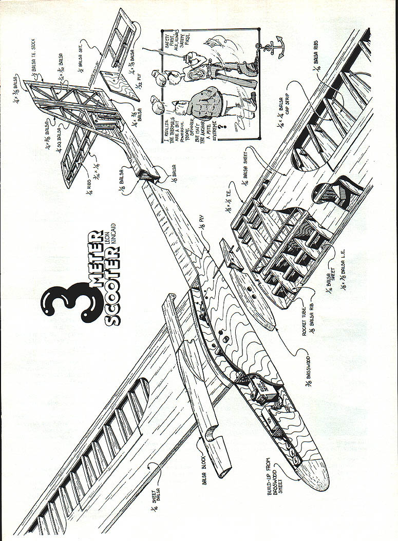
Build-up (parts and materials called out on plan)
- Build-up from 3/32 ply sheet
- Balsa block assemblies
- 1/8-in. sheet balsa pieces
- 1/8-in. ply parts
- 1/8-in. balsa ribs
- Rocket tube provisions (3/8-in. balsa rib area)
- 1/8-in. balsa cap strips
- 1/16-in. ply and 1/16-in. sheet where specified
- 1/8-in. leading edge cap between the two 3/8-in.-wide spars
Templates
Make the wing and stabilizer airfoil/drill templates before beginning construction. I cut the templates from 3/16-in. plywood. Make the master wing airfoil template first, but don't drill it with holes yet. Cut the W1 wing rib template, making it 1/16 in. smaller than the master airfoil template (i.e., the airfoil dimension minus the sheeting).
To maintain accuracy, drill all holes in W1, clamp it in position on the master template, and use it as a guide for drilling the master. Placed on the fuselage sides, this will make an accurate master for clamping and drilling the wing rod and other required holes. It will also be useful in contouring the top of the fuselage and in laying out and shaping the fairing blocks.
A piece of 1/8 x 3/8-in. spruce spar stock works well for the stabilizer rib template. The stab drill template will be used to drill not only the stab ribs but also the stab horn and horn box.
Fin and rudder
Since the fuselage will be assembled around the fin, make the fin/horn box first.
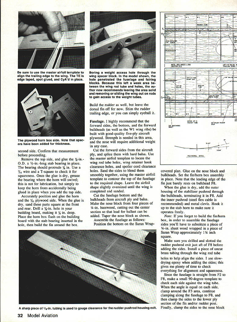
Cut out the two 1/2-ply horn box sides as shown on the plan. Using the stabilizer drill template, drill the 1/8-in. hole for the stab bearing, then drill a line of about five holes to rough out the clearance slot for the rear stab spacer tube. Lay down one side of the ply box and build it up around the outside edge with a 1/16-in. spacer frame. The overall thickness should be 1/4 in. (the thickness of the fin) after you've added the ply faces. Confirm this measurement before proceeding.
Remove the top side and glue the 1/8-in. O.D. x 1/2-in.-long stab bearing in place. The bearing should protrude 1/8 in. Use a 3/32-in. wire and a T-square to check it for squareness. Once the glue is dry, grease the bearing where the horn will swivel; this prevents the horn from accidentally being glued in place when you add the top side.
Accurately position and glue the horn and the 1/2-in. plywood side. When the glue is dry, sand these parts square at the front and rear. Drill a 1/8-in. hole in your building board, making it 1/8-in. deep. Place the horn box flush with the building board with the stab bearing inserted in the hole, then build the fin around the box.
Build the rudder as well, but leave the dorsal fin off for now. Shim the rudder trailing edge, or simply eyeball it for straightness.
Fuselage
I highly recommend that the forward sides, the bottom, and the forward bulkheads (as well as the W1 wing ribs) be built with good-quality five-ply aircraft plywood. Strength is needed in this area, and the nose will require additional weight in any case.
Cut the forward sides from aircraft ply and splice them with hard balsa. Use the master airfoil template to locate the wing rod tube holes, wing retainer hook clearance holes, and spoiler cord clearance holes. Sand the sides to blend them smoothly together, using the master airfoil template to contour the top of the fuselage to the required shape. Leave the airfoil shape slightly oversized until the wing is completed and sanded.
Cut the fuselage bottom and the bulkheads from aircraft ply and balsa. Make the nose block from four pieces of 1/4-in. basswood, cutting out the center section so that lead for ballast can be added. Taper the nose block as shown on the plan.
Assemble the fuselage as follows: position the bottom on the Saran Wrap-covered plan, glue on the nose block and bulkheads, and set the fin/horn box assembly in place. Note that the leading edge of the fin just barely rests on bulkhead F8. When dry, add the outer housing of the stabilizer pushrod through the bulkheads, terminating it in F8. Add the inner pushrod (steel flex cable recommended) and metal clevis. Hook it up to the stab horn to make sure it operates freely.
If you forget to build the fin/horn box, to assemble the fuselage sides you'll have to substitute a piece of 1/4-in. sheet wood wrapped in Saran Wrap about 1 1/4 in. square.
Make sure you drilled and slotted the rudder pushrod exit just aft of F8 before adding the sides. Install a piece of uncut brass tubing through the wing rod tube holes to help align the sides. I use slow-drying epoxy when adding the sides; this gives plenty of time to check alignment and squareness.
Since the fuselage is straight from F2 to F8, make a small 90-degree template to check each side against the wing tube. When the angle is equal on each side, clamp around the F3 area, continue clamping along the fuselage to F8, and then clamp the sides to the lower ply section of the fin and/or rudder post. Finally, clamp the sides to the nose block.
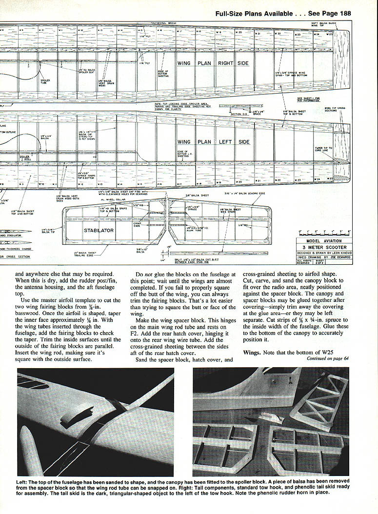
Use the master airfoil template to cut the two wing fairing blocks from 3/8-in. basswood. Once the airfoil is shaped, taper the inner face approximately 1/8 in. With the wing tubes inserted through the fuselage, add the fairing blocks to check the taper. Trim the inside surfaces until the outside faces of the fairing blocks are parallel. Insert the wing rod, making sure it's square with the outside surface.
Do not glue the fairing blocks to the fuselage yet; wait until the wings are almost completed. If you fail to properly square off the butt of the wing, you can always trim the fairing blocks—much easier than trying to square the butt of the wing later.
Make the wing spacer block. This hinges on the main wing rod tube and rests on F2. Add the rear hatch cover, hinging it onto the rear wing wire tube. Add the cross-grained sheeting between the sides aft of the rear hatch cover.
Sand the spacer block, hatch cover, and cross-grained sheeting to airfoil shape. Cut, carve, and sand the canopy block to fit over the radio area, neatly positioned against the radio block. The canopy and spacer blocks may be glued together after covering—simply trim away the covering at the glue area—or they may be left separate. Cut strips of 3/8 x 1/4-in. spruce to the inside width of the fuselage and glue these to the bottom of the canopy to accurately position it.
Wings
Note that the bottom of W25 matches the shape of W1. Consequently, all ribs can be cut using the W1 template. Make two ribs from 1/8-in. ply, ten from 1/16-in. ply, and 38 from 1/16- or 3/32-in. sheet balsa. Twenty of the 38 ribs will be used for the tapered tip panels—select ten for the left panel and ten for the right.
Using a thin-line felt-tip pen, mark two ribs as W16, two as W17, and so on through W25. Place one of the spars on the plan and insert each rib in its correct location. With the felt-tip pen, mark the ribs where excess is to be cut off at the leading and trailing edges.
Contour the top of the airfoil of the two W25 ribs as shown on the plan. Using a short piece of 1/8 x 3/8-in. spar stock, stack W15 through W25 and contour the tops of W16 through W24. Follow the same procedure for the opposite panel. Recut the top-spar notch in the tapered ribs as required.
Cut the leading and trailing edge sheeting to the proper length for each panel. Make the leading edge sheeting about 1/8 in. wider than shown on the drawing, since it contours over the ribs; trim the excess later.
Begin wing assembly by pinning the bottom leading edge sheeting in place on the plan. Position the bottom spar 1/8 in. from the edge of the sheeting, checking the distance with a straightedge. Secure the spars by holding or weighting them down, not by pinning, and glue them in place. CyA adhesives work well here.
Add the sheet trailing edge (do not pin it down) and remember to use a 1/8-in. shim under the trailing edge (and under the Saran Wrap) during assembly. Add ribs W6 through W14, then W16 through W25. Glue them to the spar area only, not to the leading or trailing edge sheeting.
Add the W1 plywood rib with the brass tubing. Tilt the rib until the tubing touches the bottom spar and add a drop of CyA to hold it in place.
Make a 3/8 x 3/4 x 6-5/8-in. spar spacer from two pieces of balsa (one 3/4 x 6-5/8 in., the other 1/4 x 3/8 x 6-5/8 in.). Attach the spacer to the bottom spar, flush against the end of the tube. You'll need it for spacing the spars where there are no ribs.
Add the main top spars in all panels and the 1/8 x 1/4-in. balsa spar for framing the spoiler in the center panels only. If you're using the optional flaps, omit the spoilers and their framing.
Add a 1/16-in. ply web/brace to one side of the tube area. Add tapered shims (primarily to fill up the space) and lots of epoxy to the area around the brass tube. Before the epoxy runs out, add the other 1/16-in. ply web/brace.
When the tube area is dry, cut and trim W2 through W5 and glue them in place. Add the remaining ply webs and the vertical-grained balsa webs. Plane and sand the leading edge; glue it to the ribs.
With a long straightedge or a piece of old trailing-edge stock, shim or wedge the leading edge sheeting against the ribs and CyA it in place. Go slowly, bending the sheeting as you work until all of it has been glued to the ribs and the leading edge. Leave the top sheeting off for now.
Because of the undercambered airfoil, only the tip of the ribs will touch the bottom sheeting at the trailing edge. With the trailing edge properly positioned but not pinned down, apply slight finger pressure to the top of each rib in turn until it bends and lies flat on the trailing edge. Add a drop of CyA, being careful not to glue your finger to the rib. When you release the finger pressure, the trailing edge will lift up with the rib—continue until all ribs are secured.
When the panels are dry, add the top trailing edge sheeting. Do not add the 1/2-in.-wide ply-and-balsa trailing edge at this time. Remove the panels from the building board and block-sand the ends at the polyhedral break until the panels fit together perfectly. Lay the center panel back on the board, prop the tip panel to the correct angle, and butt-glue the panels together. Wipe away excess glue.
When dry, add a 1/2-in.-wide brace between the spars and 1/32-in. ply braces to each side of the spar joint and the back side of the leading edge.
Add pasteboard rocket tubes (Estes BT-5) for additional ballast as shown on the plan.
Reposition and pin the center panel on the building board. Add the top leading edge sheeting. When this is completely dry, raise and shim the center panels until the outer or tip panels lie flat, and add the tip panel sheeting. Check for proper washout before all the pins have been added. Twist the tip if necessary until the trailing edge is about 1/8 in. higher at the tip than at the polyhedral break. When washout is correct, add the remaining pins.
Cut, trim, and sand excess sheeting from the leading edge. Add 1/8 x 3/4-in. hard balsa or spruce for the leading edge cap.
Add the inboard center panel fairing sheet to the bottom of the wing only. Add the diagonal-grained basswood block that anchors the wing retainer eye screws. Add a piece of balsa 1/2 in. square and approximately 1/8 in. long as a support, positioned between W1 and W2 above the 1/8-in. hole for the rear wing wire tube.
To insert the 1/8-in. O.D. brass wing wire tube into the wing at the proper angle:
- Remove the tubing from the fuselage.
- Install one wing half on the main wing rod. Using a long extension drill or a piece of 1/16-in. O.D. tubing with coarse teeth filed on the end, insert the tubing through the fuselage and one inside fairing block, then into the 1/8-in. hole in the W1 ply rib. Drill through the 1/8-in. support block until you’ve penetrated rib W2.
- Remove the first wing half and drill the opposite one. Add a little glue to a 1/8 x 2-1/4-in.-long tube, then insert it into the newly drilled holes. Crimp the end of the tubing to prevent the wire from entering too far.
Install the spoiler cord tubing (use rather stiff tubing). Add the top fairing sheeting and the cap strips. Temporarily install the spoilers, holding them in place with small hooks and rubber bands from within the spoiler bay.
Align the bottom of the 1/2-in.-wide ply-and-balsa trailing edge, ply side down, with the bottom of the wing. Tape the trailing edge temporarily in place and spot-glue with CyA. Check alignment; when correct, remove the tape and glue the trailing edge in place.
Add the lightweight balsa block wing tips. Make sure they are airfoil-shaped when viewed from the end. Taper the tips on the top and slightly on the bottom, continuing to the chord line. Round all corners and fair them in.
The completed wings are ready for trimming and sanding. Plane away all excess balsa from the tops of the trailing edge, spoilers, and leading edge. Sand all areas to final shape. I recommend making a female airfoil template and using it for at least the first third of the wing.
Stabilator
Build the stabilator relatively quickly; construct the two halves almost flat, then sand to final shape.
All ribs are 1/8 in. wide and the same length as the root rib. Cut four ribs from 1/8 x 3/16-in. spruce spar stock, and ten from 1/16- or 3/32-in. sheet balsa. Use the stabilator drill template to drill the ribs. Using two pieces of 1/8-in. O.D. tubing, stack each stab half and taper the ribs from 3/16 in. wide at the root to 1/8 in. wide at the tip. Leave the rib ends square for now. Notch the ribs for the 1/16 x 1/2-in. spars.
Place the bottom spar for each stabilator half over the plan, glue each rib to the spar, and cut away excess leading edge material. Add the slightly tapered 1/4-in. balsa webs/spacers between each rib. Ensure each spar cap is level with the spar notch, then add the top spar. Add leading and trailing edges and notch the trailing edge for the ribs.
Add tip blocks and gussets; gussets should be flush with the face of the spruce rib. I also add an aluminum wheel collar (Perfect brand), and drill and tap for a 4-40 allen-head setscrew. When dry, add a 1/8- or 3/16-in.-thick by 3/8-in.-wide spacer rib on the face of the root rib. Cut clearance holes in the spacer rib for the stab bearing and for the spacer tube in the horn box.
Trim the trailing edge for rudder clearance. Contour the leading edge with a razor plane and sanding blocks. Sand the ribs to fair in with the leading and trailing edge stock.
Covering
Good looks start with good sanding. Make full use of your sanding blocks and keep surfaces fair. A neat covering job does more for appearance than flashy trim; too much trim looks vulgar and adds drag.
For balancing and ballast, the wing can accept additional weight: slide the wings about an inch out on the wing rods and insert 1/2-in.-O.D., 1-in.-long slugs as required. If you need only half that much weight, insert six 1/2 x 1-in. pieces of wood dowel and then six slugs. Each wing panel can accommodate up to twelve 1-in.-long units. Lead is best but steel slugs or 1/2-in.-O.D. brass would also work.
Slow-floating sailplanes look beautiful aloft, but often they're unable to get out of bad air quickly enough. At the other extreme, models that attain very high speeds are at a disadvantage if they can't find super lift. The 3-Meter Scooter strikes a happy medium. Have fun with it while you're finding out for yourself.
Transcribed from original scans by AI. Minor OCR errors may remain.

