
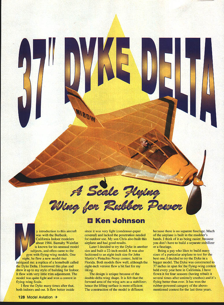
"37" Dyke Delta: A Scale Flying Wing for Rubber Power
Ken Johnson
My introduction to this aircraft was with the Burbank, California indoor modelers about 1984. Barnaby Wainfan is known for his unusual model subjects and often came to the gym with flying-wing models. One night he flew a new model that intrigued me: a replica of a homebuilt called the Dyke Delta. I borrowed this plan and drew it up to my style of building for indoor flying. It flew with very little trim adjustment, was quite light, and won a contest in flying-wing Scale.
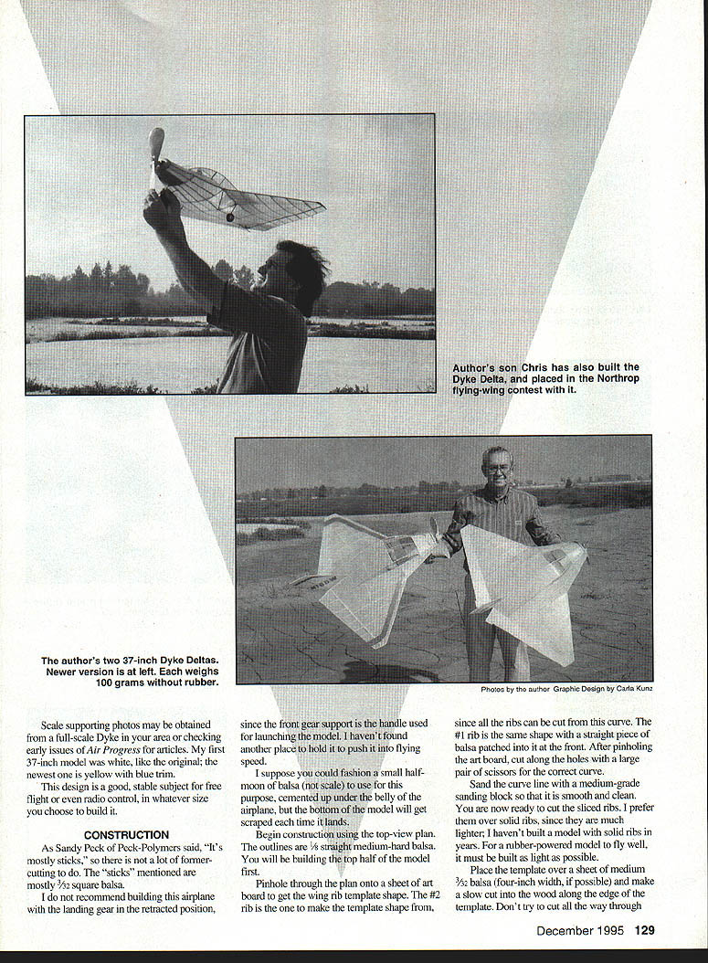
I flew the Dyke many times after that, both indoors and out. It flew better inside since it was very light (condenser paper covered) and lacked the penetration needed for outdoor use. My son Chris also built this airplane and had good results.
Later I decided to try the Dyke in other sizes and built a 22-inch model. It was also fashioned to an eight-inch size for John Martin's Pistachio Proxy contest held in Florida. Both models flew well, although the eight-inch version flew a bit fast for my liking.
The design is unique because of the double-delta wing shape. It is felt that the forward area of the wing acts as a stabilizer; hence the lifting surface is more efficient. The construction of the model is different because there is no separate fuselage—much of the airplane is built in the modeler's hands. I think of it as easier, because you don't have to build a separate stabilizer or a fuselage.
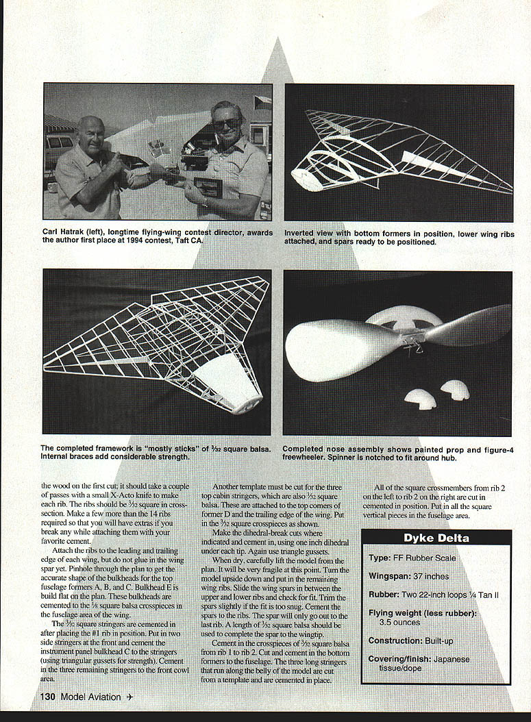
Being a builder who likes to make many sizes of a particular airplane to test for the best one, I decided to try the Dyke in a bigger model. The Dyke was constructed to 37 inches in span for the flying-wing contest held every year here in California. I have flown it for four seasons (having rebuilt it several times after untimely crashes) and it's flying better than ever. It has won the rubber-powered category of the above-mentioned contest for the last three years.
Scale supporting photos may be obtained from a full-scale Dyke in your area or by checking early issues of Air Progress for articles. My first 37-inch model was white, like the original; the newest one is yellow with blue trim.
This design is a good, stable subject for free flight or even radio control, in whatever size you choose to build it.
CONSTRUCTION
Materials and general notes
- Most construction is "sticks"—primarily 3/32" square balsa—so there is not a lot of former cutting to do.
- I do not recommend building the airplane with the landing gear in the retracted position, since the front gear support is the handle used for launching the model; I haven't found another place to hold it to push it up to flying speed.
- You could fashion a small half-moon of balsa (not scale) cemented under the belly for a launching hold, but the bottom of the model will be scraped each time it lands.
Begin construction using the top-view plan. The outlines are 1/8" straight medium-hard balsa. You will build the top half of the model first.
Ribs and templates
- Pinhole through the plan onto a sheet of art board to get the wing rib template shape. Use the #2 rib to make the template curve, since all the ribs can be cut from this curve. The #1 rib is the same shape with a straight piece of balsa patched into the front.
- After pinholing the art board, cut along the holes with a large pair of scissors for the correct curve. Sand the curve line with a medium-grade sanding block so it is smooth and clean.
- I prefer sliced ribs over solid ribs since they are much lighter. For rubber-powered models to fly well, they must be built as light as possible.
- Place the template over a sheet of medium 3/32" balsa (four-inch width, if possible) and make a slow cut into the wood along the template edge. Don't try to cut all the way through the wood on the first cut; it should take a couple of passes with a small X-Acto knife to make each rib. Ribs should be 3/32" square in cross-section. Make a few extras above the 14 required in case any break while attaching them.
Attach the ribs to the leading and trailing edges of each wing, but do not glue in the wing spar yet.
Bulkheads, stringers and fuselage formers
- Pinhole through the plan to get the accurate shapes of the top fuselage formers A, B, and C. Bulkhead E is built flat on the plan.
- Cement these bulkheads to the 3/32" square balsa crosspieces in the fuselage area of the wing.
- After placing the #1 rib, cement in the 3/32" square stringers. Put in two side stringers at the front and cement the instrument panel bulkhead C to the stringers (use triangular gussets for strength). Cement the three remaining stringers to the front cowl area.
- Cut a template for the three top cabin stringers (3/32" square balsa). Attach these to the top corners of former D and the wing trailing edge. Put in the 3/32" square crosspieces as shown on the plan.
Dihedral and spars
- Make the dihedral-break cuts where indicated and cement in, using a one-inch dihedral under each tip. Use triangle gussets at the dihedral joints.
- When dry, carefully lift the model from the plan—it will be fragile at this point. Turn the model upside down and put in the remaining wing ribs.
- Slide the wing spars in between the upper and lower ribs and check the fit. Trim spars slightly if the fit is too snug and then cement the spars to the ribs. The main spar will only go out to the last rib; use a length of 3/32" square balsa to complete the spar to the wingtip.
- Cement in the crosspieces of 3/32" square balsa from rib 1 to rib 2. Cut and cement the bottom formers to the fuselage. The three longer stringers that run along the belly are cut from a template and cemented in place.
- All square crossmembers from rib 2 on the left to rib 2 on the right are cut in and cemented. Put in all square vertical pieces in the fuselage area.
Control surfaces
- The elevons are built separately and attached before the model is covered. Cut and glue elevons to match the angle of the rear of the wing.
- A small length of 1/32" x 1/8" x 1/8" bamboo is cemented in vertically at the root of the wing on each side to represent the long hinge that sticks up out of each wing.
Dyke Delta (JD-2) — Specifications
- Type: FF Rubber Scale
- Wingspan: 37 inches
- Rubber: Two 22-inch loops of 1/4" Tan II
- Flying weight (less rubber): 3.5 ounces
- Construction: Built-up
- Covering/finish: Japanese tissue / dope
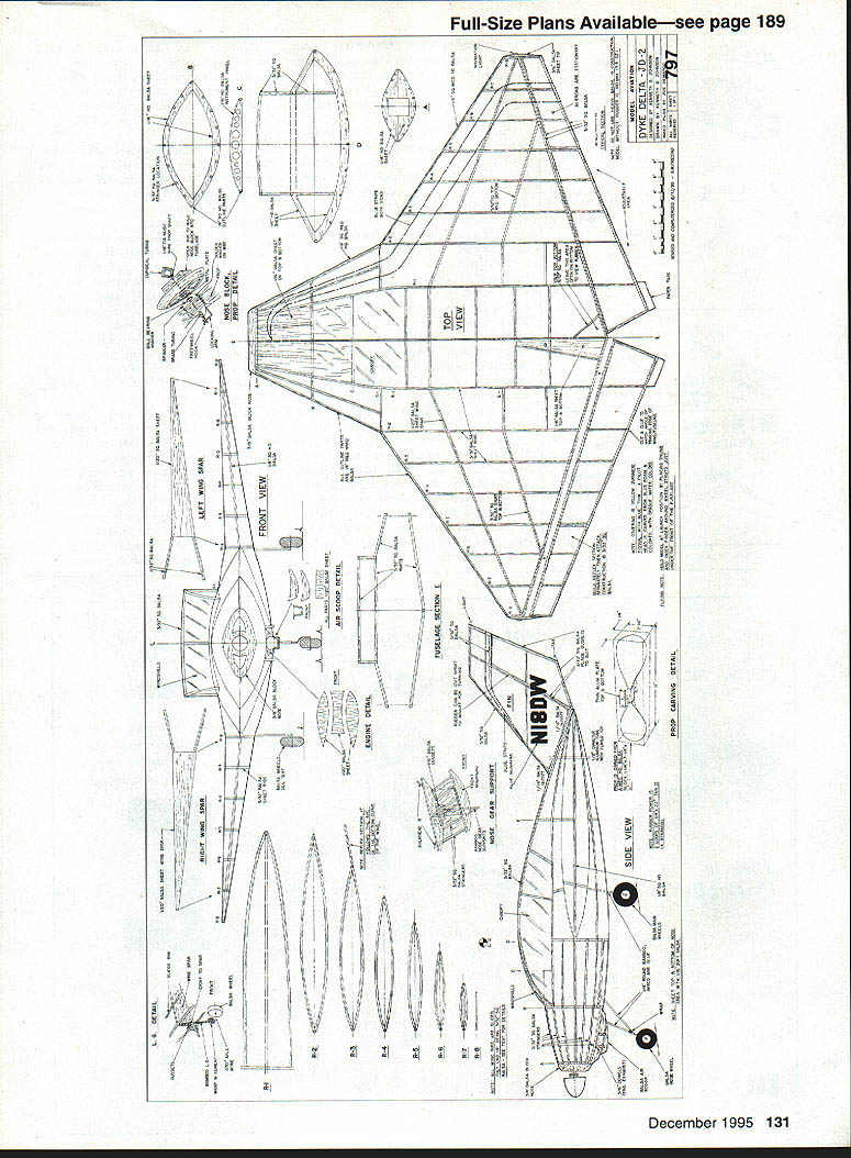
Plans / Diagram views and parts
- Top view
- Side view
- Front view
- Right wing
- Left wing spar
- R1, R2, R3, R4, R5, R6, R7, R8 (rib positions)
- Nose block
- Prop carving detail
- Air scoop detail
- Engine detail
- Nose gear support
- Fuselage section
- N1BDW
Applied Design Corporation PO Box 3384 Torrance, CA 90510
Nose reinforcement
It is necessary to strengthen the bottom area of the nose where the front wheel attaches. Cut a length of 3/32" x 1/2" and cement it to the inside of the center stringer. Put in triangle gussets and 3/32" square braces in this area.
Landing gear and supports
- For smaller rubber models heavy wire is unnecessary: the two main wheel struts on my model were 1/16" round bamboo (barbecue skewers from the supermarket work well).
- Use a small piece of .030" music wire bent to shape, wrapped, and cemented to the bamboo for each wheel axle.
- Cement the bamboo beam area to the wing spar with 5-minute epoxy.
- Note that the two rear landing gear supports are angled slightly forward at the bottom.
- The nose wheel support is made from the same bamboo and is angled toward the front of the model.
- The under-the-nose air scoop is 1/16" balsa. The exhaust pipes are 3/16" square balsa sanded round. Bend .030" music wire to shape and attach by wrapping with thread and cementing.
Wheels
- Balsa wheels are turned on a Dremel Moto-Tool. A standard corded Dremel (28,000 rpm) was too fast for wheels; a cordless Mini-Mite (5,000–10,000 rpm) worked much better. (Editor’s note: variable-speed Dremel tools are also available.)
- Draw small circles on card stock and cut out wheel hubs. Prespray the tire part with black auto primer. Paint the center paper discs to match model colors.
- Note the nose wheel is 1/4" smaller in diameter than the back wheels.
Finishing touches
- Many 3/32" square fuselage bracing sticks are internal—refer to construction photos to locate these. Remove crossmembers that are in the way of the rubber motor after the structure is built up.
- Install the instrument panel and cement it in position on the fuselage. Since the cabin area is flat plastic, a bubble canopy is not necessary.
- The wings fold across the top of the fuselage on the full-size Dyke so the aircraft can be made narrower for towing. The same hinges support each wing in the folded position.
COVERING AND FINISH
- My model is covered with yellow Japanese tissue. Trim stripes and numbers are blue Japanese tissue.
- Attach the windshield and side windows after covering. Color the windshield-area wood with a yellow marker before attaching the thin plastic windshield material.
- Flectite arrow cement (made to attach plastic vanes to aluminum arrow shafts—available from archery suppliers) works well to attach the windshield.
NOSEBLOCK AND PROPELLER
- The noseblock is cut from 3/8" sheet balsa. Hollow out the air scoops with a Dremel using a small round ball-end bit.
- Cement a 3/8" sheet block to the rear of the noseblock; add a small platform around the sides and top of the platform to ensure the noseblock does not fall out of the front of the model.
- Carve the propeller from a medium-hard balsa block measuring 1-1/2" x 2-1/2" x 1/4". After carving, sand and balance the prop, spray a coat of auto gray primer, sand lightly, then spray one coat of silver paint.
- Turn the balsa spinner on the Dremel using sandpaper. Notch the back of the spinner to pass over the prop hub, then slice it down the middle and cut a groove to accommodate the prop shaft. Cement the spinner over the prop hub, ensuring the shaft has free travel inside the spinner. The front of the spinner should come up to the end of the brass tubing.
FLYING
- Make a four-strand (two loops) rubber motor of 1/4" Tan II, about 22 inches long.
- The center of gravity should be about where the leading edge of the wing changes angle—approximately 8-1/4" from the rear of the noseblock.
- Put a few winds in the rubber and launch the model over tall grass. If it dives, lift the rear of the elevons slightly and cement. If it stalls, drop the elevons the same amount.
- When the model cruises in a straight line, add turns in the rubber until the model climbs nicely.
- Launch by holding around the front gear supports under the front of the fuselage. Launch directly into the wind or slightly to the right with the nose elevated slightly.
- A small amount of downthrust may be needed—perhaps a 1/32" to 1/16" shim behind the noseblock.
- Make sure your noseblock is a snug fit.
Good luck—I hope your Dyke flies as nicely as mine.
ACKNOWLEDGEMENTS AND CONTACT
This article is dedicated to Carl Hatrak, contest director for the flying wing contest held each year in California. 1995 was the 29th consecutive year Carl has directed this meet, and he has at times funded the trophies himself.
The contest was originally sponsored by Northrop Aviation, then publisher William Northrop, and now by the Southern California Ignition Flyers (SCIF). Proxy entries are accepted.
Ken Johnson 16728 Bermuda St. Granada Hills, CA 91344
Transcribed from original scans by AI. Minor OCR errors may remain.

