
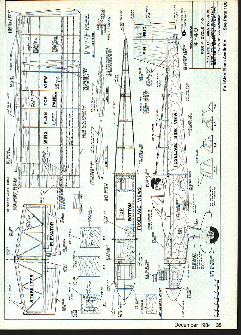
4-40
Dr. D. B. Mathews
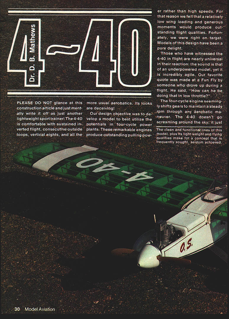
PLEASE DO NOT glance at this construction article and just mentally write it off as just another lightweight sport trainer! The 4-40 is comfortable with sustained inverted flight, consecutive outside loops, vertical eights, and all the more usual aerobatics. Its looks are deceiving!
Our design objective was to develop a model to best utilize the potentials in four-cycle powerplants. These remarkable engines produce outstanding pulling power rather than high speeds. For that reason we felt that a relatively low wing loading and generous moments would produce outstanding flight qualities. Fortunately, we were right on target. Models of this design have been a pure delight.
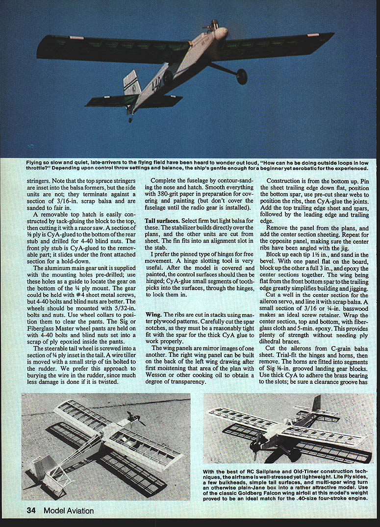
Those who have witnessed the 4-40 in flight are nearly universal in their reaction: the sound is that of an underpowered model, yet it is incredibly agile. Our favorite quote was made at a Fun Fly by someone who drove up during a flight. He said, "How can he be doing that in low throttle?" The four-cycle engine seemingly shifts gears to maintain a steady rpm through any aerobatic maneuver. The 4-40 doesn't go screaming around the sky; it just sort of chugs away in a delightful manner.
The clean and functional lines of this model, plus its light weight and flying qualities make for a concept that is frequently sought, seldom achieved. Have you gotten your feet wet yet with a plane powered by a four-stroke engine? Proponents have a lot of good things to say about them, not the least of which is the more pleasing sound of the engine. This plane is designed for a .40 four-stroke and four-channel controls. It's a docile flier yet amazingly aerobatic.
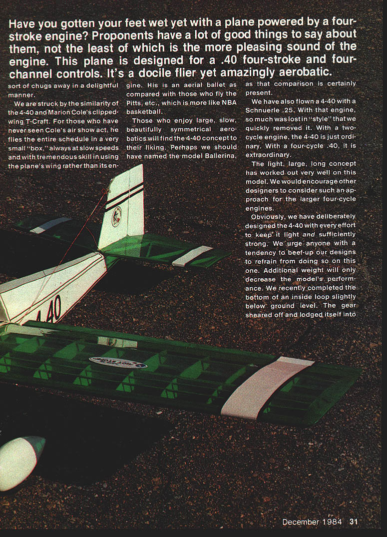
We are struck by the similarity of the 4-40 and Marion Cole's clipped-wing T-Craft. For those who have never seen Cole's air show act, he flies the entire schedule in a very small "box," always at slow speeds and with tremendous skill in using the plane's wing rather than its engine. His is an aerial ballet as compared with those who fly the Pitts, etc., which is more like NBA basketball.
Those who enjoy large, slow, beautifully symmetrical aerobatics will find the 4-40 concept to their liking. Perhaps we should have named the model Ballerina, as that comparison is certainly present.
We have also flown a 4-40 with a Schnuerle .25. With that engine, so much was lost in "style" that we quickly removed it. With a two-cycle engine, the 4-40 is just ordinary. With a four-cycle .40, it is extraordinary. The light, large, long concept has worked out very well on this model. We would encourage other designers to consider such an approach for the larger four-cycle engines.
At the risk of repeating ourselves, the 4-40 may look like a trainer, but it most certainly possesses qualities that will attract even the most jaded of pilots. This project has been one that seemed to be touched by some special magic from inception to completion. We are delighted to recommend it to you and all as something to really ENJOY.
Materials and Hardware
- Wood sizes are standard and available at hobby shops.
- Lite Ply (also known as poplar ply or door skins) is used for many parts; some building-supply stores carry it and Sig product is available through hobby shops.
- Landing gear and wheel pants can be ordered direct from Sig Mfg. Co.; they are replacement parts for Sig kits.
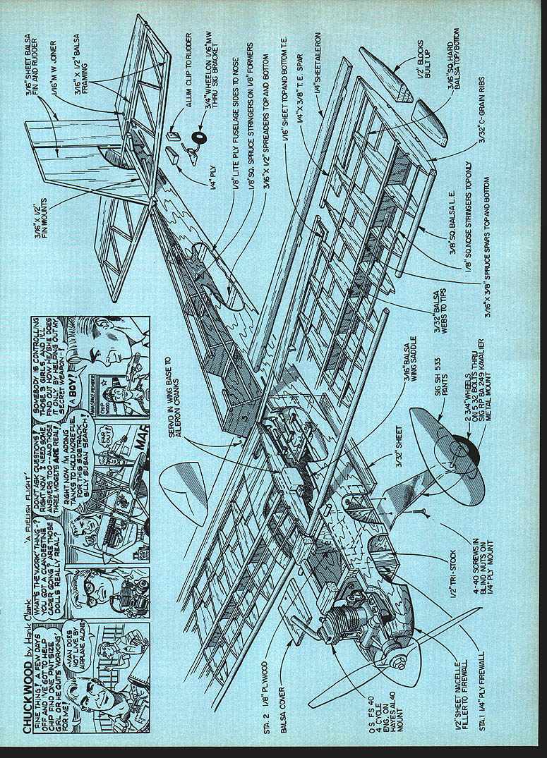
- Hayes AL-40 engine mount fits the O.S. .40FS perfectly; Saito and Enya four-strokes may require an alternate mount.
- Sig Fiberglass Master wheel pants recommended; use a scrap ply plate epoxied inside the pants for bearing.
- Use 4-40 bolts and blind nuts for gear and pants mounting; wheels mount on 5/32-in. bolts with wheel collars.
- Recommended glues:
- Thick cyanoacrylate (CyA) for most joints.
- 5-minute epoxy or 5-min. for fillets and higher-load joints.
- Heavier epoxy for firewall and critical wing joints.
Construction (General)
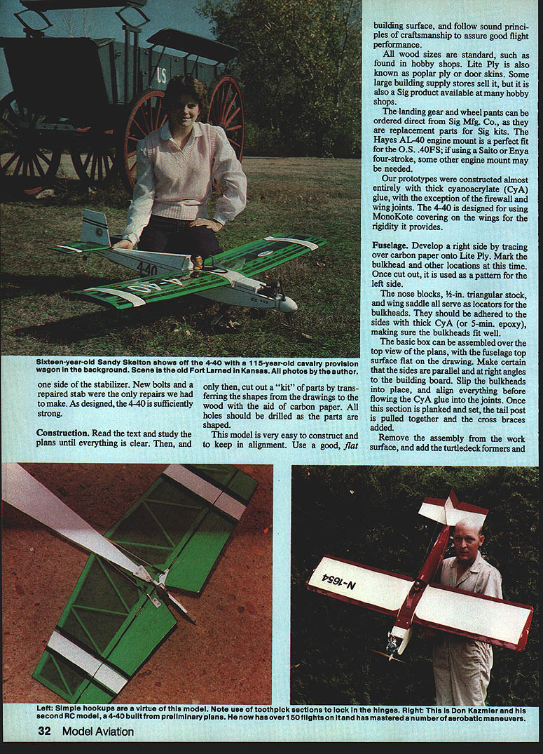
Read the text and study the plans until everything is clear. Cut out kit parts, transferring shapes from the drawings using carbon paper. Drill holes before parts are shaped. The model is very easy to construct if alignment is kept. Use a good, flat building surface and follow sound principles of craftsmanship to assure good flight performance.
Prototypes were constructed almost entirely with thick CyA glue, except for the firewall and wing joints where heavier adhesives are recommended. 4-40 is designed for MonoKote covering; the wing's internal rigidity and the plan-specified spars, ribs, and sheeting provide the required stiffness.
Note: the top spruce stringers are inset into the balsa formers; the side stringer units terminate against a section of 3/16-in. scrap balsa and are sanded fair.
Fuselage
- Develop the right side by tracing over carbon paper onto Lite Ply. Mark bulkhead and other locations at this time. Once cut out, use it as a pattern to make the left side.
- Adhere nose blocks, 1/2-in. or 3/8-in. triangular stock, and the wing saddle locators to the sides with thick CyA or 5-min. epoxy, making sure the bulkheads fit well.
- Assemble the basic box over the top-view plans with the fuselage top surface flat on the drawing. Ensure the sides are parallel and at right angles to the building board.
- Slip the bulkheads into place, align everything, then flow thick CyA into the joints. Once planked and set, pull the tail post together and add cross braces.
- Remove the assembly from the work surface, add turtledeck formers and planking, and contour-sand the nose and hatch. Smooth everything with 380-grit paper in preparation for covering and painting (but do not cover the fuselage until radio gear is installed).
Removable top hatch:
- Tack-glue a block to the top, cut a razor-saw section, and fit the hatch so it seats properly.
- Glue a bottom rear 1/8-in. ply stub and drill for 4-40 blind nuts.
- Glue a front ply stub to the removable part so it slides under the front attached section; use a hold-down as shown on the plans.
Landing gear and pants:
- The aluminum main gear unit is supplied with pre-drilled mounting holes—use them as a guide on the bottom of the 1/4 ply mount.
- #4 sheet-metal screws will hold the gear, but 4-40 bolts and blind nuts are preferred.
- Wheels should be mounted on 5/32-in. bolts and nuts; use wheel collars to position the wheels clear of the pants.
- Set a scrap ply plate epoxied inside the pants for the 4-40 bolts and blind nuts.
Tailwheel:
- The steerable tailwheel is screwed into a 1/4-in. ply inset in the tail.
- A small strip of tin bolted to the rudder moves the tiller; this approach avoids burying the rudder wire and reduces damage if the tiller is twisted.
Tail Surfaces
- Select firm but light balsa for stabilizer and elevator.
- Build the stabilizer directly over the plans; cut other units from sheet.
- The fin fits into an alignment slot in the stabilizer.
- Use pinned or slot hinges for free movement; a hinge-slotting tool is useful.
- After covering and painting, hinge the control surfaces and lock them by CyA-gluing small segments of toothpicks through the hinges.
Wing
- Ribs are cut in stacks using master plywood patterns.
- Carefully cut spar notches for a tight fit so thick CyA can form strong joints.
- The wing panels are mirror images. The right panel can be built on the back of the left wing drawing after moistening that area of the plan with Wesson or other cooking oil to obtain transparency.
- Construction is from the bottom up:
- Pin the sheet trailing edge down flat and position the bottom spar.
- Use pre-cut shear webs to position ribs, then CyA-glue the joints.
- Add the top trailing edge sheet, top spar(s), leading edge, and cap strips.
- Remove the panel from the plans and add center-section sheeting.
- Block up each tip 1/2 in. and sand in the bevel. When joining panels, block one panel 3 in. to set dihedral and epoxy the center sections together.
- The wing being flat from the front bottom spar to the trailing edge simplifies building and jigging.
Center section and servos:
- Cut a well in the center section for the aileron servo and line it with scrap balsa. A small section of 3/16-in. or 1/4-in. basswood makes an ideal servo mount.
- Wrap the center section, top and bottom, with fiberglass cloth and 5-min. epoxy to provide strength without ply dihedral braces.
Ailerons:
- Cut ailerons from C-grain balsa sheet.
- Trail-fit hinges and horns, then remove for final installation.
- Horns are fitted into segments of Sig 1/8-in. grooved landing gear blocks. Use thick CyA to adhere the brass bearing to the slots and cut a clearance groove in the center of the horn to clear the screw head.
- Use 5-min. epoxy to hold the block-horn unit to the trailing edge, then carve and sand the basswood to match.
- Carefully sand tip blocks to shape, then sand the entire wing in preparation for covering.
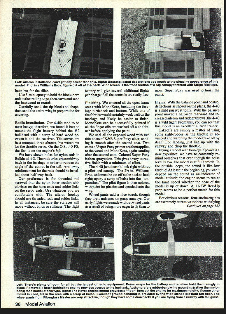
Radio Installation
- Our 4-40s tend to be nose-heavy; mount the flight battery behind Bulkhead #2 with a scrap of hardwood between it and the receiver.
- Servos are best mounted three abreast; check throttle servo location relative to the engine (on the O.S. .40 FS the throttle link is on the engine's left).
- Holes for nylon rods in Bulkhead #3 are shown on the plans. The rods criss-cross midway back in the fuselage to reduce the angle of the cutout in the tail. Install anti-sway reinforcement about halfway back.
- We prefer threaded rod screwed into the nylon inner section with clevises on the horn ends and solder links on the servo ends. Use whatever linkage you are comfortable with; the aileron hookup should use threaded rods and solder links.
- Ensure all surfaces move freely with no binds or stiffness. If controls are free, the flight battery will give several additional flights per charge.
Finishing
- Cover all open-frame areas with MonoKote, including the fuselage topdeck and bottom. MonoKote can be painted if finger oils are washed off with thinner before painting.
- Seal exposed wood with two thin coats of K&B Super Poxy clear, sanding smooth after the second coat.
- Apply two coats of Super Poxy primer, sanding after the second coat, then spray on colored Super Poxy for an attractive, durable finish.
- The 4-40 looks best with a pilot and canopy. The 2-1/2-in. Williams Bros. unit should be cut off at the neck to look right; epoxy a scrap of balsa into the neck area. Color the pilot figure with plastic paints and epoxy onto the wing.
- Wheel pants add a nice touch but can be a nuisance on grass runways. Super Poxy finishes the pants well.
Flying
- With the balance point and control deflections shown on the plans, the 4-40 is tame and easy to fly. Move the balance point a half-inch rearward and increase aileron and rudder throws for a much more aggressive machine.
- Takeoffs: apply some right-rudder as throttle is advanced and watch the model lift off on its own.
- Landings: line up with the runway and chop the throttle.
- Flying with a four-cycle engine is a new experience—sound is not always an indicator of power. The engine often seems to maintain the same rpm whether the nose is up or down. In outside loops the sound resembles low throttle even though the engine is at full power. An 11.5W Rev-Up prop is a near-perfect match for this model.
- Four-stroke engines are attractive to those with close flying-field neighbors because of reduced noise, lower fuel consumption, and their ability to turn large props.
Notes and Tips
- Use carbon paper to transfer shapes from drawings; drill holes before shaping parts.
- Thin CyA works well for most joints; reserve epoxy for high-stress areas.
- Wrap center section with fiberglass and epoxy for strength instead of ply dihedral braces.
- Use wheel collars to position wheels inside wheel pants.
- Be careful not to add unnecessary weight—this model was deliberately kept light and strong; added weight will reduce performance.
- The 4-40 is forgiving enough for beginners yet capable of precise, large-scale aerobatics for experienced pilots.
Enjoy building and flying the 4-40—it's a design that rewards craftsmanship and flies with a special grace that many four-stroke devotees will appreciate.
Transcribed from original scans by AI. Minor OCR errors may remain.

