
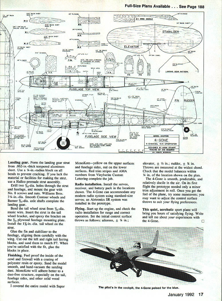
4-Gone
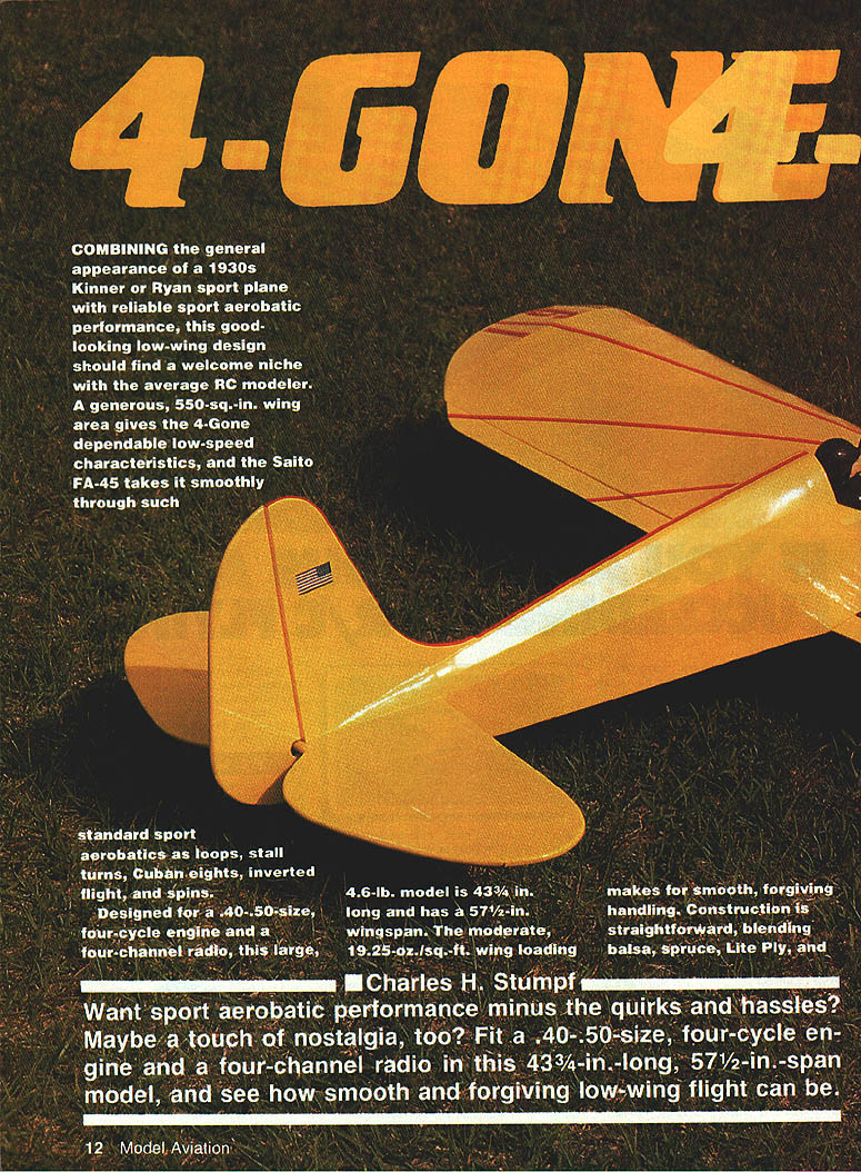
COMBINING the general appearance of a 1930s Kinner or Ryan sport plane with reliable sport aerobatic performance, this good-looking low-wing design should find a welcome niche with the average RC modeler. A generous 550 sq. in. wing area gives the 4-Gone dependable low-speed characteristics, and the Saito FA-45 takes it smoothly through such standard sport aerobatics as loops, stall turns, Cuban eights, inverted flight, and spins.
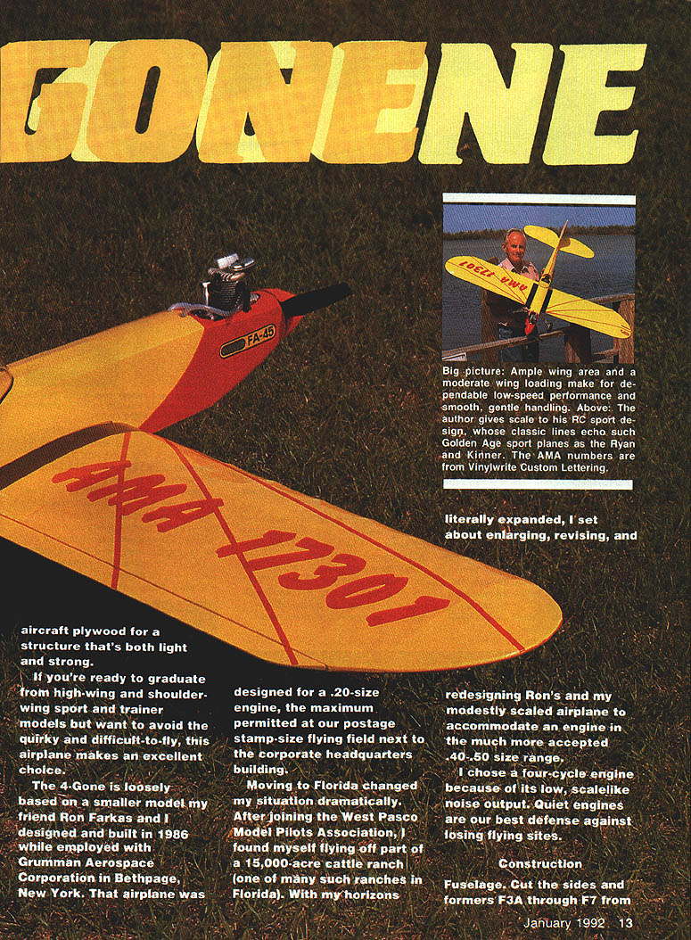
Designed for a .40–.50-size four-cycle engine and a four-channel radio, this large, 4.6-lb. model is 43-3/4 in. long and has a 57-1/2 in. wingspan. The moderate 19.25-oz./sq.-ft. wing loading makes for smooth, forgiving handling. Construction is straightforward, blending balsa, spruce, Lite Ply, and aircraft plywood for a structure that's both light and strong.
If you're ready to graduate from high-wing and shoulder-wing sport and trainer models but want to avoid the quirky and difficult-to-fly, this airplane makes an excellent choice.
The 4-Gone is loosely based on a smaller model my friend Ron Farkas and I designed and built in 1986 while employed with Grumman Aerospace Corporation in Bethpage, New York. That airplane was designed for a .20-size engine, the maximum permitted at our postage-stamp-size flying field next to the corporate headquarters building.
Moving to Florida changed my situation dramatically. After joining the West Pasco Model Pilots Association, I found myself flying off part of a 15,000-acre cattle ranch. With my horizons literally expanded, I set about enlarging, revising, and redesigning Ron's and my modestly scaled airplane to accommodate an engine in the more accepted .40–.50 size range.
I chose a four-cycle engine because of its low, scale-like noise output. Quiet engines are our best defense against losing flying sites.
Charles H. Stumpf
Specifications and performance highlights
- Wing area: 550 sq. in.
- Weight: approx. 4.6 lb.
- Length: 43-3/4 in.
- Wingspan: 57-1/2 in.
- Wing loading: 19.25 oz./sq.-ft.
- Recommended engine: .40–.50 four-cycle (Saito, Enya, O.S.)
- Prototype engine: Saito FA-45
- Typical flight duration: ~15 minutes (Du-Bro S-6, 6-oz tank)
- Radio: four-channel, standard-size servos
Construction
Fuselage
- Cut the fuselage sides and formers F3A through F7 from 1/8-in. aircraft plywood. Use 1/8-in. aircraft plywood for F1 and F3, and 3/16-in. aircraft plywood for F2.
- Cut the D-1 doublers from 1/8-in. aircraft plywood. Glue D1 and 3/8-in.-sq. upper and lower longerons to the fuselage sides, making a left and a right side.
- Drill holes in F2 for the engine mount and throttle pushrod. Install blind nuts for the engine mount.
- Mark former locations on both fuselage sides. Align the sides on a building board with a T-square, and glue F2, the three F3A's, and F4 in place. Allow glue to dry.
- Pull the sides together at the tail, check alignment, and glue. Glue in formers F5 through F7.
- Slot a 3/32-in. plywood tail-wheel mount plate for the tail-wheel bracket and install it per plan.
- Install the 1/4 x 7/8-in. balsa top stringer and 1/16-in.-sq. side stringers from F4 to F7. Install 1/4-in.-sq. spruce stringers from F2 to F4. Fill between the stringers from F2 to the first F3A former with 1/8-in. balsa sheet.
- Install Sullivan Gold-N-Clevis Nyrod tubes for the elevator and rudder pushrods and an additional Nyrod tube for the receiver antenna out the aft fuselage.
- Cover the fuselage bottom aft of the wing with cross-grained 3/32-in. sheet balsa.
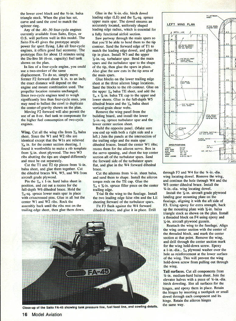
- Trial-fit the engine. Center-mount the F1 spinner ring on the engine shaft and glue in place. Remove the engine and add the lower cowl block of 1/2-in. balsa triangle stock; when the glue has set, carve and sand the cowl to match the spinner ring.
Notes on engine selection and installation:
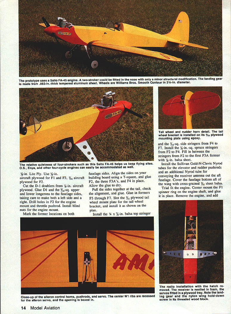
- Any .40–.50 four-cycle engine from Saito, Enya, or O.S. will perform well. The Saito FA-45 gives the prototype ample power and good fuel economy (about 15 minutes on the Du-Bro S-6 6-oz tank).
- If using a two-stroke of similar displacement, move former F2 forward about 3/4 in. to 1 in. (exact distance depends on engine/mount). Propeller location remains unchanged. Because two-stroke engines tend to weigh less, ballast may be needed to duplicate the plan CG. Moving F2 forward also permits using an 8-oz fuel tank to offset higher fuel consumption.
Wing
- Cut all wing ribs from 3/32-in. balsa sheet. W1 and W2 ribs are identical except W1 is relieved 1/16 in. for center-section sheeting—make a rib template from 1/8-in. sheet plywood. Cut the two W3 ribs (tip-adjacent) separately.
- Cut T1 and T2 tip pieces from 1/4-in. balsa sheet and glue them together. Cut dihedral braces W4, W5, and W6 from aircraft-grade plywood.
- Pin a 5/16-in.-sq. spruce lower main spar in place and cut the recess for the full-depth W6 dihedral brace. Hold the lower main spar with crisscrossed pins.
- Glue center W1 and W2 ribs in place. Rock the assembly back until ribs rest on the trailing-edge sheet and glue down.
- Glue a 1/4-in.-dia. birch dowel leading edge (LE) and a 5/16-in.-sq. spruce upper main spar. The dowel ensures an accurately located, uniformly shaped leading-edge radius essential for the airfoil section.
- Saw partway through the main spars so they can be bent to the tip contour. Sand the forward edge of T1 to match the leading-edge dowel and glue the tip in place.
- Install the W3 ribs and the upper 1/8-in.-sq. turbulator spar. Bend the main spars and turbulator spar to shape at the tip and glue in place. Also glue up the saw cuts in the tip area of the main spars.
- Glue blocks to the lower trailing-edge sheet at the three aileron-hinge locations and sand them to rib contour. Glue the upper 1/16-in. balsa TE sheet and add a 3/32-in. balsa TE cap to the upper and lower sheets (or a 1/16 x 3/8-in. balsa TE cap where specified).
- Glue in the full-depth W5 dihedral brace and 1/16-in. vertical-grain shear webs.
- Remove the wing panel from the board and install the lower 1/8-in.-sq. spruce turbulator spar and the lower center-section sheet.
- Build the opposite panel (ensure a left and a right). Join the panels at the trailing edge/main-spar intersection with the dihedral braces. Install the center W1 ribs; recess them for the aileron servo. Box in the servo opening and sheet the top center section aft of the turbulator spars.
- Sand forward side of turbulator spars flat and glue in the W4 forward dihedral brace.
- Cut ailerons from 1/4-in. sheet balsa and sand to shape. Install aileron torque rods on the TE cap. Glue a 1/16 x 3/8-in. spruce filler piece on the center trailing edge.
- Trial-fit the wing to the fuselage. Install the two leading-edge false ribs and the LE sheeting forward of the turbulator spars.
- Fit F3 flush against the W4 forward dihedral brace and glue in place. Drill through F3 and W4 for the 1/4-in.-dia. wing locating dowel. Remove the wing and continue the hole through W4 and the W5 center dihedral brace. Install the 1/4-in. wing-locating dowel.
- Install a 1-in.-dia., 1/16-in. plywood washer epoxied over the wing hold-down screw hole on the lower wing surface to prevent pull-through.
Tail surfaces
- Cut all fin, rudder, stabilizer, and elevator components from 1/8-in. medium-hard balsa sheet.
- Join elevator halves with a 1/4-in.-dia. birch dowel. Slot all surfaces for the hinges and epoxy them in place.
- Retain hinges by inserting a toothpick or small dowel through each hinge and surface; do the same for the aileron hinges.
- Glue the fin and stabilizer to the fuselage, aligning carefully with the wing. Cut left and right tail-fairing blocks, sand to match F7, and glue in place when fit is satisfactory.
Landing gear
- Form the landing-gear strut from .062-in.-thick tempered aluminum sheet. Use a 1/4-in.-radius block on all bends to prevent cracking. If you lack material or facilities, use a Hallco premade strut assembly.
- Drill two 5/32-in.-dia. holes through the strut and fuselage, and mount the gear with No. 8 screws and nuts. Use a 1/4-in. aircraft-grade plywood landing gear mounting plate on the fuselage, aligning it with the aft side of F3. Back up the mounting plate with 3/16-in. balsa triangle stock and epoxy for extra strength.
- Install a threaded block on F4 using epoxy and 1/8-in. aircraft plywood gussets.
- Bend the tail-wheel strut from 3/32-in.-dia. music wire. Insert the strut in the tail-wheel bracket and epoxy the bracket on the 1/32-in. plywood fuselage mounting plate. Install a 1-3/8-in.-dia. tail wheel on the strut.
- Wheels and axles: Williams Bros. 3-1/4-in.-dia. Smooth Contour wheels and Banner 5/8-in.-dia. axle shafts were used on the prototype.
Finishing
- Fuel-proof the inside of the cowl and firewall with a coating of polyester resin or epoxy.
- Sand the model smooth and hand-vacuum the sanding dust; MonoKote adheres better to a dust-free structure, especially on tail, fuselage sides, and other solid wood surfaces.
- Covering used on the prototype: Super MonoKote yellow on upper surfaces and fuselage sides; red on lower surfaces. Add red trim stripes and AMA numbers (the prototype used Vinylwrite Custom Lettering).
Radio installation
Install servos, receiver, and battery pack in the locations shown on the plan. The 4-Gone can accommodate any modern radio system using standard-size servos; an Airtronics RS system was installed in the prototype.
Flying
- Start the engine and check the radio installation for range and correct operation.
- Set initial control surface throws (measured at the widest chord):
- Ailerons: ±1/4 in.
- Elevator: ±1/2 in.
- Rudder: ±3/4 in.
- Check that the model balances within 1/4 in. of the location shown on the plan.
- The 4-Gone is smooth, predictable, and relatively docile in the air. The prototype needed only a minor trim adjustment in roll on its first flight. Once you get the feel of the plane, try maneuvers and adjust control throws to suit your flying preferences.
This quiet, aerobatic sport plane will bring you hours of satisfying flying. Write and tell me about your experiences with the 4-Gone.
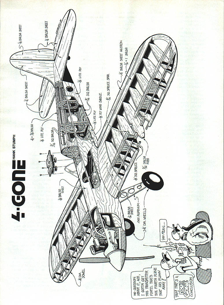
(The assembly drawing included part callouts:)
- 1/8 BALSA SHEET
- 1/4 BALSA SHEET
- 1/8 LITE PLY
- 1/8 SQ. BALSA
- 1/16 BALSA SHEET — AILERON
- 5/16-SQ. SPRUCE SPAR
- 1/4 DIA. DOWEL
- 1/8 PLY
- 0.032 ALUMINUM
- 3-1/4 DIA. WHEELS
Transcribed from original scans by AI. Minor OCR errors may remain.

