
47/88 RC Special
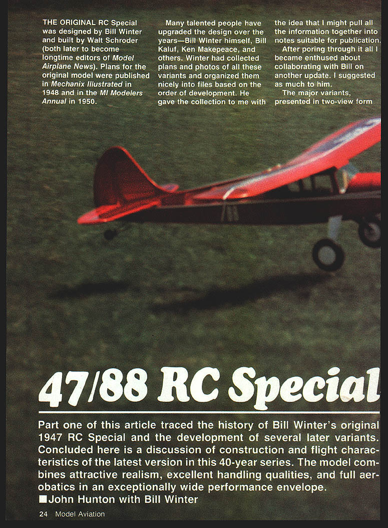
The original RC Special was designed by Bill Winter and built by Walt Schroder (both later to become longtime editors of Model Airplane News). Plans for the original model were published in Mechanix Illustrated in 1948 and in the MI Modelers Annual in 1950.
Many talented people have upgraded the design over the years—Bill Winter himself, Bill Kaluf, Ken Makepeace, and others. Winter collected plans and photos of these variants and organized them into files based on the order of development. He gave the collection to the author with the idea that it might be pulled together into notes suitable for publication. After poring through it all, the author became enthused about collaborating with Bill on another update.
Part one of this article traced the history of Bill Winter's original 1947 RC Special and the development of several later variants. Concluded here is a discussion of construction and flight characteristics of the latest version in this 40-year series. The model combines attractive realism, excellent handling qualities, and full aerobatics in an exceptionally wide performance envelope.
Last month's coverage of the history included Winter's three-channel scaled-down design (published in the September 1980 MA) and Bill Kaluf's five-channel flapped version (published in Australia's Airborne magazine). Kaluf's model is on display in the AMA Museum. Ken Makepeace's further modification of that version was capable of doing rolling 360s even with the flat-bottomed airfoil.
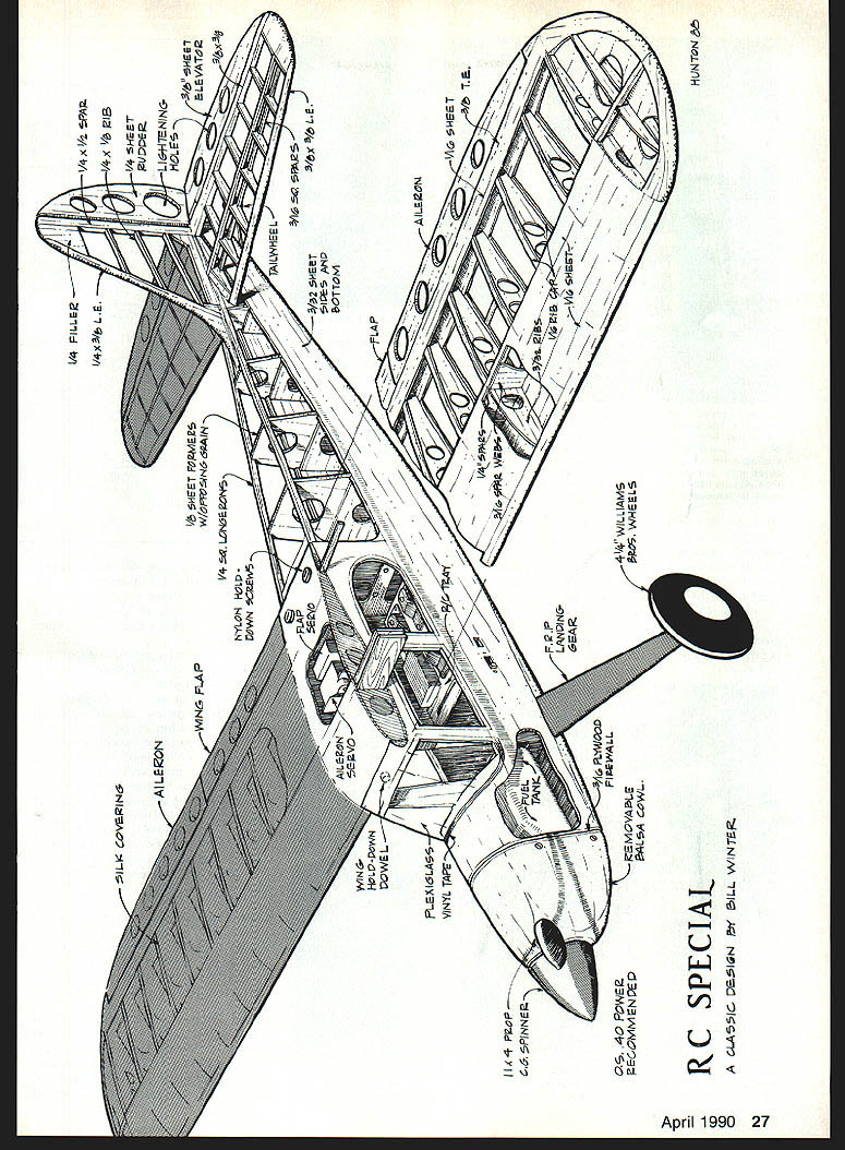
The new 1988 version includes so many modifications that it borders on a complete redesign. It features increased wing area, a semisymmetrical airfoil, and thinner, cleaner lines. The end result was to take the 42-year-old basic design into its first intentionally aerobatic version. It's significant to note that Winter originally had an Astro .40 electric motor in mind for power.
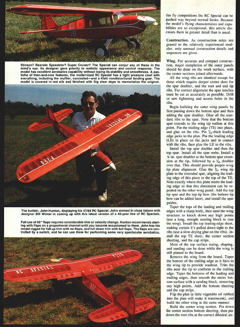
Because the design blends various historic antecedents, it manages to evoke different aircraft to different people. Some see the Piper Cub; others are reminded of the Aeronca, Rearwin, or Interstate.
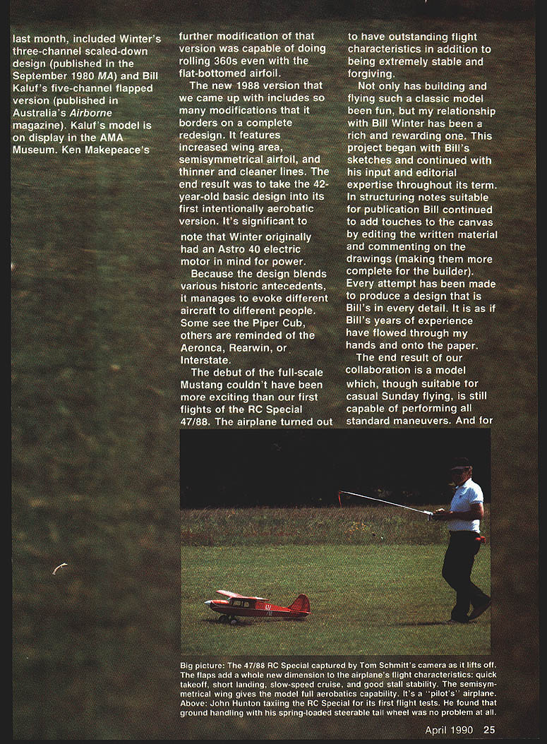
The debut of the full-scale Mustang couldn't have been more exciting than the first flights of the RC Special 47/88. The airplane turned out to have outstanding flight characteristics in addition to being extremely stable and forgiving.
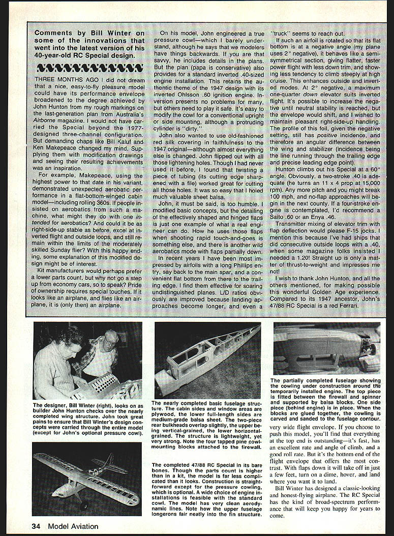
Working with Bill Winter was a rich and rewarding experience. The project began with Bill's sketches and continued with his input and editorial expertise throughout. In structuring notes suitable for publication Bill added touches by editing the written material and commenting on the drawings to make them more complete for the builder. Every attempt was made to produce a design that is Bill's in every detail. The end result of the collaboration is a model which, though suitable for casual Sunday flying, is still capable of performing all standard maneuvers. For fun-fly competitions the RC Special can be pushed well beyond normal limits. Because the model's flying characteristics and capabilities are so exceptional, these notes discuss them in greater detail than is usual.
Construction
As the construction notes are geared to the relatively experienced modeler, only unusual construction details and sequences are given.
Wing
Accurate, compact construction is a major point. Major completion of the outer panels should be done on the work surface, with the center section joined afterwards. All wing ribs are identical except for those that require deeper center slots for the spar doubler, and the root-end and tip ribs. For correct alignment the spar notches must be cut as accurately as possible. Drill or saw lightening and access holes in the ribs.
Begin building the outer wing panels by first pinning down the bottom spar and then adding the spar doubler. Glue all the standard ribs to the spar. Note that the bottom spar extends to the wing tip outline at this point. Pin the trailing edge (TE) into place and glue on the ribs. Pin 3/16-in. leading-edge jacks to the plan. Pin the leading edge (LE) in place on the jacks and in contact with the ribs, then glue the LE to the ribs.
Install the top spar doubler and then the top spar. Install all the spar webs. Install a 1/4-in. spar doubler at the bottom-spar extension at the tip, followed by a 1/16-in. doubler over that. This provides proper wing tip plate alignment. Glue the 3/32-in. wing tip plate to the extended spar, aligning the trailing edge of this piece to the top of the TE. Note exactly where this plate meets the leading edge so that this dimension can be repeated on the other wing panel. Add the top tip spar and the top tip bow (the bottom tip bow can be added later), and install the spar guides.
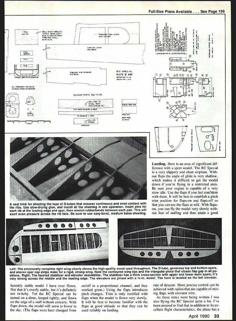
Taper the tops of the leading and trailing edges with a sharp knife, then sand the wing structure to knock down any high points (use a long, straight sanding block to true the wing). Install the top leading-edge sheet, making certain it's pulled down tight to the ribs; use slow-drying glue on the ribs. Install the top TE sheet, the center-section sheeting, and the cap strips.
Most of the top-surface truing, shaping, and sanding can be done while the wing is still pinned to the board. Remove the wing from the board. Taper the bottom of the trailing edge as it fairs to the wing tip to provide washout. Trim the ribs near the tip to conform to the trailing edge. Taper the bottoms of the leading and trailing edges, then smooth the entire bottom surface with a sanding block, removing any high points. Add the bottom sheeting and the cap strips.
Flip the plan (a little vegetable oil rubbed into the plan will make it translucent), and build the other wing in the same manner.
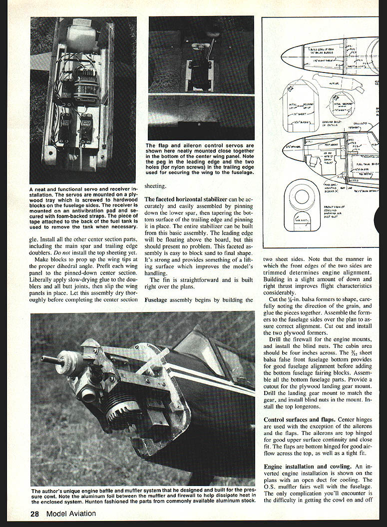
Build the center wing section by pinning down the center-section bottom sheeting and the root ribs at the correct dihedral angle. Install other center-section parts including the main spar and trailing-edge doublers, and install the top sheeting. Make blocks to prop up the wing tips at the proper dihedral angle. Prefit the wing panels to the pinned-down center section. Liberally apply slow-drying glue to the doublers and butt joints; slip the wing panels in place. Let the assembly dry thoroughly before completing the center-section sheeting.
Stabilizer and elevators
The faceted horizontal stabilizer can be accurately and easily assembled by pinning down the lower spar and tapering the bottom surface. Pin the trailing edge in place; the entire stabilizer can be built as a basic assembly. The leading edge will be floating above the board and should present no problem. The faceted assembly is easy to block-sand to final shape. It's strong, provides a smooth lifting surface, and improves the model's handling. The elevators are joined with a 1/4-in. dowel. The horn is located on the left elevator.
Fin
The fin is straightforward and is built right over the plans.
Fuselage
Begin by building the two sheet sides. Note that the manner in which the front edges of the two sides are trimmed determines engine alignment. Building in a slight amount of down and right thrust improves flight characteristics considerably.
Cut the 3/16-in. balsa formers to shape, carefully noting the direction of the grain, and glue the pieces together. Assemble the formers to the fuselage sides over the plan to ensure correct alignment. Cut out and install the two plywood formers.
Drill the firewall for the engine mounts and install blind nuts. The cabin area should be four inches across. The 3/8-in. balsa fuselage bottom provides good fuselage alignment before adding the bottom fuselage fairing blocks. Assemble all the bottom fuselage parts. Provide a cutout for the plywood landing-gear mount. Drill the landing-gear mount to match the gear and install blind nuts in the mount. Install the top longerons.
Control surfaces and flaps
Center hinges are used with the exception of the ailerons and the flaps. The ailerons are top-hinged for good upper-surface continuity and close fit. The flaps are bottom-hinged for good airflow across the top as well as a tight fit. The prototype later changed the flaps from on/off to a proportional channel, which worked well. Using the flaps introduces pitch changes; establish a pitch-trim position for flaps-on and flaps-off so the flaps can be used reliably on landing. Mixing flap deflection with elevator trim on the transmitter is useful.
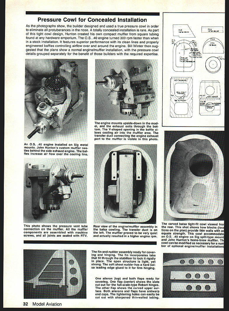
Engine installation and cowling
An inverted engine installation is shown on the plans with an open duct for cooling. The O.S. muffler fits well with the fuselage. The only complication is getting the cowl on and off around the muffler and needle valve.
- For the needle valve you'll need a deep socket to fit the needle-valve hex (or modify it as a two-flat version). This tool can be notched with a Carborundum wheel on a Dremel tool to clear the needle-valve spring so the needle valve can be easily removed to facilitate cowl removal.
- For the muffler, either provide access holes for muffler removal or notch out the cowl to the rear so that it will slip over the muffler extension.
Pressure cowl alternative
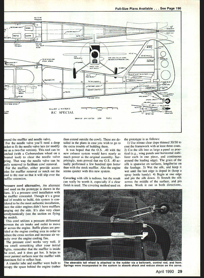
An alternate cowl used on the prototype is shown in the plans. It's a pressure-cowl installation with the muffler concealed. Though it's more trouble to build, this system is considered the most authentic installation, since older engines didn't have mufflers hanging out the side. It's also very clean aerodynamically.
This cowl utilizes a pressure differential between the air intake and outlet to move air across the engine. Baffle plates are provided at the engine cooling area to reduce the cross section and increase air velocity over the engine cooling fins.
The pressure cowl works very well. If you smell something after initial flights, remember that the muffler is inside the cowl and it gets hot—cover painted surfaces near the muffler with aluminum foil to reflect heat.
A transfer tube and muffler were built to occupy the space behind the engine rather than extend outside the cowl; these are detailed in the plans if you wish to build them. Tests showed an O.S. .40 with the new exhaust system ran a few hundred rpm better than with the stock muffler and seemed quieter.
Covering (silk)
Covering with silk is tedious but rewarding, especially with a clear finish. The covering method used on the prototype:
- Use nitrate dope or dope thinned 50/50 to coat the framework with at least three coats.
- Cut the silk into as large a panel as practical (e.g., wing panels and horizontal stabilizer each in one piece, and continuous around the leading edge). The grain of the silk is spanwise on surfaces and lengthwise on the fuselage.
- Wet the silk and keep it wet until the last edge is doped in (keep a spray bottle handy).
- Begin at one edge and press the silk down.
- Stretch the silk across the middle of the surface and pin it down. Work it out in both directions.
- Continue stretching and pinning down as you go until the entire panel is in place.
- Each time you get an edge pinned and tight, dope it down.
- Overlap edges by stretching the silk with your fingers.
- Use very thin clear nitrate for the first coats until the silk is sealed (suggestion: dope the surface upside down).
- After sealing the silk with nitrate and allowing it to set completely, switch to butyrate clear dope (nitrate isn't fuel-proof) for the final three coats or so.
When doping, the use of a retarder can prevent blushing in humid conditions. Fine-grain silk is available from Model Covering Co., 2320 Ocean Parkway, Brooklyn, NY 11223.
Flying
The 47/88 proved to be one of the most interesting models to fly—stable yet capable of crisp aerobatics. The following notes and the maiden-flight account should prepare you for what to expect.
Maiden flight summary (John Hunton, September 1988):
"The Special taxied straight ahead, being very responsive to the rudder, and left the ground of its own accord after a rather short takeoff run. I lifted the nose in a fairly steep climb attitude to get some altitude safely under the model. It was readily apparent that the new Special had a high rate of climb and was — literally — in its element."
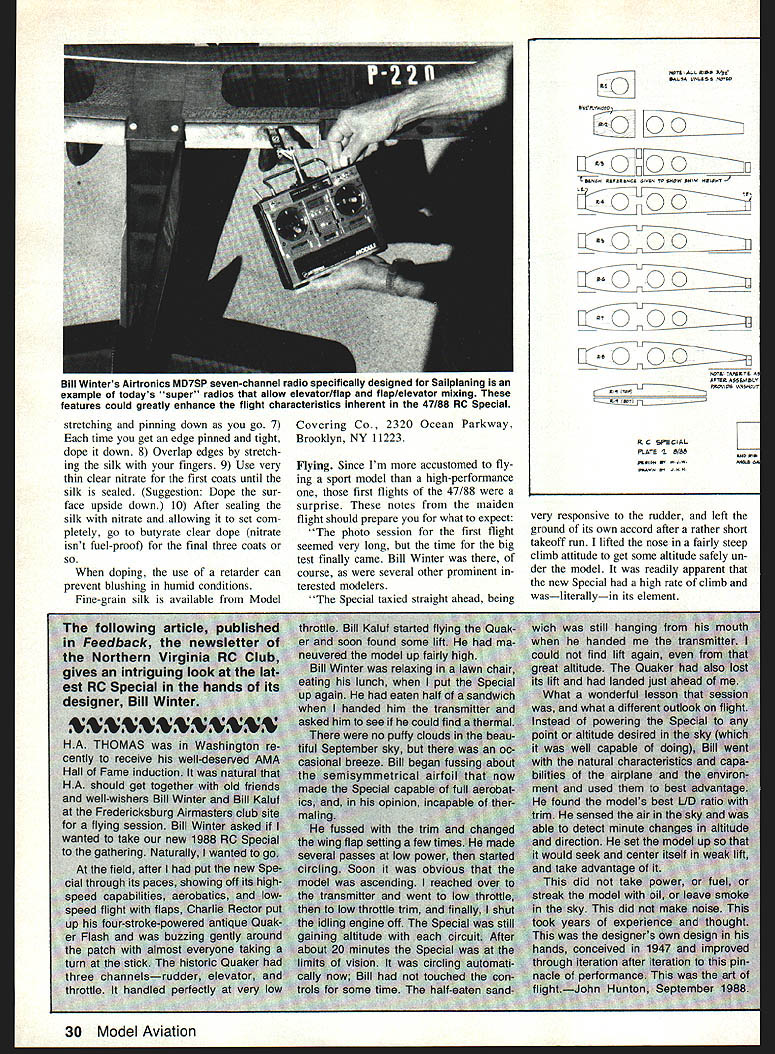
Bill Kaluf started flying another model and found lift. Bill Winter, relaxing in a lawn chair eating his lunch, took the transmitter for the Special. He fussed with the trim and wing flap setting a few times, made several low-power passes, then started circling. Soon the model was ascending in lift. The author reduced throttle and eventually shut the glow engine off. The Special continued to gain altitude with each circuit and after about 20 minutes it was at the limits of vision. Bill had not touched the controls for some time. He had set the model up so it would seek and center itself in weak lift and take advantage of it—demonstrating the design's excellent glide and trim characteristics.
That session was a lesson in the art of flight: using the airplane's natural characteristics and the environment rather than brute power.
Takeoff
- The model is a tail-dragger. Stay on the rudder through the takeoff and into the climbout.
- Use aileron only to keep the wings level.
Climbout
- You can climb at a very steep angle (you can loop soon after the wheels leave the ground), but it is better to restrict the climb to under about 30° to maintain good engine cooling airflow.
Flight characteristics
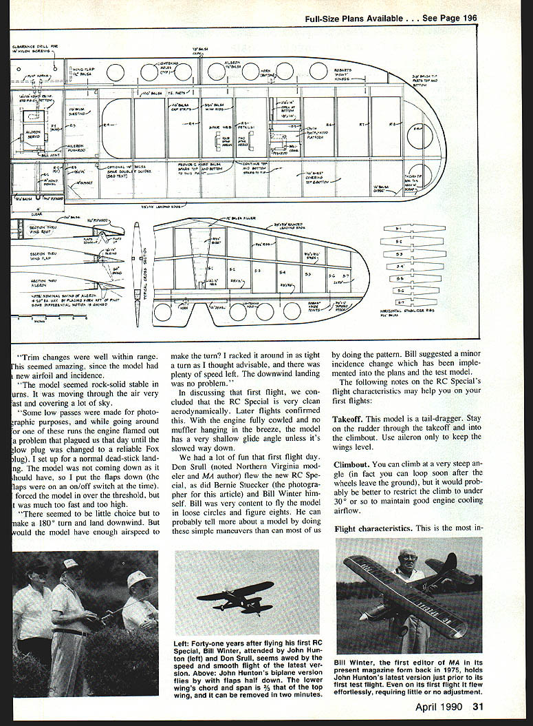
This is one of the most interesting models to fly—not overly stable yet not twitchy. It can be turned on a dime, looped tightly, and flown on the edge of a stall without concern. With the flaps down the model will seem to hover. Trim changes were well within range despite the new airfoil and incidence.
The RC Special is very clean aerodynamically. With the engine fully cowled and no muffler hanging in the breeze, the model has a very shallow glide angle unless slowed significantly.
The model feels rock-solid stable in turns and covers a lot of sky quickly. Bill Winter preferred flying loose circles and figure eights and could deduce a great deal about the model's behavior from those simple maneuvers. He suggested a minor incidence change that has been implemented in the plans and the test model.
Landing
- The RC Special is a very slippery and clean airplane. Without flaps the angle of glide is very shallow, which makes it difficult to get the model down in a restricted area.
- Be sure your engine is capable of a very slow idle.
- Use the flaps if you are confident with them; with flaps on you can fly the model very slowly without fear of stalling and attain a good rate of descent.
- Establish pitch-trim positions for flaps-on and flaps-off so the flaps can be used reliably on landing.
- Radios capable of mixing flaps with elevator trim provide more precise control.
The author found the airframe strong and tolerant of less-than-perfect landings.
Additional notes and recommendations
- The prototype featured an inverted .40-sized engine installation to retain the authentic theme of the 1947 design with its inverted Ohlsson .60 ignition engine. The cowl can be modified for an upright or side mounting if desired.
- A pressure cowl (as detailed in the plans) is an authentic and aerodynamically clean alternative but requires more work to build.
- For engines: a two-stroke .40 is adequate (the .40 turns an 11 x 4 prop at 15,000 rpm). If a four-stroke is contemplated, consider a Saito .60 or an Enya .46.
- The author favors airfoils with a long Phillips entry, a stay-back to the main spar, and a convenient flat bottom from there to the trailing edge. If such an airfoil is set at a slight negative angle (the prototype uses 2° negative), it behaves like a semisymmetrical section—giving flatter, faster power flight with less down trim and less tendency to climb steeply at high cruise. At +2° negative, a maximum one-quarter down elevator suits inverted flight while maintaining pleasant right-side-up handling.
- Transmitter mixing of elevator trim with flap deflection is recommended for best control during outside loops and rapid touch-and-go maneuvers.
Acknowledgments: Thanks to Bill Winter, John Hunton, Bill Kaluf, Ken Makepeace, and all the modelers who contributed plans, photos, and flight-testing that made this updated RC Special possible. Compared to its 1947 ancestor, the 47/88 RC Special is a thoroughly modern, high-performance interpretation of a Golden Age classic.
Transcribed from original scans by AI. Minor OCR errors may remain.

