
A-7E Corsair II
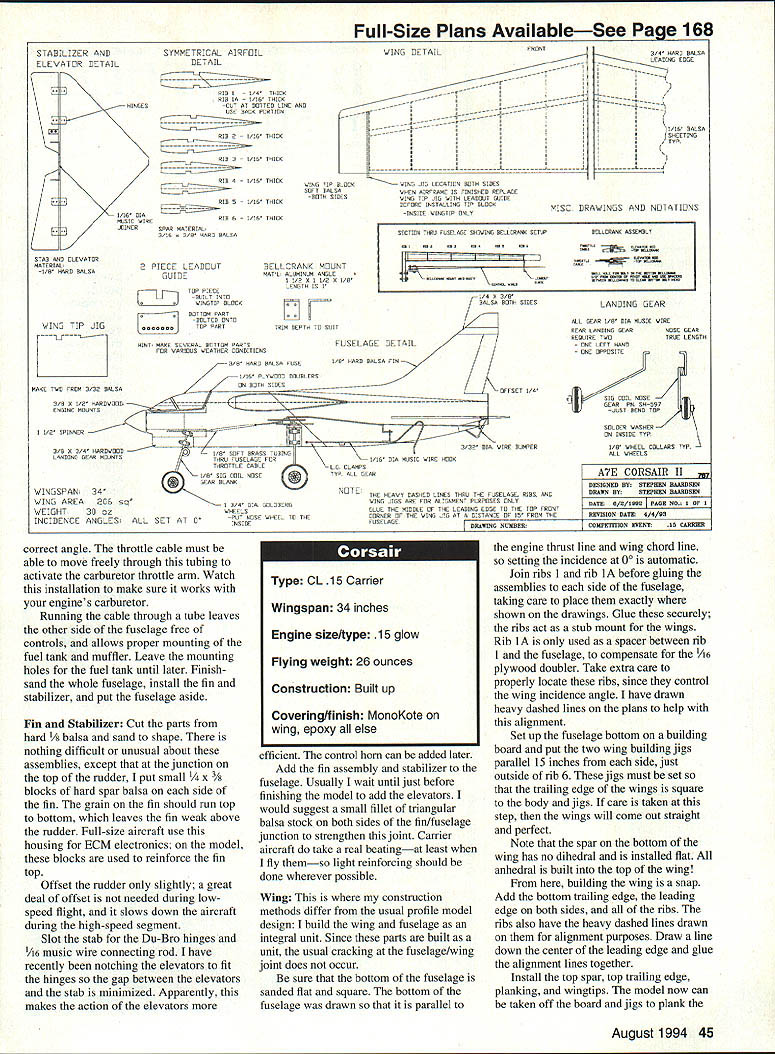
Stephen Baardsen
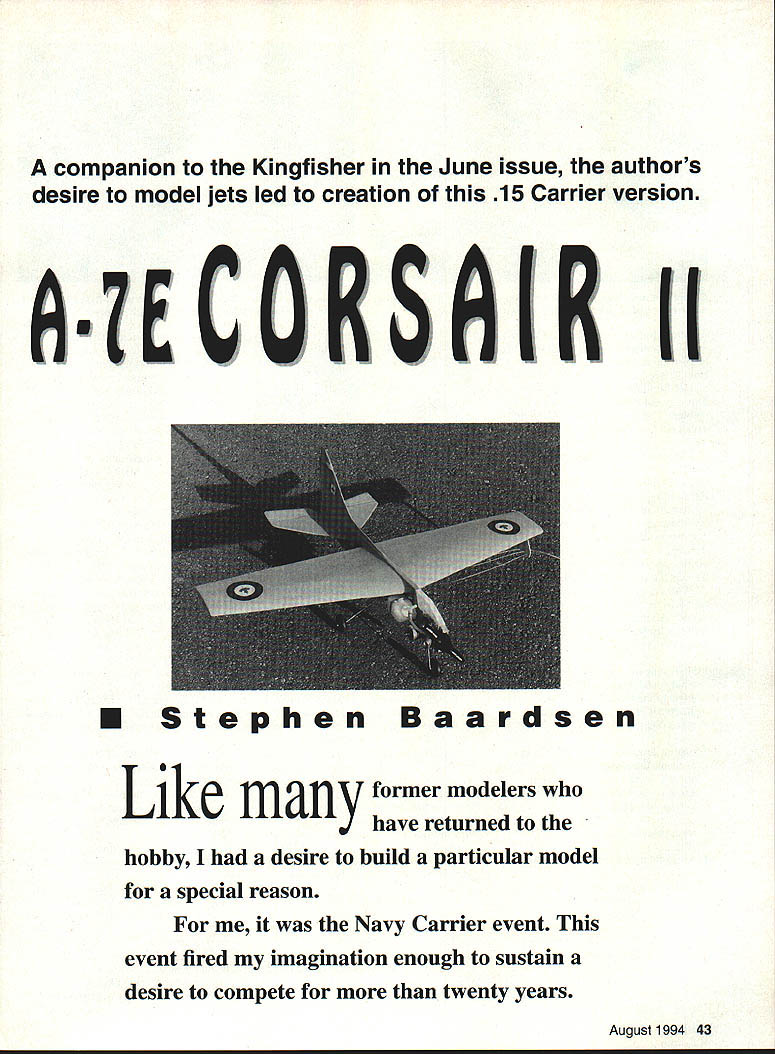
A companion to the Kingfisher in the June issue, the author's desire to model jets led to creation of this .15 Carrier version.
Like many former modelers who have returned to the hobby, I had a desire to build a particular model for a special reason. For me it was the Navy Carrier event. This event fired my imagination enough to sustain a desire to compete for more than twenty years.
After I decided to build a Carrier model and compete in local contests, a big problem arose: which aircraft should I build? Since I had always been a scratch builder, building from plans was not a deterrent, but finding plans to suit was a problem: I wanted to fly jets! The world's navies fly jets, and I wanted to as well.
I found a set of A-4 Skyhawk plans for the .15 Profile Carrier event from Gerry Deneau of Denver, Colorado. His A-4 flew very well, particularly in calm air, but its low-mounted delta wing suggested another design might be better in wind. After consulting local experts in Canada and Washington state, I defined an ideal .15 Profile Carrier model design:
- High wing location to achieve stability in windy conditions due to a pendulum effect of the weight hanging below the center of lift, particularly at low speed.
- Engine thrust line below the center of lift so power naturally rotates the nose up — useful for sustaining low-speed flight.
- Must be a Navy jet aircraft.
- All-flying tail for better control (later revised).
- Larger wing area than usual for a .15 engine to increase drag at high angles of attack.
- Bellcrank mounted outside the wing, using adjustable leadouts for trim corrections and center-of-gravity considerations.
- A lightweight model for faster acceleration off the deck.
- A variety of available color schemes.
- Fuselage-mounted landing gear for ease of maintenance and lighter overall weight.
While reading an aircraft magazine I spotted an A-7E Corsair II being catapulted off a carrier — it fit the list perfectly. I obtained three-view drawings and drew up rough plans. The fuselage profile was made to fit a 4" plank of balsa, which scaled well for the fuselage length. The fin and rudder were directly scaled up; as an attack aircraft the A-7E has a generous fin area. I borrowed the wing from Gerry Deneau's Wildcat design, using a straight trailing edge that matched the desired chord.
The prototype balanced correctly with no added weight, but the all-flying tail proved problematic and was removed for the Mark II. The Mark II performs better due to slightly larger wing area, a different airfoil, revised bellcrank mounting location, and lighter weight. The lesson learned: the stabilizer area is important as drag in the low-speed regime — the tail slows the model at high angles of attack. On to the building!
CONSTRUCTION
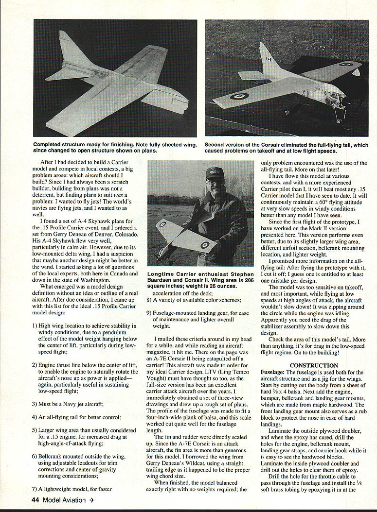
Note: fully sheeted wing.
Fuselage
The fuselage is built as a box-type structure and serves as a jig for the wing saddle. Start by cutting the body from hard 3/8" x 4" balsa sheet. Add the engine bumper, bellcrank and landing gear mounts made from maple hardwood. The front landing gear mount also serves as a rub block to protect the nose in case of hard landings.
Laminate an outside plywood doubler with epoxy. When cured, drill holes for the engine, bellcrank mount, landing gear straps, and carrier hook while the hardwood blocks are visible. Laminate an inside plywood doubler and drill out the holes to clear the carrier hooks. Drill a hole for the throttle cable to pass through the fuselage and install 5/32" soft brass tubing, epoxying it at the firewall. The completed structure is then ready for finishing.
The second version of the Corsair eliminated the full-flying tail because the open-structure stabilizer shown on the original plans caused sensitivity problems on takeoff and at low flight speeds.
Fin and Stabilizer
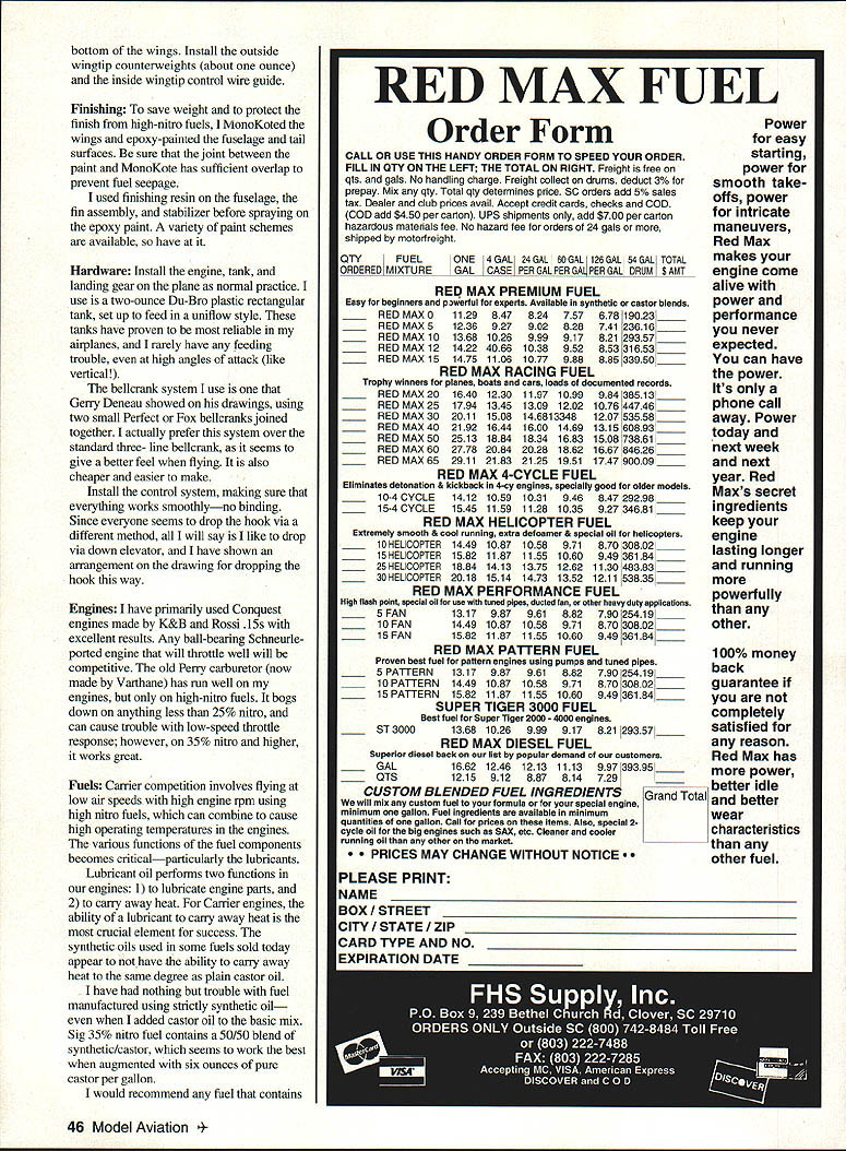
Cut the fin and stabilizer parts from hard 1/8" balsa and sand to shape. At the junction on top of the rudder, add small 1/4" x 3/8" blocks of hard spar balsa on each side of the fin to reinforce the fin top; the fin grain should run top to bottom. Slot the stabilizer for Du-Bro hinges and install the 1/16" music wire connecting rod. Minimize the gap between elevators and stab for more efficient elevator action. Offset the rudder only slightly — a large offset is unnecessary at low speed and slows the model during the high-speed segment.
Add the fin assembly and stabilizer to the fuselage. A small fillet of triangular balsa stock on both sides of the fin/fuselage junction will strengthen this joint — useful since carrier aircraft take a real beating.
Wing
My construction method differs from the usual profile model: I build the wing and fuselage as an integral unit to avoid cracking at the fuselage/wing joint. Be sure the bottom of the fuselage is sanded flat and square; the bottom was drawn parallel to the engine thrust line and wing chord, so setting the incidence at 0° is automatic.
Join rib 1 and rib 1A before gluing the assemblies to each side of the fuselage, taking care to place them exactly as shown on the plans. Glue these securely; rib 1 acts as a strut mount for the wings. Rib 1A is used as a spacer between rib 1 and the fuselage to compensate for the 1/16" plywood doubler. Properly locate these ribs since they control wing incidence; heavy dashed alignment lines are drawn on the plans and ribs.
Set the fuselage bottom on a building board and put two wing building jigs parallel 15" from each side, just outside rib 6. The jigs must be set so the trailing edge of the wings is square to the body and jigs. If care is taken here, the wings will come out straight.
Note that the bottom spar of the wing has no dihedral and is installed flat; all dihedral is built into the top of the wing.
From here, build the wing in the usual manner: add the bottom trailing edge, leading edge on both sides, and all ribs (aligning dashed lines). Draw a line down the center of the leading edge and glue the alignment lines together. Install the top spar, top trailing edge, planking, and wingtips. The model may then be taken off the board and jigs to plank the top of the wing. Install the outside wingtip counterweights (about one ounce) and the inside wingtip control wire guide.
Specifications
- Type: CL .15 Carrier
- Wingspan: 34 in
- Engine size/type: .15 glow
- Flying weight: 26 oz
- Construction: Built up
- Covering/finish: MonoKote on wing, epoxy on fuselage and tail surfaces
Finishing
To save weight and protect the finish from high-nitro fuels, MonoKote the wings and epoxy-paint the fuselage and tail surfaces. Ensure the joint between paint and MonoKote has sufficient overlap to prevent fuel seepage. I used finishing resin on the fuselage, fin assembly, and stabilizer before spraying epoxy paint. A variety of paint schemes are possible.
Hardware
Install engine, tank, and landing gear as normal. I use a 2 oz Du-Bro plastic rectangular tank set up to feed in a uniflow style; these have proven reliable even at high angles of attack. The bellcrank system shown on Gerry Deneau's drawings uses two small Ferrule or Fox bellcranks joined together. I prefer this over the standard three-line bellcrank — it gives a better feel, is lighter, and easier to make.
Install the control system making sure everything works smoothly with no binding. For the carrier hook I prefer a drop via down-elevator; an arrangement for that method is shown on the drawings.
Engines
I have primarily used Conquest engines by K&B and Rossi .15s with excellent results. Any ball-bearing Schnuerle-ported engine that throttles well will be competitive. The old Perry carburetor (now made by Varthane) has run well on my engines but only on high-nitro fuels; it bogs on less than 25% nitro and can cause low-speed throttle-response trouble. At 35% nitro and higher it works great.
Fuels
Carrier competition involves low airspeeds with high engine rpm using high-nitro fuels; this can cause high engine operating temperatures. Fuel lubricants perform two functions: lubricate parts and carry away heat. For Carrier engines, the ability of the lubricant to carry heat away is critical. Synthetic oils used in some fuels do not carry away heat as well as plain castor oil. I had problems with strictly synthetic-oil fuels even when augmenting with castor. Six 35% nitro fuel that contains a 50/50 blend of synthetic/castor, augmented with six ounces of pure castor per gallon, worked best for me.
I recommend fuels with an overall lubricant content around 22–23% with at least 14–15% pure castor. Since switching to this blend I've had no trouble with engines and eliminated high-nitro heat issues during lean runs.
Foam Wing Cores
John Hall of Tacoma, Washington has made wing cores available for this model. He can be reached at (206) 535-1034 or by mail at: 20197 50th Ave. East Tacoma, WA 98446-5301
Flying and Trimming
Balance the aircraft about 2" back from the leading edge for initial flights. Move the balance point back until the airplane begins to "hunt" in high-speed flight, then move it forward until the hunting stops.
To set up adjustable leadouts, hang the airplane by the control wires using hooks so the nose hangs down slightly; this should put the leadouts behind the center of gravity.
Check the wing angle from the front: if the control wire exit is at the top of the guide (12 o'clock position), the wing should hang slightly angled with the inside wingtip at 11 o'clock and the outside wingtip at 5 o'clock. This ensures the model flies with the outside wingtip slightly down at all times — a very stable attitude in all conditions, especially wind.
The rear fuselage-mounted landing gear makes landings smooth but limits rotation for takeoff from a deck run. Therefore the nose gear should be at least 1-3/4" longer to position the model properly for takeoff. Full-size A-7 Corsairs sit on the deck with a similar attitude.
I hope you enjoy building and flying the Corsair as much as I have. Keep your hooks dry!
Acknowledgments
Thanks to Gerry Deneau, Ron Salo, Bruce Duncan, John Hall, Greg and Ron Beers, Orin Humphries, Paul Gibeault, and all the others whom I pestered for information over the years.
Transcribed from original scans by AI. Minor OCR errors may remain.

