

A1H Skyraider
A.A. Lidberg
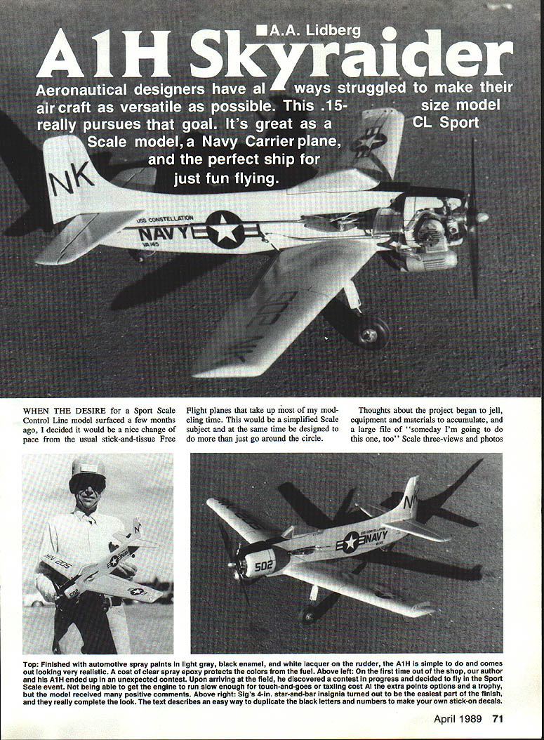
Aeronautical designers have always struggled to make their aircraft as versatile as possible. This .15-size model really pursues that goal. It's great as a CL Sport Scale model, a Navy carrier plane, and the perfect ship for just fun flying.
When the desire for a Sport Scale Control Line model surfaced, I decided a simplified scale subject would be a nice change from the usual stick-and-tissue free-flight planes. I raided a pile of photos I’d taken of an A1H Skyraider and a clipped Douglas three-view (Profile Publication No. 60) — enough data on hand to begin.
Keeping the A1H as a sport profile model meant including the usual necessary model elements without overly detracting from scale effects. The end product shows conventional scale outlines, dihedral, landing-gear type, wing shape, and a skinny fuselage; a quarter-inch of excess elevator width and some other minor compromises are the only obvious nonscale features. I chose authentic markings and worked out a simplified method of duplicating them. The resulting model looks good and has fine flying abilities.
Two comments I’ve heard from other modelers sum it up well: “It doesn’t fly like a .15 — it looks and acts like a much larger model,” and “The Skyraider doesn’t look like a profile airplane.” The first is accurate — the model flies fairly fast, has a good speed range, and stays out on the lines very well. The second probably goes to the cowling, which sets the A1H apart from pure profile-bodied models.
The AD-series Douglas Skyraiders are fascinating subjects. Design efforts (initially the XBT2D-1, Dauntless II) began in 1944; the first flight was April 1945, and 548 aircraft were ordered shortly afterward. Early on, the name changed to Skyraider and Navy designations changed BT2D-1 to AD-1. The type evolved through AD-7 and served in Korea and Vietnam.
Because the AD went through many permutations, the sport-scale project can be finished several ways — XBT2D-1 in silver; BT2D-1 in navy blue and white markings; AD-6 in light gray; or A1H (designation change from AD-6) in gray. The prototype model is an A1H in gray, since black markings based on old photos are easy to reproduce.
Construction
Body (fuselage)
- The fuselage is plank construction over 1/8-in. sheet balsa.
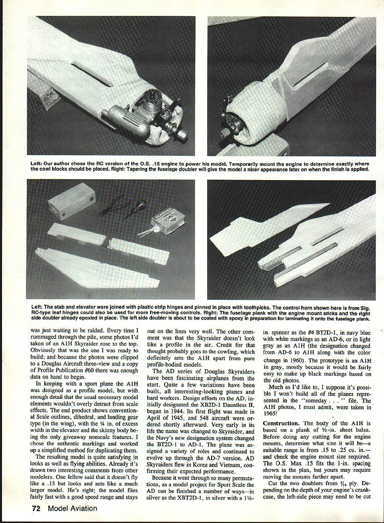
- Before cutting, decide on an engine (suitable range .15–.25 cu in) and check required engine-mount spacing. An O.S. Max .15 fits the 1-in. spacing shown on the plan; your engine may require moving the mounts farther apart.
- Cut two doublers from 1/16-in. ply. Depending on the crankcase depth, the left-side doubler may need a clearance cutout between the mount sticks. Taper the rear edge of the doubler with a rasp and sandpaper for a nice finish.
- Epoxy the mount sticks in place, then epoxy the doublers to the fuselage. Drill the engine-mounting holes and fit blind nuts for the cowl and engine mounting — blind nuts work well for mounting.
- Cut out clearance for the bellcrank and its platform.
Cowl
- The cowl is decorative but worth the extra work. Begin roughing it from two blocks (add 1/4-in. sheet to the right-side block to increase width) plus a 1/4-in. sheet ring.
- Remove enough material on the right block to clear the engine, throttle, needle valve, fuel line, and muffler. Cut engine-clearance holes first, then carve the exterior shape.
- The cowl pieces are permanently attached to the fuselage after creating enough clearance to install and remove the engine through the openings.
- The cowling is somewhat offset to accommodate the propeller center on one surface of the flat profile body. The offset isn't obvious once painted and finished.
- The muffler is removed to access engine-mount screws and then reinstalled. Use of a muffler is highly recommended — it can help keep or gain flying sites and reduces flight-line jitters.
Wing
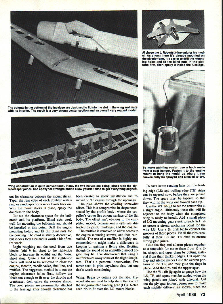
- Cut out the ribs. Plywood ribs are used where the wing-mounted landing gear (LG) mounts to help share the load; notch each rib to fit over the LG mount blocks.
- Taper the leading-edge (LE) and trailing-edge (TE) strips now to save sanding later. The spars must be tapered toward the tips.
- Use the W1 rib jig to set the center ribs at a slight angle — these ribs will lie adjacent to the fuselage when the wing is installed.
- Add a small piece of LG mounting stock to each W1 rib to anchor the wire LG. Use a 3/32-in. drill bit to connect the grooves of these pieces.
- Fit all ribs carefully at their LE and TE ends for strong glue joints.
- Glue the flap and aileron pieces together as a sandwich (or carve from 1/8 x 2-in. sheet), taper them by removing thickness at the edges, then cut apart into flap and aileron sections. Glue the ailerons to the TE and tack-glue the flaps.
- Add tips and the upper spar; note that wings taper in thickness.
- Join the panels either “in the air” or pinned down with tips blocked up. One method: block the tips on the board, glue panels together, then remove the wing to fit the joiners. Clothespins help clamp joiners.
- Add wing sheeting and sand the bottom of the center section flat to blend with the fuselage.
- Join fuselage and wing. You may have to thin the fuselage or open up the wing center slot for a good fit. This joint is very strong with epoxy — double-check alignment before it sets.
Landing gear, stabilizer, and elevators
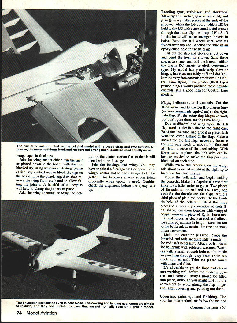
- Make landing gear wires to fit and glue 1/8-in.-sq. filler pieces at the ends of the grooves.
- Make LG doors; hold them to the LG with small wood screws through brass clips. A drop of Hot Stuff in the holes will create stronger threads in balsa.
- Bend the tail-wheel wire with a folded-over top end and anchor it in an epoxy-filled hole in the fuselage. Use a 3/4-in. or 1-in. tail wheel per the hardware list.
- Cut out the stabilizer and elevators; cut down and bend the horn as shown on the plan. Sand to shape and add hinges — either plastic RC strip or cloth-over/under types. Plastic strip hinges are stiff and can reduce control freedom; Klett-style pinned hinges give more flexible controls, preferred for Control Line flying.
Flaps, bellcrank, and controls
- Cut the flaps away and fit a Du-Bro aileron horn (or your equivalent) to the right flap. Fit other flap hinges but don't necessarily glue them until later.
- Because of dihedral and wing taper, the left flap needs a flexible link to the right flap. Bend the link wire, glue it flush with the lower surface of the flap, and make a socket (flattened tubing) so the link can move fore and aft. Bend the link to make flap positions identical on each side.
- While working on the wing, add about 1/4 oz. of weight to the right tip to help maintain line tension.
- Mount the bellcrank and begin making the controls. The flap/throttle rod is easiest to do first since it’s harder to access. Use two threaded rods (one for throttle, one for flaps) and a plain rod that hooks into the bellcrank’s throttle hole.
- Bend the three rods close to final shape, join them with wrapped copper wire or 3/32-in. brass tubing, and solder. Add clevises at each end for length adjustment. Bend to the bellcrank for free, full movement.
- Make the elevator pushrod. Threaded-end rods are stiff so a guide isn’t necessary. Attach both rods at the bellcrank with soldered washers made from punched scrap brass or tin can stock, trimmed round with snips and files.
- It’s advisable to get flaps and elevators working well before covering and painting. Fit hinges into place, but you may choose to defer gluing flap hinges until after covering and painting.
Covering, painting, and finishing
- Use your preferred covering method.
- Hang the plane by engine-mount bolts (bend a hanger from coat-hanger wire) so it can be painted while suspended.
- For markings: on the prototype I masked block letters and numbers with artist’s frisket and sprayed black enamel. Smaller letters were Leroy lettering on clear sticky decal material (Peck Polymers). Sig’s 4-in. star-and-bar insignia were used.
- An easier method: make Xerox copies of letters, cut and arrange them on 8½ x 11-in. paper (secure with tape or rubber cement), then have a blueprint shop Xerox the markings onto sticky-back material. Cut apart and use like sticky-back decals (about $1 per sheet).
- Mask and paint anti-glare panel, rear faces of cowl, and step panels black. Paint the canopy silver, white, or light blue as desired; the rudder should be white.
- Add panel lines, trim-tab hinge lines, and other small details with a drafting pen-and-ink or a marker labeled “permanent” for use on film or plastic.
- Let everything dry about four days, then apply two coats of Black Baron clear spray epoxy. This material will withstand up to about 15% nitro fuels after aging for a week.
Final assembly
- Fit LG with doors, straps, and screws; attach wheels with soldered washers or wheel collars.
- Add bellcrank and pushrods, and make solid-wire lead-outs. With elevators neutral and throttle at high-speed position, make throttle lead-out 3½ in. longer than elevator lead-outs.
- Install engine and muffler. Attach fuel tank with silicone glue, rubber bands, or brass strap and wood screws. If the muffler has a pressure fitting, run a line from it to the tank’s lower vent; remove the line at the muffler end for overflow when filling, then reattach. Cap the top vent with a plugged or folded-over fuel line to prevent drips.
- Balance: the A1H can balance over a considerable range and still be flyable. With the CG far forward the plane is highly stable and slow to respond; rearward CG increases sensitivity. The prototype balances just behind the wing’s leading edge at the fuselage with the tank empty — a stable, easy plane that glides well with the engine off.
- With a heavier engine, add tail weight to move the balance point forward to the wing’s leading edge if needed. Some fliers add ballast to improve slow-speed flight.
- Before flying, do a rudder check, hook up the five flying lines and handler, and ensure throttle and flaps move correctly from the third line.
Flying
- The A1H is a tail-dragger. Maintain up-elevator on takeoff to avoid nosing over, especially from grass.
- Have a helper hold the model for first flights and release it at high speed, flaps-up. As you learn the plane you can try taxiing and taking off under power.
- Set the throttle speed low enough for touch-and-go maneuvers on landing under power.
- The linked throttle-and-flaps arrangement is unusual but more orthodox than latch-type carrier flaps. Carrier-type flaps and a hook can be adapted later if desired.
- Another flap option: a sliding-link arrangement where flaps are spring-down and a sliding link raises them during the last third of throttle travel. This allows near-full-power takeoffs with flaps down, then flaps up for high-speed flight.
- Model projects often require help — special thanks to John Patton for technical assistance.
If a Sport Scale Control Line model suits your needs, the A1H won’t disappoint. It’s durable and should bring many hours of flying pleasure.
Hardware, etc. Used on the A1H
(All items available from a well-equipped hobby shop or from Sig.)
- O.S. Max .15 with throttle and muffler; 8x4 Master Airscrew prop (engines between .15 and .25 cu in are suitable)
- Perfect #21 short Senior wedge tank, 1 oz. capacity
- 1/4 x .025-in. brass strip (K&S) plus screws for tank mount
- 4-40 engine and bellcrank mounting bolts with blind nuts (need six)
- J. Roberts standard upright plane control unit and handle (or similar LR products)
- Du-Bro strip aileron horn and connectors
- Sig 4-in. horn
- Goldberg Klett hinges (need seven)
- Threaded pushrods (one at least 24-in., two 6-in.)
- Nylon small clevises (need three)
- Perfect 2-in. wheels
- 3/4-in. or 1-in. tail wheel
- Sig landing gear mounts, 5/16 x 3/8-in. (need two)
- Sig landing gear straps
- Flying lines: .015 stranded wire, three 52-ft. lines
- Plasticote Car Color touch-up spray, 1979 Ford Dove Gray, stock #FM 8084, available at Pep Boys (two 6-oz. cans) — any acrylic lacquer marked suitable is probably OK
- Hot Stuff Super T for most joints
- Epoxy glue for specified joints
- Black Baron clear spray (one can)
- Nitrate dope (about 1/2 pint)
- Balsa and other materials as noted on the plan
Transcribed from original scans by AI. Minor OCR errors may remain.

