
Add a Simple Flap Feedback to Stabilize a Model Heli
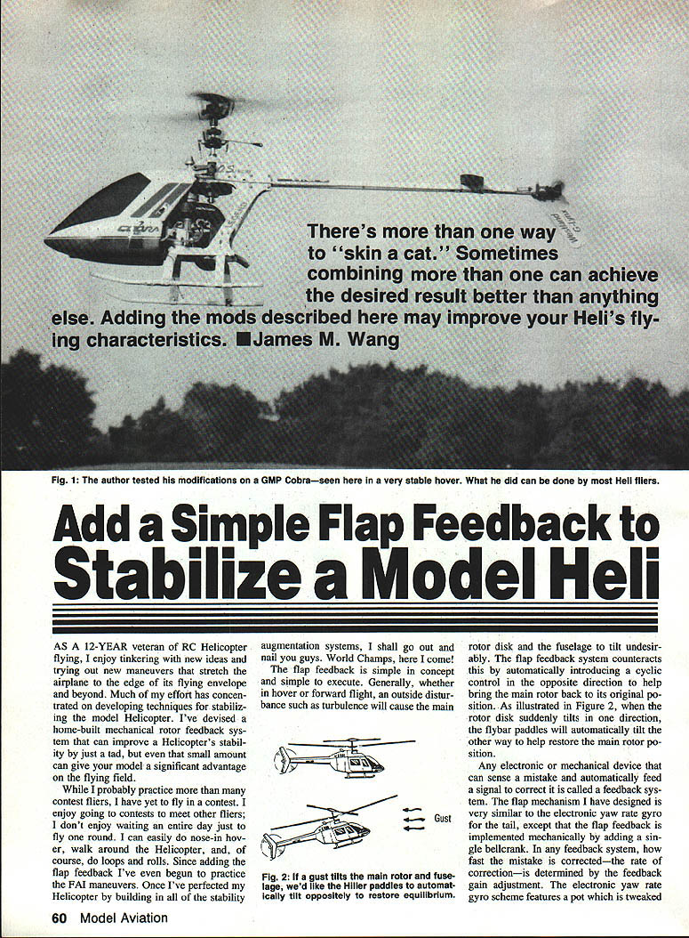
As a 12-year veteran of RC helicopter flying, I enjoy tinkering with new ideas and trying out maneuvers that stretch the machine to the edge of its flying envelope and beyond. Much of my effort has concentrated on developing techniques for stabilizing the model helicopter. I've devised a home-built mechanical rotor feedback system that can improve a helicopter's stability by a small amount — but even that small gain can give your model a significant advantage on the flying field.
I practice more than many contest fliers but have yet to fly in a contest. I enjoy meeting other fliers; I don't enjoy waiting an entire day just to fly one round. I can do nose-in hover, walk around the helicopter, and perform loops and rolls. Since adding the flap feedback I've even begun to practice the FAI maneuvers. Once I've perfected my helicopter by building in all of the stability augmentation systems, I'll be ready to compete.
How the flap feedback works
The flap feedback is simple in concept and simple to execute. Whether in hover or forward flight, an outside disturbance such as turbulence will cause the main rotor disk and the fuselage to tilt undesirably. The flap feedback system counteracts this by automatically introducing a cyclic control in the opposite direction to help return the main rotor to its original position.
- When the rotor disk suddenly tilts one way, the flybar paddles automatically tilt the other way to help restore the main rotor position (see Figure 2).
- Any electronic or mechanical device that senses a mistake and feeds a corrective signal is called a feedback system. The flap mechanism I designed is similar in function to an electronic yaw-rate gyro for the tail, except it is implemented mechanically by adding a single bellcrank.
In any feedback system, the rate at which a mistake is corrected is determined by the feedback gain. Electronic gyros use an adjustable pot; in the mechanical flap system, the gain is adjusted by changing the bellcrank geometry.
Adjusting feedback gain
To change the feedback gain in the mechanical flap system:
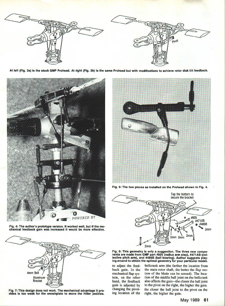
- Move the bellcrank pivot location farther from the main rotor shaft to sense flap motion more effectively.
- Adjust the middle ball joint position on the bellcrank: the closer that joint is to the pivot on the right, the higher the gain.
- Increase swashplate tilt angles if needed to retain control sensitivity — my swashplate now tilts 30° up and 30° down.
- Replace inner swashplate ball joints with longer ones to increase throw at the wash-in/wash-out scissor unit.
Experiment with bellcrank geometry to squeeze more gain out of the system. In my early configuration (Figure 3) I only achieved about 1° of paddle tilt for every 10° of main rotor tilt — a small improvement. Increasing the gain without diminishing paddle throw may require moving the middle ball joint and changing swashplate geometry.
Construction and implementation
- Figures 3 and 4 show the flap feedback scheme implemented on a GMP Cobra Prohead.
- The metal support and bellcrank can be made from 1/32" K&S sheet aluminum available at hobby shops. Figure 5 shows basic parts made from salvaged pieces; Figure 6 shows using off-the-shelf GMP parts.
- Ideally, the bellcrank pivot should be at the same height as the main rotor hub. This maximizes the vertical travel of the pivot point and the mechanical feedback gain.
An added benefit of the bellcrank system is improved rigidity of the paddle control setup. Before the modification, turning the paddle by hand caused discernible movement in the pitch and roll servos. With the new configuration and increased mechanical advantage, hand-turning the paddle produces almost no servo movement.
The first rotor-disk tilt scheme I tried (Figure 7) failed because the pushrod from the wash-in/wash-out unit was connected to the middle of the bellcrank arm, giving very low mechanical advantage. Moving the swashplate caused practically no paddle movement.
Delta-3 flap stabilization and Bell‑Hiller mixing ratio
The flap feedback concept can be adapted to many helicopter designs. Two related innovations I described earlier are the Delta-3 flap stabilization and the system for changing the Bell‑Hiller mixing ratio. These three modifications (flap feedback, Delta-3, Bell‑Hiller) can be used together on a single helicopter.
Delta-3 flap stabilization
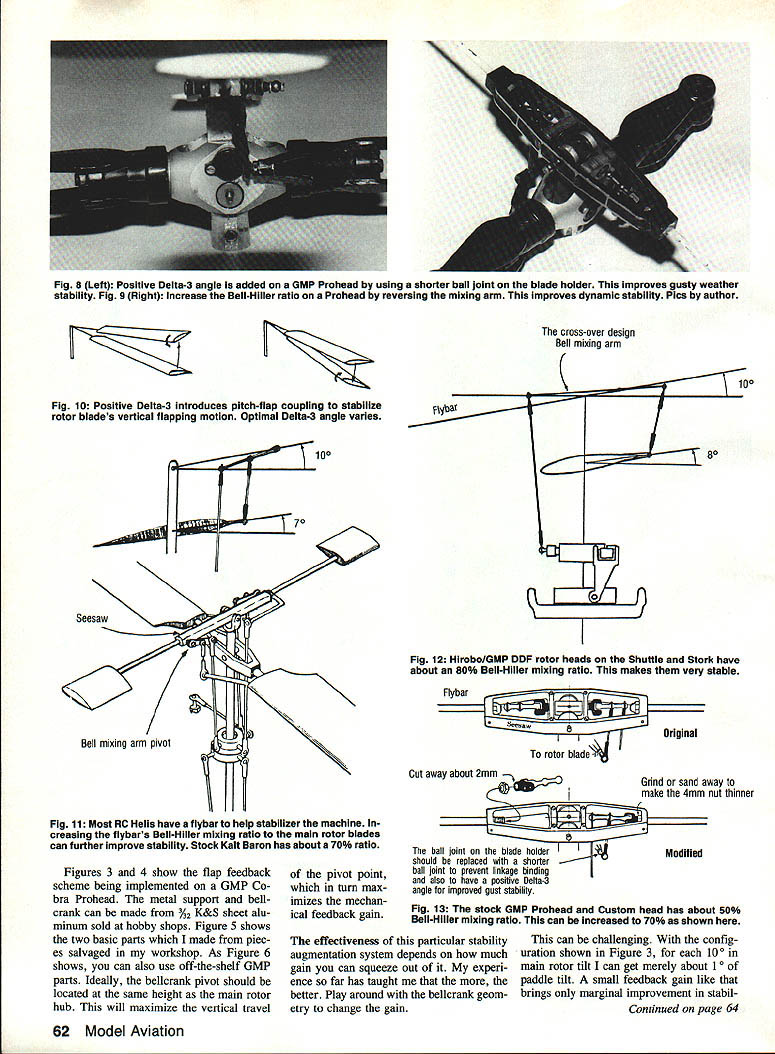
- The Delta-3 angle couples blade flapping to pitch in a stabilizing way.
- On a two-bladed teetering rotor (such as the Cobra), introduce the Delta-3 by replacing the original long ball joint on the blade holder with a shorter ball joint from the swashplate.
- When a blade flaps up, the Delta-3 geometry automatically reduces the pitch on that blade to bring it back down. When the blade flaps down, the Delta-3 increases pitch to bring it back up. This pitch-flap coupling is purely geometric (see Figure 10).
The optimal Delta-3 angle varies by model. A positive 20° works well for my Cobra. Full-size helicopters often use about 25° on the main rotor for gust stability; the Bell Jet Ranger uses 45° Delta-3 on the tail rotor. Experiment with ball-joint lengths to find the ideal angle for your model.
Both positive and negative Delta-3 can stabilize flapping blades, but negative Delta-3 slightly increases coning angle. Increased coning tends to improve dynamic stability, which may explain why some GMP Prohead pilots saw better stability with negative Delta-3. On articulated multi-blade rotors (e.g., a Schluter Champion), accidentally installing negative Delta-3 produced wildly flapping blades and tracking problems because those rotors can already develop large coning angles.
Bell‑Hiller mixing ratio
- The Bell‑Hiller mixing ratio (the flybar's mixing effect) is equivalent to a flybar feedback gain adjustment. Increasing the ratio is like cranking up a rate gyro's gain.
- Kalt uses about a 70% Bell‑Hiller mixing ratio: if the main rotor disk tilts 10°, the flybar produces about a 7° pitch change on the blades. This mechanical feedback helps stabilize the rotor.
- Some GMP models (Shuttle and Stork with the DDF head) achieve about 80% mixing by using a crossover mixing arm (Figure 12).
- Increasing the Bell‑Hiller mixing ratio from 50% to at least 70% is an easily performed modification (Figure 13). I tried a small gain increase on my Champion, but the improvement was barely noticeable.
The Kyosho Concept 30 uses an ingenious Hiller mixing system incorporated into a sliding swash-washout scissor unit and achieves nearly a 95% mixing ratio. This yields exceptional hovering stability for a mini-helicopter.
Examples, reports, and observations
- After my Delta-3 article (International Helicopter Magazine, No. 3), a flier in England reported that positive Delta-3 improved his Kalt 60EX.
- A modeler in South Africa said adding positive Delta-3 helped stabilize his four-bladed Schluter Champion — though his first attempt accidentally used negative Delta-3 and destabilized the rotor.
- On the GMP Prohead, some modelers reported that negative Delta-3 (achieved by extending the ball joint) improved stability, likely due to a slight increase in coning angle.
- The Concept 30 demonstrates that good preliminary design (rather than adding flybar weight as an afterthought) can markedly improve stability and performance.
Combining the modifications
Each of the three feedback systems stabilizes the main rotor disk by restoring blade equilibrium, but they act through different paths:
- Delta-3: senses blade flapping and corrects pitch to restore equilibrium (direct geometric coupling).
- Bell‑Hiller mixing: senses the difference between the tilted rotor disk and the flybar and implements a pitch change to restore equilibrium.
- Flap feedback: senses rotor-disk tilt and changes Hiller paddles to tilt the flybar and hence correct blade pitch (more indirect).
I suggest trying all three methods individually and in combination. They can have a synergistic effect: small improvements from each can add up to a meaningful overall gain.
Caveat: There's no guarantee these feedback concepts will work equally well on every model. As Ray Hosteler pointed out in his February 1989 "Hover" column (Radio Control Modeler), helicopters have many design variables that can overshadow feedback-system effects:
- flybar length
- paddle size, weight, and airfoil
- main blade length, weight, and airfoil
- shaft height
- and more
Because of these variables, the benefit of a given modification varies by model. A comprehensive article I plan will analyze these design variables; reading it with this piece should get you started on experiments to find the best geometry and gains for your model.
Practical tips
- The easiest ways to improve stability are adding flybar weight or changing paddles; flybar weight is the most commonly used strategy.
- Adding flybar weight may improve stability by about 10%; changing paddle properties might add another 5%.
- My flap feedback might add about 1%, Delta-3 about 2%, and increasing the Bell‑Hiller ratio about 3% — small individually but cumulatively useful in competition.
- Play with ball-joint lengths, bellcrank positions, and swashplate tilt to maximize mechanical gain without losing control sensitivity.
Ingenious tinkerers have kept our hobby and technology moving forward. Applying these feedback concepts may take hours of fiddling, but experimentation is the route to better performance. As the saying goes: no pain, no gain.
Conclusion
These three modifications — flap feedback, Delta-3, and increased Bell‑Hiller mixing — are proven, practical ways to improve helicopter stability. They are not ultimate answers, but together they can provide a competitive edge. Try them individually and in combination, document your changes, and iterate until you find the best setup for your model.
Transcribed from original scans by AI. Minor OCR errors may remain.

