
Adventures in Modeling: Tutor
By Bob Harrah
Introduction
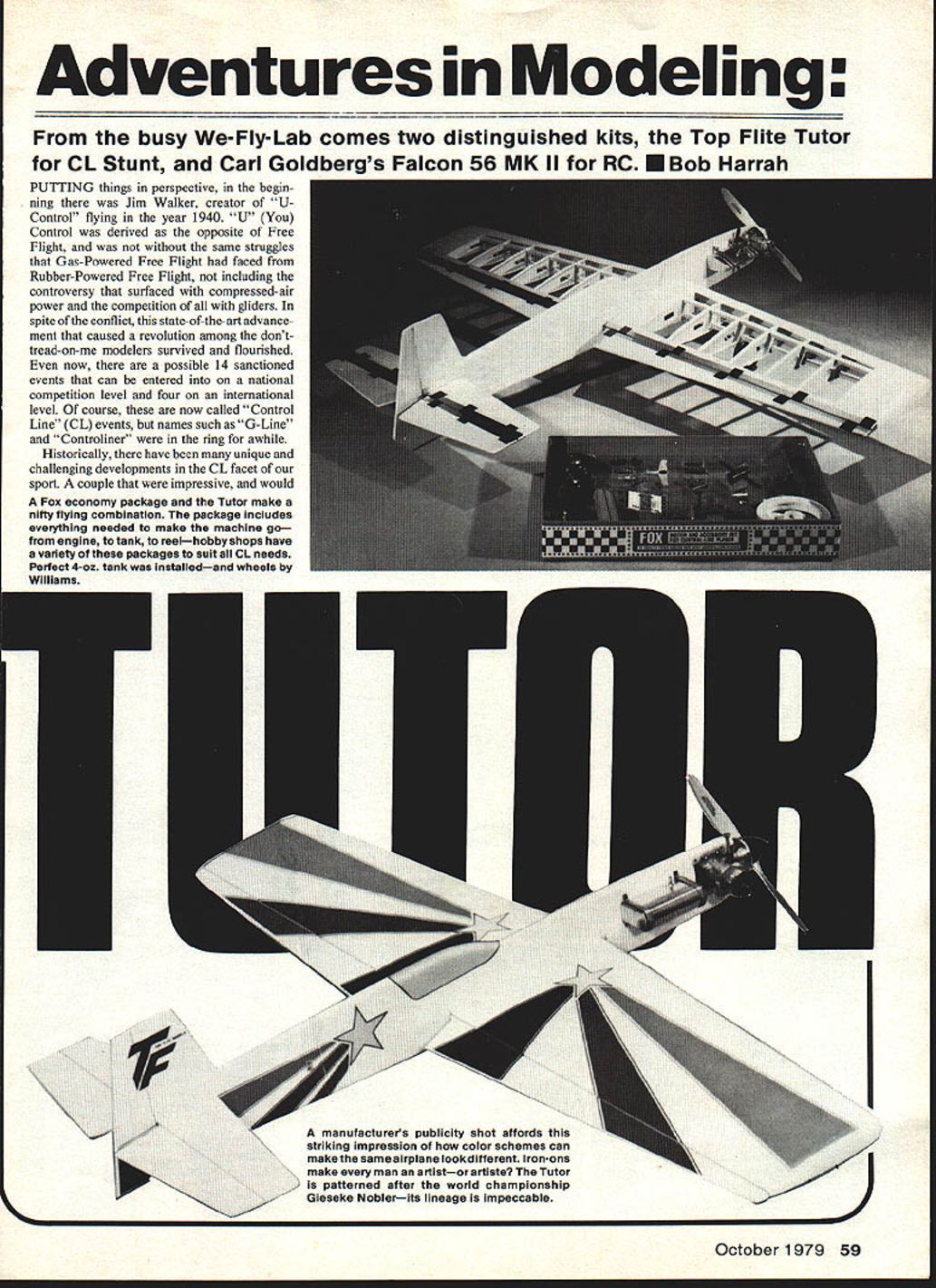
From the busy We-Fly-Lab come two distinguished kits: the Top Flite Tutor for control-line (CL) stunt, and Carl Goldberg's Falcon 56 MK II for radio control (RC). This article concentrates on the Top Flite Tutor and related products and developments.
History of Control Line
Putting things in perspective, in the beginning there was Jim Walker, creator of "U-Control" in 1940. "U" (You) Control was developed as the opposite of Free Flight and faced many of the same struggles that gas-powered free flight had faced earlier with rubber-powered free flight. There were controversies over compressed-air power and competition with gliders, yet this state-of-the-art advancement sparked a revolution among modelers and survived and flourished.
Today there are many sanctioned CL events—up to 14 at the national competition level and four internationally. Though now commonly called "Control Line," names such as "G-Line" and "Controliner" were once considered.
Notable historic CL developments
There have been many unique and challenging developments in CL modeling. Two notable examples:
- The 1/2A Mini Whirlaway speed model by Berkeley Models (vintage 1954). It could be flown with a .049 Thermal Hopper or an Atwood Wasp engine, featured preformed hollow aluminum wings, plywood stabilizer and rudder, a gutted solid balsa fuselage, and an astonishing wingspan of 8.25 inches.
- The "Ares," an Ambroid Models design that won national CL stunt for many years. It required craftsmanship and building techniques only found in the most sophisticated kits. Ares featured an inboard wing longer than the outboard wing, with weight added to the outboard wing—an arrangement also seen in earlier designs such as the Veco Chief.
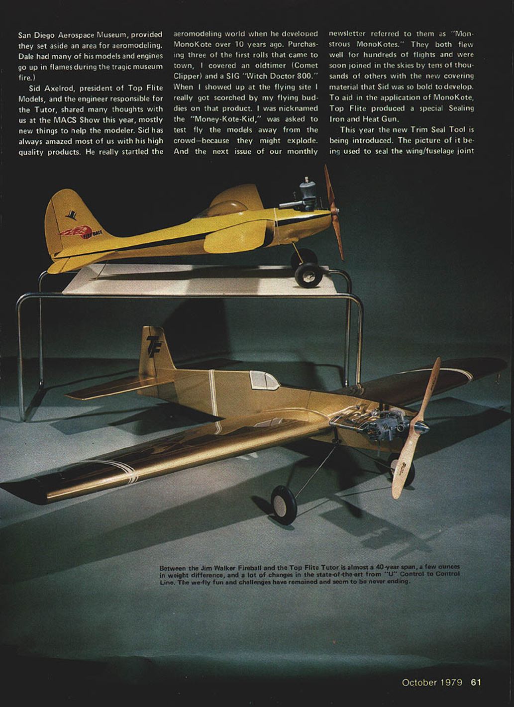
A picture pairing the Tutor with Jim Walker's "Fire Ball" helps illustrate what CL has evolved from. The Fire Ball shown was originally built by the late Dale Wiley and weighed 32 ounces ready-to-fly; the Tutor is about 30 ounces (less fuel) with over twice the wing area.
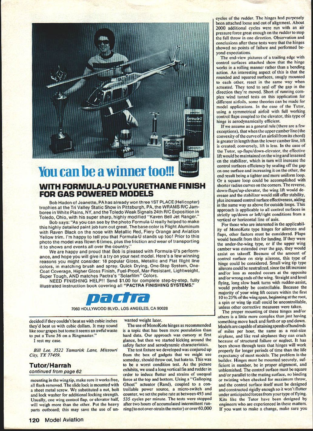
Top Flite, Sid Axelrod, and Innovations
Sid Axelrod, president of Top Flite Models and the engineer responsible for the Tutor, shared many ideas at the MACS Show. Sid has a long history of producing high-quality products and surprised the modeling world by developing MonoKote over a decade ago. Early adoption of MonoKote produced skepticism among some flyers, but the material proved durable and soon became widely used.
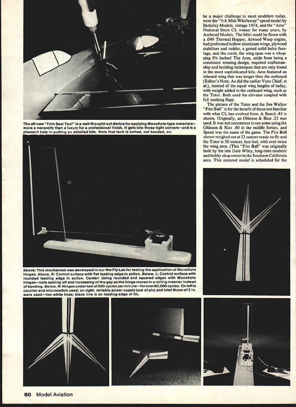
Top Flite produced accessories to help apply MonoKote, such as a special sealing iron and a heat gun. This year they introduced a Trim Seal Tool specifically for sealing wing/fuselage joints and fillets.
Trim Seal Tool features
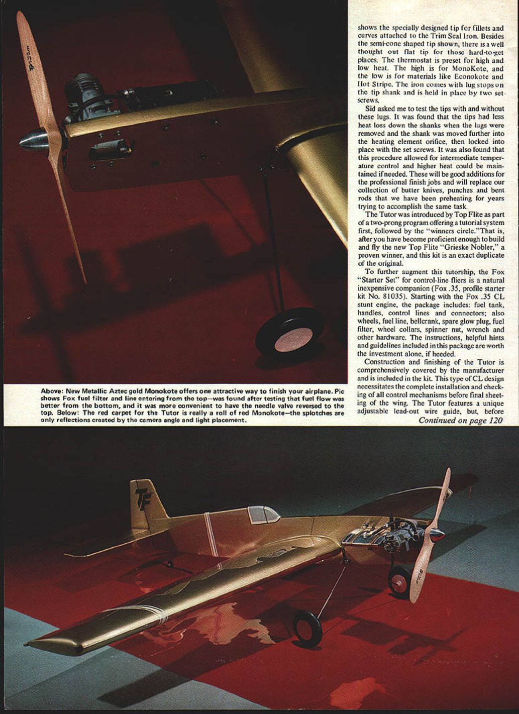
- Specially designed tip for fillets and curves (semi-cone shaped).
- Flat tip for hard-to-reach places.
- Preset thermostat with high and low heat settings (high for MonoKote; low for Econokote, Hot Stripe, etc.).
- Lug stops on the tip shank held by two set screws.
Testing revealed that removing the lug stops and seating the tip shank further into the heating element reduced heat loss and allowed intermediate temperature control. These tips are useful for professional finishes and replace improvised tools such as butter knives, punches, and bent rods.
The Tutor Kit and Starter Set
Top Flite introduced the Tutor as part of a two-prong program: a tutorial system followed by the "winners circle." After becoming proficient with the Tutor, a modeler can progress to building and flying the Top Flite Grieske Nobler, a proven winner and an exact duplicate of the original competition design.
To complement the Tutor, the Fox "Starter Set" for control-line fliers is an inexpensive and natural companion (Fox .35 profile starter kit No. 81035). The package includes the Fox .35 CL stunt engine plus:
- Fuel tank
- Handles
- Control lines and connectors
- Wheels
- Fuel line
- Bellcrank
- Spare glow plug
- Fuel filter
- Wheel collars
- Spinner nut
- Wrench
- Other hardware
The instructions, helpful hints, and guidelines included in the package are valuable for beginners.
Construction and Control Mechanisms
Construction and finishing of the Tutor are comprehensively covered in the kit instructions. This CL design requires complete installation and checking of all control mechanisms before final wing sheeting.
Highlights and tips:
- The Tutor features an adjustable lead-out wire guide. Before mounting in the wing tip, ensure it works freely and remove all flash.
- The slide lock is mounted with a sheet metal screw in the kit; substituting a nut, bolt, and lock washer provides additional locking strength.
- Balance control surfaces: one elevator half will often weigh more than the other—place heavier parts outboard to avoid adding unwanted ballast later.
MonoKote Hinges: Tests and Observations
The use of MonoKote-type hinges (adhesive film hinges) has been debated. To assess their durability and suitability, a worst-condition test fixture was developed.
Test setup
- A long vertical fin and rudder were used to induce flutter and unequal forces top-to-bottom.
- A "Galloping Ghost" actuator (Rand) was coupled to a controllable power source, a micro-switch, and a counter.
- Pulse rate was set between 495 and 535 cycles per minute.
- Tests were stopped after two hours of accumulated intermittent running (to avoid overstressing the motor), or after over 60,000 cycles of the rudder.
- Hinges were deliberately attached loose and out of alignment to stress them.
- An additional ~2,000 cycles were run with air pressure sufficient to stop the full throw in one direction.
Results
The hinges showed no points of failure and performed beyond expectations. End-view photos showed the hinge operated in a rolling manner rather than a bending action. Rounded and squared mating surfaces reacted similarly when actuated and tended to seal the gap in the direction of movement.
Aerodynamic Effects of MonoKote Hinges
On the Tutor, which uses a symmetrical airfoil with full working control flaps coupled to the elevator, this type of hinge is aerodynamically efficient.
Basic aerodynamic reasoning:
- If the upper camber line (the convex curve of the airfoil) is longer than the lower camber line, lift is produced; conversely, lift is reduced when the upper camber is shorter.
- With up-flaps and down-elevator, effective lift on the wing is maintained while lift on the stabilizer is lessened; the hinge seals the gap on one surface and increases it on the other, producing a tighter, more uniform loop.
- Reverse deflection (down-flaps/up-elevator) reduces wing lift but increases stabilizer effectiveness, aiding outside loops.
- These principles apply to strictly up/down or left/right control-surface motions relative to a vertical or horizontal axis.
Applicability to Ailerons and Flaps
When considering MonoKote hinges for ailerons and flaps, several factors must be considered:
- Flaps: Adhesive-film hinges can benefit landing flaps. Under-the-wing flaps or those with upper-camber continuity over the gap can assist takeoff.
- Ailerons: Strip ailerons might be candidates for this hinge type, but their large control surface area complicates matters. Small tip strip ailerons could be neutralized because lift changes occur at the opposite or undesired wing ends.
- Stall considerations: Since most wing lift occurs in the first 10–25% of the span near the root, tip stalls or spins could be uncontrollable unless corrective measures are implemented.
- In general, hinge mounting, control-surface rigidity, and proper alignment are critical for safety and performance.
Hinge Installation and Safety
Proper hinge installation is more complex than simply allowing movement. Models can reach very high speeds and, like full-size aircraft, can fail due to structural faults or neglect. Tests suggest that hinges, when properly mounted, will outlast the typical life of many models. The real problem is improper construction.
Guidelines:
- Mount hinges securely and in sufficient number.
- Ensure proper alignment; mating surfaces must be square and parallel.
- Check for no binding or twisting over full control throw.
- Build control surfaces rigidly so they do not flutter under expected loads.
- If modifying a kit design, understand the consequences or seek expert advice.
Control-line flying often occurs in more populated areas and attracts spectators. Follow all manufacturers' safety recommendations and adhere to AMA pull-test requirements as minimal safety guidelines. Enforced flying-site rules will make the sport safer without removing its challenges, fun, or educational value.
Conclusion
The Tutor has tutored us in the We-Fly-Lab, forced us to evaluate new ideas objectively, and has proven to be a continuation of what Jim Walker started nearly 40 years ago. This experience with Top Flite and Fox products shows the important role the industry plays in our sport. I hope you have as much fun and growth with their products as we did.
Transcribed from original scans by AI. Minor OCR errors may remain.

