
Adventures in Modeling: V.K. Corben
By Bob Harrah
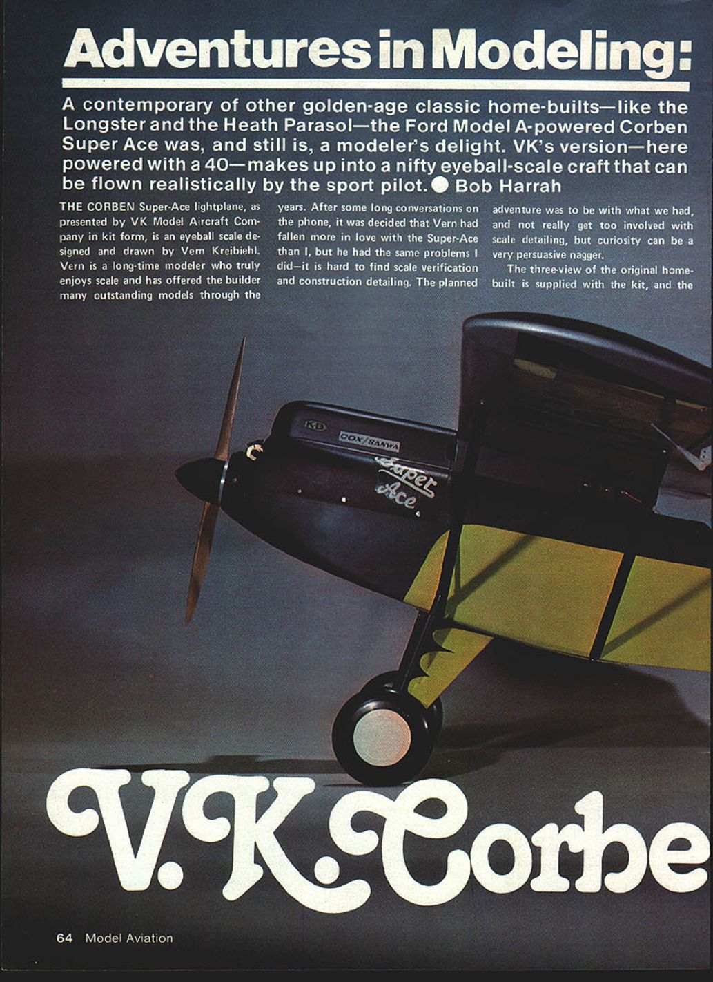
A contemporary of other golden-age classic home-builts—like the Longster and the Heath Parasol—the Ford Model A–powered Corben Super-Ace was, and still is, a modeler’s delight. VK’s version—here powered with a .40—makes up into a nifty eyeball-scale craft that can be flown realistically by the sport pilot.
Research and Scale Details
The Corben Super-Ace lightplane, as presented by VK Model Aircraft Company in kit form, is an eyeball-scale design drawn by Vern Kreibiehl. Vern is a long-time modeler who truly enjoys scale and has offered the builder many outstanding models through the years. After some long conversations on the phone, it was decided that Vern had fallen more in love with the Super-Ace than I had, but he had the same problems I did—it is hard to find scale verification and construction detailing. The planned adventure was to work with what we had and not get too involved with deep scale detailing, but curiosity can be a very persuasive nagger.
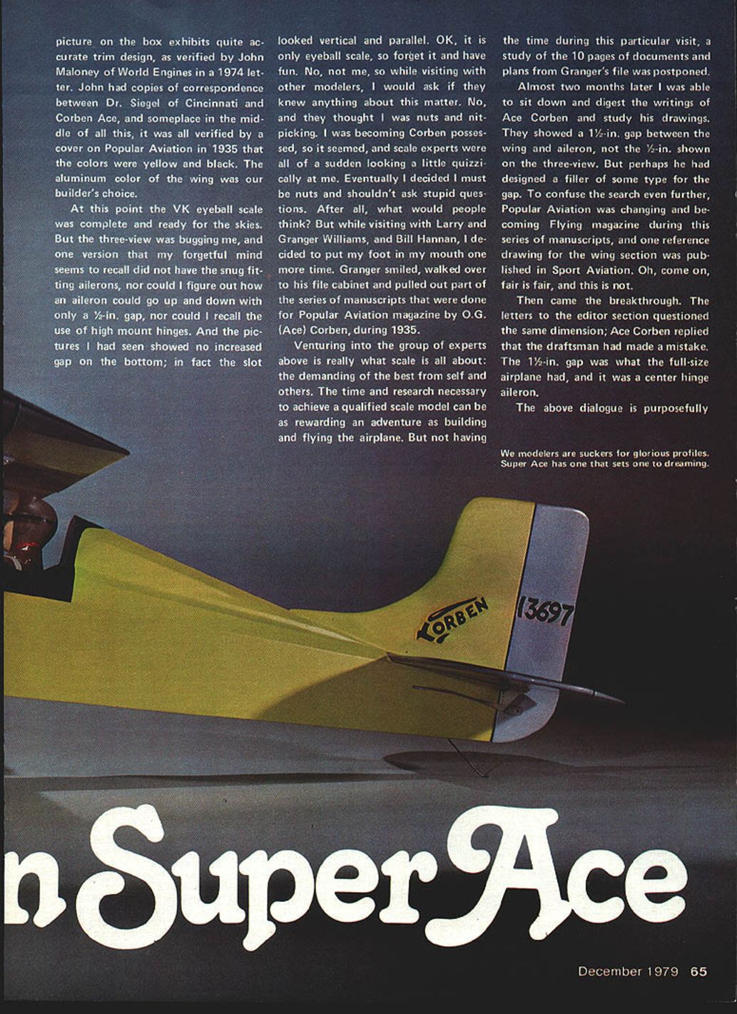
The three-view of the original homebuilt is supplied with the kit, and the picture on the box exhibits quite accurate trim design, as verified by John Maloney of World Engines in a 1974 letter. John had copies of correspondence between Dr. Siegel of Cincinnati and Ace Corben, and a cover on Popular Aviation in 1935 verified that the colors were yellow and black. The aluminum color of the wing was our builder’s choice.
The aileron-gap mystery
At this point the VK eyeball-scale model was complete and ready for the skies. But the three-view was bugging me. One version I recalled did not show snug-fitting ailerons, and I could not figure out how an aileron could go up and down with only a 1/2-in. gap. Pictures I had seen showed no increased gap on the bottom; in fact the slot looked vertical and parallel. OK, it is only eyeball scale, so forget it and have fun. No, not me. While visiting with other modelers, I would ask if they knew anything about this matter. No one did, and they thought I was nuts and nitpicking.
Eventually Granger Williams produced part of the series of manuscripts by O.G. (Ace) Corben published in Popular Aviation during 1935. A later study showed the drawings indicated a 1-1/2-in. gap between wing and aileron, not the 1/2-in. shown on the three-view. To confuse things further, Popular Aviation was changing to Flying magazine during this series, and one reference drawing for the wing section was published in Sport Aviation.
The breakthrough came when a letter to the editor questioned the same dimension; Ace Corben replied that the draftsman had made a mistake. The 1-1/2-in. gap was what the full-size airplane had, and it used a center-hinge aileron.
This episode illustrates what scale modeling is all about: demanding the best from oneself and others. The time and research necessary to achieve a qualified scale model can be as rewarding an adventure as building and flying the airplane.
About Ace Corben
From the golden years of the 1930s—when people ran out of their houses to see a wondrous flying machine overhead—Ace Corben became known for his practical, hands-on approach. He used the Ford Model A as the power source for his Super-Ace, and that connection made the airplane relatable. Though a thousand miles or more separated it from other homebuilts like the Longster, the Corben Super-Ace represented a similar engineering challenge and an advance in practical flying.
Corben took an empirical approach: he built his plane first, flew and modified it, and then published plans. He knew what he wanted and did it. His honest, human articles attracted people who wanted to see and prove the airplane’s performance firsthand. He was ready for all comers and did not hesitate to hop in his plane and give demonstrations. They left believers.
The design is a natural for free-flight scale models (Peanut to Jumbo) and all forms of RC scale. Built from a VK kit, it can be a very stable sport flier with good trainer potential. A quarter-scale .60–.80 version would be great—almost a 7-ft wingspan.
The VK Kit
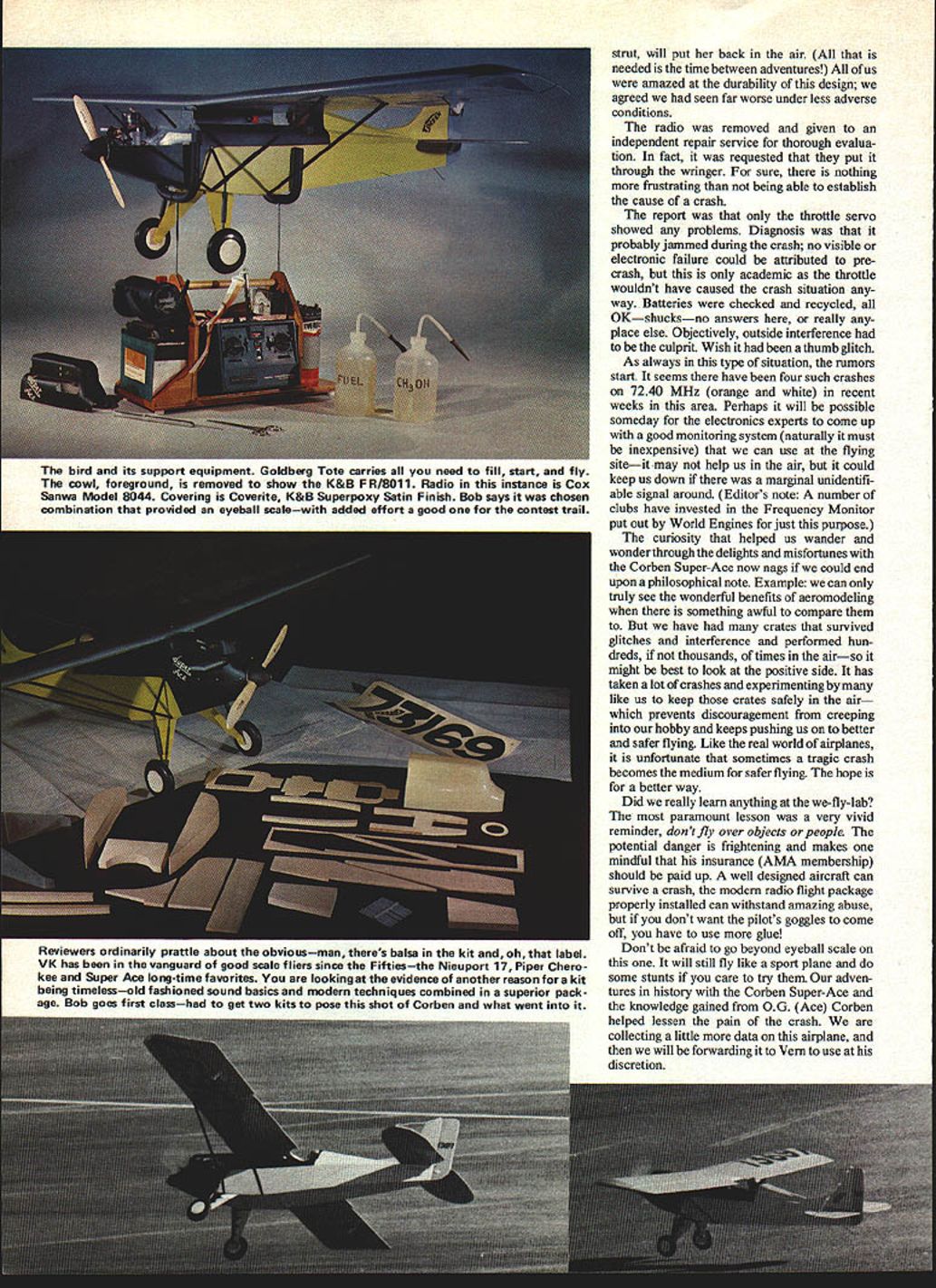
The VK kit is well designed structurally, as the final flight proved. Built as recommended by the manufacturer, covered with Coverite, finished with K&B Superpoxy Satin Finish, controlled with a Cox/Sanwa Model 8044 radio and powered by a K&B .40 FR/8011, this combination offers the average aeromodeler a nifty eyeball-scale sport flier, or with added effort could compete on the trophy trail.
Kit features and recommended gear
- Covering: Coverite (iron-on coverings recommended to expedite build)
- Finish: K&B Superpoxy Satin Finish
- Radio: Cox/Sanwa Model 8044 used in this build
- Engine: K&B .40 FR/8011 used in this build
- Props tried on site: three 10x6 wood props and one 10x6 nylon
- Structures: working wood struts come with the kit; K&S streamlined tubing substituted on this model
- Cowling: vacuum-formed cowling supplied
Construction notes and scale considerations
- Cowling and cooling: An open tunnel on the bottom of the cowling was used on the full-size to direct air to the radiator for the Corben conversion of the Ford A engine. This helps preserve scale points and provides ventilation. The close-fitting cowling supplied was adequate in comfortable weather, but overheating was observed on an 80°F day while operating from hot asphalt.
- Fuel sump suggestion: Fuel overflow and accumulation in the engine and fuel tank area is unavoidable with this installation. We recommend a fuel drain under the tank just in front of the firewall. Alternatively, build a mock-up radiator as shown on the three-view and make it into a fuel sump with drain.
- Tail differences: The home-built plans differ from the kit three-view in the tail section. The full-size vertical stabilizer had a radiused upper leading edge; the rudder top was at right angles to the vertical for just over half the width, then curved to the trailing edge. Corben used bearings mounted on the leading edges of the rudder and elevator tubing, connected with "U" straps to the stabilizer and fin trailing-edge tubing.
- Landing gear: The formed landing gear supplied is for eyeball scale. The original used a triangular strut arrangement hinged at the fuselage, canvas-covered or similarly finished, leaving a gap between the fuselage and the covering material.
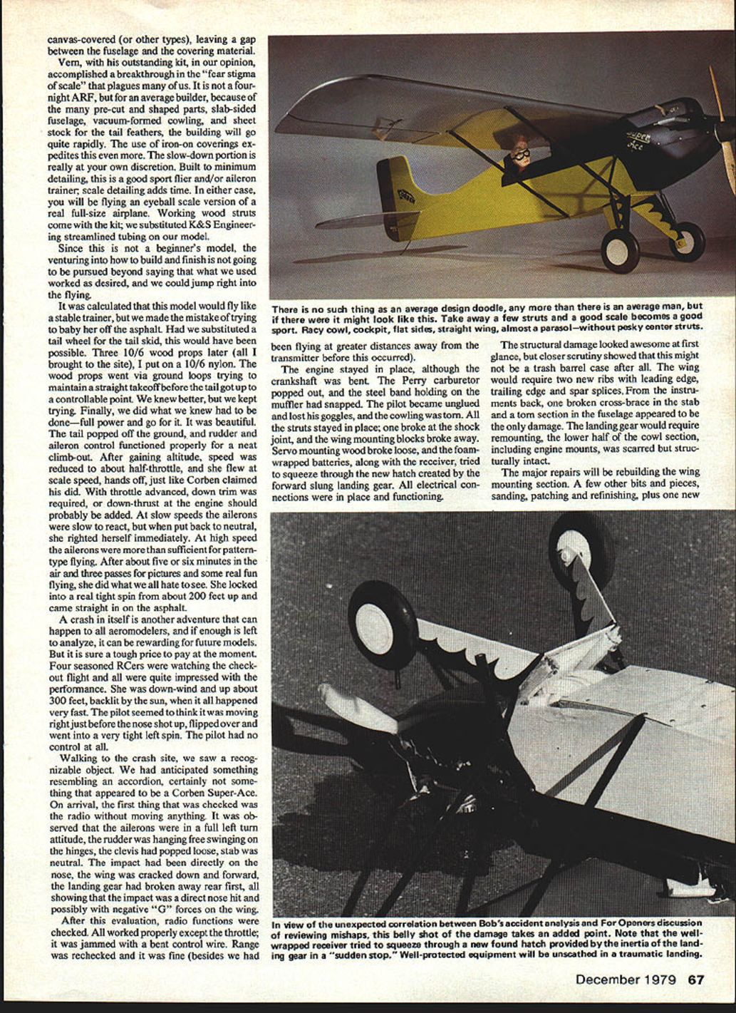
Vern’s kit accomplishes a breakthrough in reducing the “fear stigma of scale.” It is not a four-night ARF, but because many parts are pre-cut and shaped, building will go quite rapidly. Built to minimum detailing it is a good sport flier and/or aileron trainer; scale detailing adds time. Working wood struts come with the kit; we substituted K&S streamlined tubing.
Flight Testing
It was calculated that this model would fly like a stable trainer, but we made the mistake of trying to baby her off the asphalt. Had we substituted a tail wheel for the tail skid, ground handling would have been easier. Three 10x6 wood props later (all I brought to the site), I put on a 10x6 nylon. The wood props led to ground loops during takeoff attempts; the tail eventually got up to a controllable point.
Finally we did what we knew we had to do—full power and go for it. The tail popped off the ground, and rudder and aileron control functioned properly for a neat climb-out. After gaining altitude, speed was reduced to about half-throttle and she flew at scale speed, hands off, just like Corben claimed his did. With throttle advanced, down trim was required; some downthrust at the engine might be advisable. At slow speeds the ailerons were slow to react, but when returned to neutral the model righted itself immediately. At high speed the ailerons were more than sufficient for pattern-type flying.
The crash
After about five or six minutes in the air and three passes for pictures and fun flying, the model locked into a very tight spin from about 200 feet and came straight in onto the asphalt.
Four seasoned RCers were watching the checkout flight. The model had been downwind and up about 300 feet, backlit by the sun, when things happened very fast. The pilot observed a slight right movement just before the nose shot up, flipped over and went into a very tight left spin. The pilot had no control.
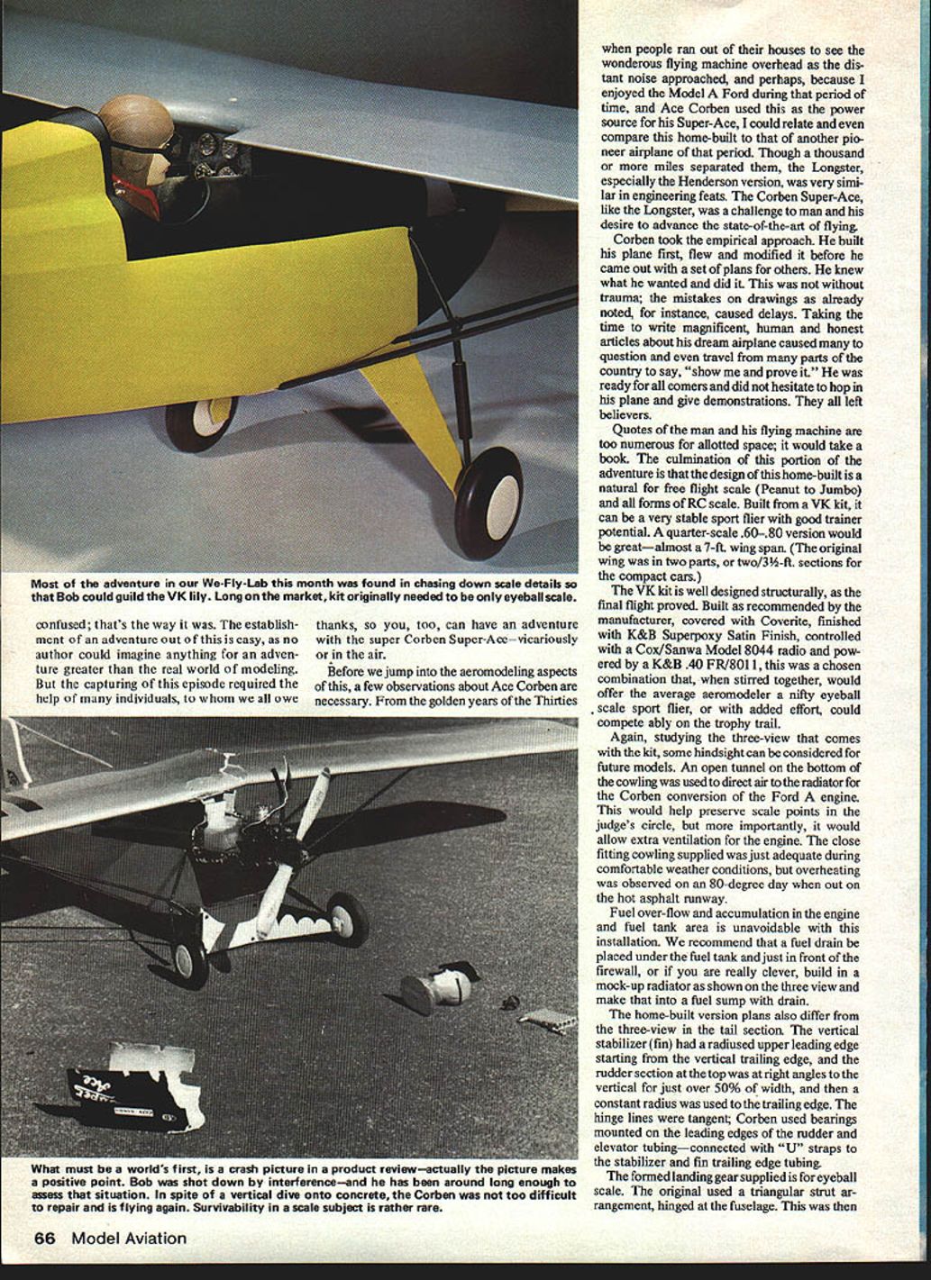
At the crash site the model was recognizably a Corben Super-Ace, but badly damaged. Initial checks without moving anything showed the ailerons in full left attitude, the rudder hanging free and swinging on the hinges because a clevis had popped loose, and the stabilizer neutral. Impact was directly on the nose; the wing was cracked down and forward, and the landing gear had broken away rear first—consistent with a direct nose hit and possible negative-G loading on the wing.
Radio functions were checked: all worked properly except the throttle, which was jammed with a bent control wire. Range checks were fine. The engine remained in place though the crankshaft was bent. The Perry carburetor popped out, the steel muffler band snapped, the cowling was torn, one strut broke at the shock joint, wing mounting blocks broke away, servo mounting wood tore loose, and foam-wrapped batteries and the receiver were pushed forward through a new hatch created by the forward-slung landing gear. All electrical connections were in place and functioning.
Damage Assessment and Repairs
Initial visual damage seemed severe, but closer inspection showed repairable damage:
- Wing: two ribs needed replacement, plus leading-edge, trailing-edge, and spar splices
- Wing mounting section: major repairs required
- Stabilizer: one broken cross-brace in the stab
- Fuselage: torn section aft of instruments
- Landing gear: remounting required and one new strut
- Cowling: lower half scarred but structurally intact; engine mounts generally intact
- Miscellaneous: servo mounting wood replacement, sanding, patching and refinishing
All agreed the design was durable; we had seen far worse results under less adverse conditions.
Radio Investigation
The radio was removed and sent to an independent repair service for thorough evaluation. The report indicated only the throttle servo showed problems. The diagnosis was that it probably jammed during the crash—no visible or electronic failure could be attributed to a pre-crash condition. Batteries were checked and OK. Objectively, outside interference was considered a possible culprit. There had been several crashes on 72.40 MHz (orange and white) in the area in recent weeks.
Clubs have invested in frequency monitors (e.g., from World Engines) to help detect marginal or rogue signals at flying sites. Such monitors may not prevent in-air interference but can help detect problems before takeoff.
Lessons Learned
- Don’t fly over people or objects. The potential danger is frightening and reminds one that insurance (AMA membership) should be current.
- A well-designed model can survive a crash; modern radio flight packages can withstand surprising abuse, but proper installation is critical.
- Consider using a tail wheel instead of a tail skid for better ground handling on paved surfaces.
- Provide adequate engine cooling—use a bottom cowling tunnel or mock radiator/fuel-sump as needed.
- Add a fuel drain or sump to prevent fuel accumulation near the firewall.
- Don’t be afraid to go beyond simple eyeball-scale detailing—the model will still fly like a sport plane and can perform aerobatics if desired.
- Consider monitoring local frequency activity at the flying site.
Conclusion
Our adventures in history with the Corben Super-Ace and the knowledge gained from O.G. (Ace) Corben helped lessen the pain of the crash. We are collecting more data on this airplane and will forward it to Vern Kreibiehl for his use at his discretion. All that is needed now is time between adventures to get her back in the air.
Transcribed from original scans by AI. Minor OCR errors may remain.

