

Aerodynamic Investigations: Part One
Hal deBolt
When you are in the mainstream of model activities, it seems there is never enough time to do what needs to be done to get you to the next action. Along the way you see possibilities you would like to look into, but the needed time flies by.
When you retire from the action, unless the rocking chair beckons, time is available to investigate some of the “if I ever get to it” items. With that thought, I have spent the last two years investigating. Some of my findings were surprising, and all seem worthy to pass on to you.
The objective was to use basic aerodynamics to find methods of improving performance and/or to solve problems. Electrics, my current phase of modeling, make ideal vehicles for research.
Like free flight models, electric-powered Enduro designs must perform over a wide speed range; unlike free flight, excess power is not available to simply blast away. Performance is easily observed; differences are quite apparent in flight.
Unfortunately, I do not have sophisticated wind tunnels, but a lot can be learned by “comparative flying.” Successive flights can be compared, even using different configurations, and if many flights are made, the results have to be for real.
Part one of a two-part article, where the author uses an electric Enduro to solve aerodynamic problems and improve performance.
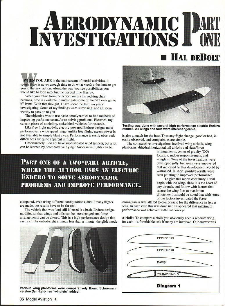
The vehicle that was (and still is) used is a basic Enduro design, modified so that wings and tails can be interchanged and force arrangements can be altered. This is a high-performance design that easily climbs out of sight in much less than a minute; the glide mode is also a match for the best. Thus any flight change, good or bad, is easily observed, and comparisons are simple.
The comparative investigations involved:
- wing airfoils
- wing planforms
- dihedral
- horizontal tail airfoils and sizes/force arrangements
- center of gravity (CG) location
- rudder responsiveness
- winglets
None of the investigations were developed fully, but areas were uncovered that indicated further development would be warranted. In short, positive results were seen pointing to improved performance.
To give this report continuity, I will begin with the wing, since it is the heart of any aircraft, and follow with factors that assure the wing flies at maximum efficiency. It should be noted that with some of the factors investigated the force arrangement was altered to compensate for the difference in forces seen. In each case this was done until it appeared that maximum performance was achieved with that concept.
Airfoils
To compare airfoils you obviously need a separate wing for each—a formidable task if many are involved. Our answer was to choose four proven airfoils which would indicate what to expect. For anything similar in nature I started with Eppler 193, widely used on electric-powered Enduros. Performance was excellent and formed a basis for comparison. It did appear a bit touchy longitudinally; stability could be controlled by judicious adjustments in the force arrangement.
The second airfoil investigated was Eppler 176. The major difference between the two airfoils is 176 is about 20% thinner than the 193 wing, creating less drag. A thinner airfoil should result in less drag and higher flying speed; the question was whether higher flying speed would allow a thinner section to equal the lift of a thicker one and whether the rate of climb would be greater. Comparative flying indicated higher flying speed gave increased rate of climb. Higher speed proved a distinct advantage in thermal hunting; windy conditions slowed down the match for 193’s flying speed, and the higher rate of sink was obvious. As speed increased, the liking for 176 grew, and its sink rate became comparable. Bottom line: 176 needs to fly faster.
Many modeling years and numerous types of models have found Davis airfoils outstanding, providing excellent lift, stability, and low drag. I had a strong desire to compare the Eppler and Davis sections; however, Davis airfoils are familiar with undercamber and associated drag that could be expected. Fortunately I found a flat-bottom version in John Malkin’s fine airfoil book. The Davis section was identical in thickness to the Eppler 193.
Comparative flying immediately showed Davis 193 wings could be readily interchanged; no adjustments were required. I found the Davis tolerant of CG changes that affected the Eppler; its stability remained intact with a farther-aft CG. An aft CG that allowed use of tail lift equates total lift; added tail lift is also an asset in controlling power. Over the long haul, comparative flying with the three airfoils showed the Davis did seem to have an advantage under normal flying conditions. However, the edge would go to the Eppler 176 in windy weather.
The last airfoil tested was one of those “wonder what would happen” investigations. Theory tells us we can expect more lift from an airfoil that features undercamber. We would like more lift; however, the additional drag would be a detriment to the rate of climb—an equally important consideration.
The question became how I could gain the added undercamber lift without increasing the drag over a flat-bottom section. A clue came from the FF fraternity, where a fundamental factor has been the use of very thin undercambered airfoils.
I needed to determine whether the drag of a thin undercambered airfoil would be equal to that of a normal flat-bottom section and whether there would be an increase in lift. To evaluate this thinking I chose to reduce the normal 11% thickness of a Davis #5 airfoil to 7%.
(As a sidelight, you can see that when a 10-inch chord has a thickness less than 3/16 in., there could be a strength problem. I am happy to report that my particular stressed-skin structure has proven to be most adequate in a complete range of flying conditions.)
Comparative flying of the thin undercambered section immediately opened my eyes! Simply interchanging this wing with the others produced a vicious stalling tendency—a strong indication that more lift was being produced. To obtain satisfactory performance, a radical change had to be made in the force arrangement.
Increasing tail lift removed the power-on stall, but resulted in a nose-down attitude in the glide mode. It was obvious that this section was much more sensitive to speed changes. The final change that produced satisfactory overall performance was to move the CG back to a proper position relative to the new mean centerline, which created an excellent glide mode without affecting the power mode.
So how does this thin undercambered section compare to the other airfoils? The gliding and power-on speeds and the rate of climb are comparable to the Eppler 193 and Davis airfoils. However, the Eppler 176 is quicker in all respects. The rate of sink in average conditions is also similar.
A pronounced asset is quite apparent: the undercambered airfoil does respond to light lift more readily and better than any of the others. This could be due to a combination of all the elements involved in this configuration. However, it should be noted that it is this airfoil that allows the change in the elements.
Summary
After all this effort, one factor stands out: considering that performance differences were seen between some of the airfoils, the general performance of any of them would be acceptable for Enduro flying. One of the differences seen might suit some particular need; the Eppler 176 for speed, the thin undercambered section for light lift, etc. Sorry, but no great magic was found to astound you!
Dihedral
We see numerous gliders and exotic electrics apparently flying well with little or no dihedral. The objective is to regain the lift lost when normal dihedral is removed while maintaining lateral stability. Various angles are used. The only negative factor is the apparent need to use ailerons for directional control.
We might ask whether the additional weight and complexity of the ailerons outweigh any gain in lift. A second question could be whether the use of dihedral for adequate yaw control when using rudder can be alleviated. My experience indicated that some dihedral effect was an asset for lateral stability and creating flatter turns. I also found that a minimum of dihedral was sufficient.
My investigation included a minimum amount of dihedral, comparing polyhedral effect to straight dihedral and obtaining suitable yaw control with rudder. For a comparison base, we used classic polyhedral.
Even with the low angles used, there proved to be no shortage of stability. However, rudder control was very soft, especially at the low speeds typical of gliders and electrics. Another wing with low, straight dihedral yielded similar yaw-control results. At least for RC craft, dihedral angles can be kept to a minimum with no adverse results. Polyhedral appeared to provide no benefit; hence its complexity could be eliminated.
Yaw control
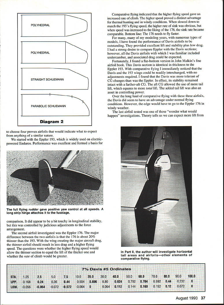
A rudder/fin of typical size and location for models of this type was initially used. Under power and in the glide mode, this proved usable at altitude, although the response time was slower than one might like. At minimum flight speeds, as might be seen on a landing approach, I often wondered if the rudder had quit working! Not the best situation, by far.
The cure was to use a full flying rudder-fin pivoted at the 1/3-chord point, very much like what was used on WWII pursuit planes. On the initial powered launch with this arrangement, I was shocked when a slight yaw correction was desired—a normal application of rudder—yielded the model a complete 90°! Directional control was used with kid gloves for the rest of that flight.
For the next flight, the normal amount of rudder deflection was cut in half. Since then we have had nothing but positive, instantaneous yaw control under all circumstances. Would this concept be adequate for flat wings in place of ailerons? It could be assumed that yaw control would be adequate, but would the rudder action raise a dropped wing as ailerons do? So far I just haven’t had an opportunity to investigate.
Wing planforms
The classic FF-style wing planform, especially when polyhedral is used, is a long, straight center panel with tapered tips. Such a shape has always provided excellent performance, so it was the basis for our comparisons.
Some time back, there was much ado in the media, plus positive reports from modelers, expounding the virtues of the Schuemann wing planform. I felt this was worthy of attention, so a straight-dihedral wing using the Schuemann planform verbatim was produced and flown.
The first indication of a difference was the need to move the CG back. The swept-back tips obviously moved the center of lift rearward. After the required trim change, numerous comparative flights were made with no outstanding difference. However, there did appear to be a slight increase in penetration and a questionable increase in lift—no worse than the classic wing, for sure, and a possible plus factor.
Another planform that time tells us should be the acme of shapes is the elliptical outline. The Schuemann planform has a leading edge with sharp changes in direction. Fundamental drag factors dictate that sharp contour changes are a no-no in all respects.
That raised another question: could the Schuemann planform be improved by using a parabolic curve to remove the sharp breaks? It seemed to be worth a try, so we took the Schuemann layout and developed a parabolic curve that intersected all the Schuemann parameter points. If nothing else, this produced a “pretty to look at” birdlike wing.
It would be great to be able to say that comparative flights were sensational, but the real story is that you have to look closely to observe any real difference. I can say that wings were similar to those seen with the true Schuemann shape; however, this time they were more pronounced. The parabolic planform appears to be the most efficient of the lot, even if only in a small way.
The canard is a final planform worthy of mention, because it might solve a nasty problem such as a tail-heavy design with no other suitable cure. One consideration is how to get the center of wing lift far enough back for balance purposes. Using the KISS (Keep It Simple, Stupid) principle for my initial effort, I used a typical FF-style polyhedral wing. Normally my planform uses equal taper for the tip leading and trailing edges; for the canard, I put all the taper in the leading edge—swept the tips back, so to speak.
I first flew this wing on the normal configuration. As with the initial Schuemann flights, the center of lift was obviously much farther back than normal. After the required CG trim change, this wing compared very closely to our classic wing. It appears to be possible to cure a tail-heavy condition by sweeping the wing tips aft.
To conclude our wing investigations, I believe the low straight-dihedral parabolic Schuemann planform with a thin airfoil had the greatest efficiency. The results of my comparative flying of wing planforms would be very similar to those seen with airfoils. There probably is no planform that is vastly superior, provided you do not stray far from the established path.
"Aerodynamic Investigations" will conclude in a second segment, which will describe extensive investigations into horizontal tails, force arrangements, and winglets.
Transcribed from original scans by AI. Minor OCR errors may remain.

