

AERODYNAMIC INVESTIGATIONS PART TWO
Hal deBolt
In part one of this report we investigated wing design parameters. In part two we will study horizontal tails, winglets, and force arrangements.
HORIZONTAL TAILS
When the thin, undercambered Davis wing airfoil required a marked increase in tail lift to create a proper proportion for stable flight, the door was opened for an investigation into horizontal tails.
Lift can be adjusted using any of three factors:
- Area
- Airfoil
- Angle of attack
Our standard stabilizer's area is 25% of the wing area and has a 6% flat-bottom airfoil. This proved usable with all of the wings and other changes investigated. However, an investigation of all factors seemed worthwhile, so a program of that nature was initiated, using the "problem" thin Davis airfoil for the wing.
Satisfactory flights were first obtained with this wing by simply increasing the angle of attack of the standard stabilizer 2°, which effectively created a proper proportion between the wing and tail lift.
The next try involved a similar stabilizer with the airfoil increased to 8% thickness. As expected with this change, the angle of attack had to be reduced to obtain satisfactory flight. It proved to be just another way to adjust the lift proportion, as comparative flying indicated no change in performance.
At that point a larger stab was produced using the 8% airfoil, with an area increase to 30%. Adjusting the lift proportion with this one required a further reduction in the angle of attack. Actually, we returned to the setting that created the original problem with the 6%-thick, 25%-area stab. The conclusion was that the needed lift could be created by the airfoil, the angle of attack, or by increasing area.
Flights with the 30% stab were not positive; the rate of climb was reduced a bit, and the glide was slower. There was a reduction in sink rate, which would indicate a plus factor for dead-air flying, but that was about it.
Another investigation was an attempt to use the additional lift generated by the thin, undercambered Davis airfoil. Could a gain be achieved by trading the increased airfoil lift for a decrease in area? Another stabilizer was built using the 7% Davis #5 airfoil and 20% area. This one created the most lift of all. The angle of attack required for satisfactory flight was much less than any of the others.
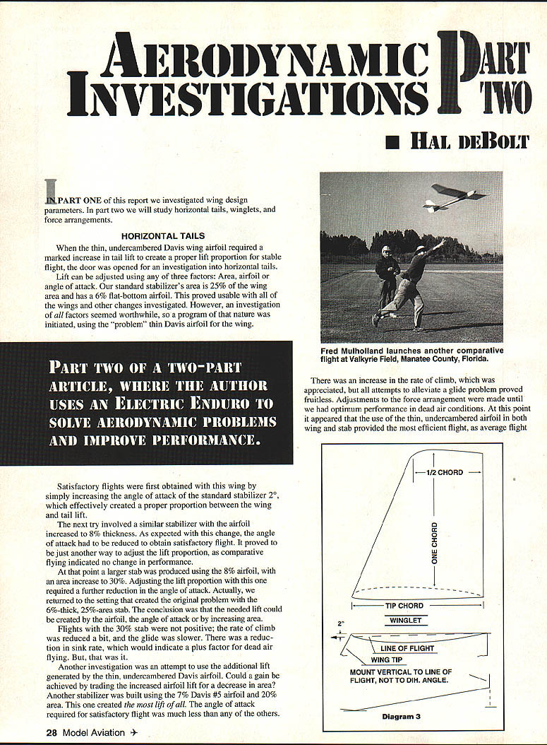
There was an increase in the rate of climb, which was appreciated, but all attempts to alleviate a glide problem proved fruitless. Adjustments to the force arrangement were made until we had optimum performance in dead-air conditions. At this point it appeared that the use of the thin, undercambered airfoil in both wing and stab provided the most efficient flight.
At times of stronger thermals the combination behaved as desired and the model could be flown within the boundaries of thermal flight. However, in small thermals the best it could do was fly through. At times the model would enter a thermal and an abrupt stall would result. It would continue through several oscillations before settling down again, and naturally altitude was lost in the process.
The conclusion was that the wing encountered the thermal effect before the tail did; the tail force was not strong enough to control the disruption. Something similar has been seen with other arrangements. Any suggestions would be appreciated.
The final horizontal tail investigation involved a stab of 18% area with an 8% flat-bottom airfoil interchanged with the standard tail; no flight difference was seen. The conclusion was that the lift of both stabilizers was similar: the smaller tail produced lift to match the larger because its airfoil was thicker.
Final thought: a larger tail could have an advantage at low speeds, as airfoil lift is affected by speed and area. Juggling the three lift factors for tails is a reasonable concept and can produce similar performance. Considering flight parameters, it does appear the standard stabilizer configuration (6% airfoil, 25% stab area) did the desired work very effectively; other configurations offered distinct advantages in particular conditions.
WINGLETS
Even a casual observer could be impressed by Witcomb's NASA experiments with winglets. Burt Rutan's application of Witcomb's findings is also impressive. Lately we even see winglets on various commercial jets, including 747s. If those guys found something good, the small effort required to investigate them seemed worthwhile.
To date we have only taken one KISS-style (Keep It Simple, Stupid) look at them, but the results say "look again, there is some good here!" Most of us can point to some past experience with tip plates of one sort or another. There have been very few instances where any good can be claimed for them. The important thought is: winglets are not the familiar tip plates. Instead, they are more complex and create more actions and forces.
Since this is an investigative report, we will not dig into winglet theory; a simple description of their actions should do. First, it is basic that wing efficiency suffers because lift is lost while drag is increased when the higher pressure on the wing's lower surface travels around the wingtip into the lower pressure on the top side. Tip plates were a simple attempt to alleviate this negative factor, but they usually failed because they added excessive drag.
The winglet theory is supposed to be superior, through the use of basic aerodynamics and the creation of a new positive force. The negative tip factors can be reduced by using a minimum tip chord and a high aspect ratio. However, used to the necessary extreme, these factors lead to other negative effects, which can negate any gain.
Witcomb found that winglets could effectively increase the aspect ratio without actually doing so. The winglets become part of the wing span, so if the winglets' tip chord is less than that of the actual wingtip, the tips are in effect less narrow, plus there is less pressure movement and drag. Additional help is also provided by the fact that the winglets really do act like wings.
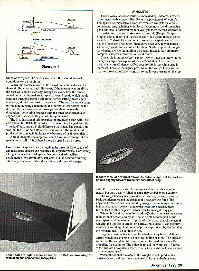
To gain a positive force from the winglets, they have a definite airfoil, which has an angle of attack to the line of flight. The angle is set so that the winglets' lift force is aimed forward (at a model's propeller, for example). The object is to add the winglets' lift force to the aircraft's propulsion force, to offset the additional drag created by the winglet itself.
Witcomb felt that the total of the winglet effects produced a positive factor, and thus they were useful; Rutan's findings were apparent proof of this. Specific parameters must be followed to assure success, but they are not complicated.
We have often been led astray by some "wonder" from the full-scale world which, after much effort, has proven of little use for our models. Experience has taught us to try these things in as simple a way as possible, then go from there. With this in mind, we had a usable wing on our canard and we knew what its performance was with tip plates; it was usable on our normal-configuration design.
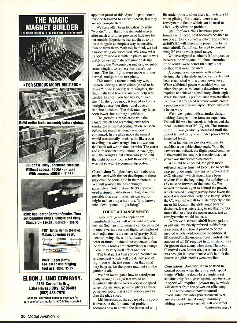
Using the Witcomb parameters, we made some winglets to replace this wing's tip plates. The first flights were made with our normal-configuration test plane.
This model's normal tendency was to "search" during a steep climb (it had to be flown "up the ladder"); with winglets, the flight path held true and no pilot help was needed. In short: I like that! In the glide mode it tended to hold a straight course, and directional control remained positive. The sink rate may have been lower, but nothing significant.
The greatest surprise came with the canard, which had searching tendencies similar to the normal configuration. As seen before, the search tendency was now eliminated. In the glide mode the canard would occasionally "rock" a bit, like a boat traveling in a wave trough, but this was not the Dutch roll we are familiar with. The cause and cure remained mysterious. Amazingly, with the winglets that action was gone, and the flight became rock solid. Remember, this was not so with the common tip plates.
Conclusion: Winglets have some obvious merits, and with further development there may even be some gold in them there hills! Our KISS approach used a simple flat-bottom airfoil; it seems possible that a semi-symmetrical section might reduce drag a bit more. Who knows what development might bring?
FORCE ARRANGEMENTS
Force arrangements depict how longitudinal forces will work with a given design. Such an arrangement can be adjusted to create various sorts of flight. Examples of such adjustments are:
- Center of gravity (CG) location
- Wing lift
- Tail lift
- Mean lift
- Point of thrust
It should be understood that when one aerodynamic factor is changed it may very well affect another. The best part is that you can produce an arrangement which will create any sort of flight you wish; just remember that what may be great for the goose may not suit the gander at all.
We first investigated how to aerodynamically arrange a design that would be longitudinally stable over a very wide speed range. For instance, powered gliders have a power-on speed that is considerably greater than the glide speed.
Lift increases as the square of any speed increase, so the fundamental problem becomes how to control the increased wing lift under power, when there is much less lift when gliding. Fortunately there is an aerodynamic factor which can be used to effectively solve the problem.
The lift of all airfoils increases proportionally with speed, so it becomes possible to use one airfoil to control another. The control airfoil's lift will increase in proportion to the main airfoil. Tail lift can be used to control wing lift over a wide speed range.
We investigated a suitable lift proportion between the wing and tail, then determined if the results were better than any other method that might be used.
A comparison was made with a basic design, where the glide and power modes had been established with a given power level. When additional power was added with no other changes, considerable downthrust was required to achieve a satisfactory climb angle. While the model's performance was excellent, the idea that any weight increase would create a problem was frowned upon. There had to be a better way.
We investigated with a similar design, making changes to the force arrangement. The tail lift was increased, which moved the mean coefficient of lift (Cm) aft. The amount of tail lift was gradually increased until the model tended to fly level under power when launched.
After launch, the elevator was used to establish a desirable climb angle. With the elevator neutralized, the flight would continue at the established angle. It was obvious that power was under complete control.
As might be expected, the glide mode suffered, and up trim had to be used to obtain a proper glide angle. The answer proved to be a CG change—which should have been obvious from the beginning. For stability the CG must be forward of the mean CL. We moved the mean CL aft to control the power, which created a longer gravity-force lever; the model was now effectively nose heavy. When the CG was moved aft to relate properly to the mean lift location, the glide angle became desirable. It was interesting to see that the CG move did not affect the power mode, just as aerodynamics would indicate.
When we discussed airfoil investigations in Part One, we briefly referred to force arrangement and how it proved to be the method which would control the additional lift created by the undercambered airfoil. The amount of tail lift required in this instance was far greater than at any other time. The mean Cm moved even further aft, yet when the CG was brought into compliance with it, both the power and glide modes were excellent.
Conclusion: Downthrust can be used to control power when there is a wide speed range. While the downthrust angle is set satisfactorily for a given speed, any increase in speed will require a greater angle, which will detract from the power-on efficiency.
The aerodynamic power control investigated provides power control over any reasonable speed range; normally, adding more power (speed) will not affect neutral stability—the flight path will be in whatever direction the plane is pointed. Obviously that makes it most suitable for RC aircraft. This arrangement also adds to efficiency beyond the gain from lack of downthrust. With the additional tail lift required, the model's total lift is increased.
While these investigations were made with electric-powered Enduro-style RC models, most of the factors would also apply to other model types. This is especially true for the neutral-stability force arrangement, where we actually drew from previous Pattern design experience. In Pattern, effective speed control is a must; evaluators always say that a good Pattern design is one whose line of flight is where the pilot points it. In short, the findings are applicable to all model designs.
What we have reported represents two years of judicious investigations. I hope that the findings have proven interesting, and that they may be of some value to you. Further, I hope this work may inspire your own investigations. Better flying can be had through aerodynamics!
Transcribed from original scans by AI. Minor OCR errors may remain.

