
Aeronca K
Rolfe Gregory
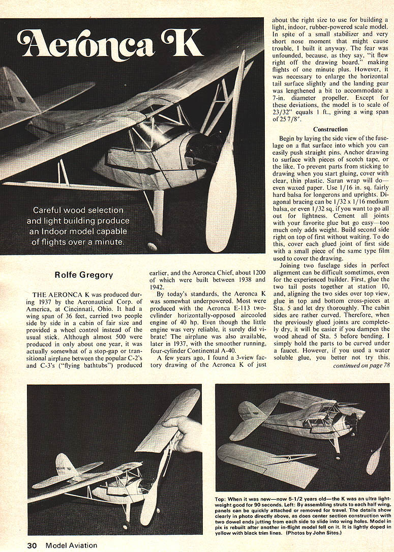
THE AERONCA K was produced during 1937 by the Aeronca Corp. of America, at Cincinnati, Ohio. It had a wing span of 36 feet, carried two people side by side in a cabin of fair size and provided a wheel control instead of the usual stick. Although almost 500 were produced in only about one year, it was actually somewhat of a stop-gap or transitional airplane between the popular C-2's and C-3's ("flying bathtubs") produced earlier, and the Aeronca Chief, about 1200 of which were built between 1938 and 1942.
By today's standards, the Aeronca K was somewhat underpowered. Most were produced with the Aeronca E-113 two-cylinder horizontally-opposed aircooled engine of 40 hp. Even though the little engine was very reliable, it surely did vibrate! The airplane was also available, later in 1937, with the smoother running, four-cylinder Continental A-40.
A few years ago, I found a 3-view factory drawing of the Aeronca K of just about the right size to use for building a light, indoor, rubber-powered scale model. In spite of a small stabilizer and very short nose moment that might cause trouble, I built it anyway. The fear was unfounded, because, as they say, "it flew right off the drawing board," making flights of one minute plus. However, it was necessary to enlarge the horizontal tail surface slightly and the landing gear was lengthened a bit to accommodate a 7-in. diameter propeller. Except for these deviations, the model is to scale of 23/32" equals 1 ft., giving a wing span of 25 7/8".
Construction
Begin by laying the side view of the fuselage on a flat surface into which you can easily push straight pins. Anchor drawing to surface with pieces of scotch tape, or the like. To prevent parts from sticking to drawing when you start gluing, cover with clear, thin plastic. Saran wrap will do—even waxed paper. Use 1/16 in. sq. fairly hard balsa for longerons and uprights. Diagonal bracing can be 1/32 x 1/16 medium balsa, or even 1/32 sq. if you want to go all out for lightness. Cement all joints with your favorite glue but go easy—too much only adds weight. Build second side right on top of first without waiting. To do this, cover each glued joint of first side with a small piece of the same type film used to cover the drawing.
Joining two fuselage sides in perfect alignment can be difficult sometimes, even for the experienced builder. First, glue the two tail posts together at station 10, and, aligning the two sides over top view, glue in top and bottom cross-pieces at Sta. 5 and let dry thoroughly. The cabin sides are rather curved. Therefore, when the previously glued joints are completely dry, it will be easier if you dampen the wood ahead of Sta. 5 before bending. I simply hold the parts to be curved under a faucet. However, if you used a water soluble glue, you better not try this.
While damp, place structure over top view and bend the two sides to match the drawing. Block or pin structure in place and add remaining cross pieces of 1/16 sq. Cut Sta. 2 former and instrument panel (Sta. 3) from 1/16 sheet and glue in place. The space between Sta. 2 & 3 is covered with 1/32 sheet, preferably 1/64 if you have it. The wood grain should run in a fore-and-aft direction. Add remaining diagonal braces, top and bottom.
Carve upper nose piece from a soft balsa block of about 3/4 x 1 x 1-1/2 and hollow out to about 3/32 thick. Don't try initially to carve to exact shape—final shaping is done after everything is glued together and dry. In the same manner, carve and hollow the lower piece from a block approx. 5/8 x 3/4 x 1-1/4 and glue to the bottom of upper piece. Cut out 3/4 diameter discs from 1/16 balsa with 3/8 sq. hole in center of each to accommodate a Williams Bros. plastic nose bushing bearing, and laminate together, alternating grain direction. Join the upper nose piece and then bolt nose piece in front of fuselage. Carefully sand parts to final outline shape of the drawing. Make windshield V-brace and two side bra ces between Sta. 3 & 4 of 1/16 sq. and sand to round shape. Add other V-braces of 1/32 sq. in cabin top between Sta. 4 & 5 and the landing gear support piece of 1/16 balsa, 3/4 x 1/4, in bottom of fuselage, centered between cross braces, Sta. 3 & 4. Cut triangular pieces 7/16 x 7/16 from 1/32 flat with 1/8 hole in center of each, flat and glue in place as shown in small perspective view. The 1/8 holes receive the ends of the 1/16 round struts and allow flexing of the gear for landing. You can skip this work if you build the optional gear used on later K models and shown in side view in broken lines of the drawing.
Bend wing strut attach fittings from .015 music wire and attach to fuselage bottom, Sta. 4. Make two motor peg attach supports from 1/32 hard balsa and glue in place one on each side at Sta. 4. Add tail skid shaped from 1/16 balsa. The landing gear is a single piece of 1/32 music wire bent to shape and glued to the bottom of the fuselage. Make each fairing from two pieces of 1/32 flat glued together; fairing to fuselage—leave free to flex. Wheels are 1 in. balsa, 3/8 wide, the lightest you can find. Glue a washer on each side as a bearing, hollow opposite side about 1/8 deep, and glue a washer on the bottom for the other bearing. Mount wheels and retain with another washer held by a 1/16 music wire with a tiny drop of epoxy. Cover whole with balsa hub cap painted yellow.
Build two wing panels directly over the drawing, one left and one right. Experienced builders may wish to use the sliced rib technique rather than solid ribs. Even the less experienced may wish to try his hand at this one — it flies well and is forgiving in flight. Try the method to save weight because it really isn't too difficult.
If using solid ribs, make a template to shape and cut 20 ribs from 1/32 flat, medium to light weight balsa, preferably "C" grain. This has a flaky, mother-of-pearl appearance on the surface and is resistant to bending.
If you use sliced ribs, you will still need six solid ribs, one for the root rib of each panel and four for the center section. Then use upper curve of template and slice 14 pieces from light 1/16 flat, each 1/16 deep. You only need tops—bottoms are 14 pieces of 1/16 sq., exactly 2 3/4 inches long.
The front spar is 1/32 x 3/16 for the solid rib arrangement and 1/32 x 5/32 for the sliced. The rear spar is 1/32 x 5/32 for the solid, and 1/32 x 1/8 for the sliced. Use C-grain wood for spars. Select strong, straight 1/16 sq. for leading edges and likewise for trailing edges, except the rear 1/16 x 1/8, sanded to a tapered cross section, either before or after assembly. Make wing tips by first soaking three strips of 1/32 x 1/16 balsa in hot water for a few minutes, adding a ribbon of white glue along each, and bending all three while wet around a form having the wing tip shape. The secret here, I find, is to anchor one of the three joined strips to the form, as with a strip of masking tape, and, with strips between your fingers, pull and guide them around form and then anchor that end. It takes some practice.
For demountable wings, cement short 1/16 diam. aluminum tubes on top of the wing spars, first cutting holes through root rib so the ends fit exactly flush with the outer surface. Incline root ribs slightly for dihedral of 3 degrees. Add three small triangle pieces of 1/32 at wing strut attach points.
Build the center section (over fuselage top view) composed of leading edge, trailing edge and rear spar, all 2 3/4 inches long, plus four 1/32 ribs, a skylight rear piece 1/32 x 11/32 x 1-5/16, and two short front spars each 1/16 x 13/64 deep x 1-1/16. Cement the whole assembly to top of fuselage, aligning it very carefully. Make a windshield pattern from paper by cut and try. When it fits, use to cut windshield from very thin clear plastic, and glue around edges (white glue usually works) and hold in place with tape or pins until dry.
The stabilizer is all 1/16 sq. except for the six 1/32 x 1/16 ribs and tips laminated of three 1/32 x 1/16 strips as for the wing tips. Likewise the fin and rudder assembly is all 1/16 sq. except for the 1/32 x 1/16 ribs and the laminated outline. Three lengths of thin copper wire pushed through pin holes in the two spars and well glued to the ribs serve as bendable hinges for rudder adjustment.
Make two front wing struts 3/32 x 7/32 x 6-3/8 sanded to streamline cross-section, and two rear 1/8 x 5/32 x 6-1/2. Trim one end of rear to fit against front and glue together to form a V exactly 1-1/8 between open ends. The jury strut assembly has front upright 1/8 x 5/32 x 1-7/32 with other two pieces cut to fit from 1/16 round. Bend attach hooks from .015 music wire and bind with thread and glue to lower end of front struts. Paint strut assemblies yellow.
Cover wings (but see next paragraph first), stabilizer, rudder, fin and fuselage with yellow tissue, but not the center section until wire wing supports have been made, mounted and glued. Make the three keel supports from 1/32 wire and insert ends into aluminum tubes in wings, sliding up to the dihedral bend. Cut notches in root ribs above spars and lower support wires, with wing panels attached, onto tops of spars and glue securely, after making sure wings and fuselage are in perfect alignment. Now plug the notches in the root ribs with scrap 1/32, cover the center section, glue stabilizer on top of fuselage and finally mount fin and rudder assembly.
License numbers may be cut from black tissue but, before covering, I prefer to lay the tissue over drawing of part to be covered and trace outlines of numbers using black India ink, straight edge and drafting pen. I fill in outlines with ink, and then cover part. Door outlines and fuselage strips can be made in similar fashion as well as cabin window outlines. For windows, cut out tissue within each window outline using a sharp blade, then cover holes with a strip of cellophane glued to the inner surface of the fuselage side.
All covered parts may be lightly sprayed with water to shrink the tissue but pin down wings and tail parts until dry to prevent warping. Doping isn't necessary for indoor flying but one or two coats of thinned, well-plasticized dope will seal out moisture and prevent the tissue from sagging from high humidity. I use "Micro-Coat" available from Micro-X, 5200 Seven Pines Dr., Lorain, Ohio, 44053, as well as other indoor model supplies. Many hard to find goodies are obtainable from Oldtimer Models, 7454 W. Thurston Circle, Milwaukee, Wisc., 53218. On the West Coast, try Peck-Polymers, P.O. Box 2498, La Mesa, Calif., 92041, or Marlow Engineering, 2650 Vineland, N. Hollywood, Calif., 91605.
Make a dummy engine from balsas, pins, etc., and add any other details you may wish including fuel cap and gauge, aileron and elevator and cowl dividing line stripes, door handles, etc. Carve a balsa propeller from a block as shown, or use a 7" plastic. If you've built light, an 18" to 20" loop of 1/8" Pirelli should fly it nicely. If taut heavy (perish the thought!) add clay to nose. If you don't want an experimental airplane, replace the "X" with "NC".
The model in the pictures is now four years old and shows the signs of wear. Wings and tail were originally covered with "Microlite," a very thin polycarbonate film used in making electrical capacitors, available from Micro-X, and the fuselage was covered with dyed condenser paper. Original weight was less than 1/2 oz., giving flying times of 1-1/2 minutes, plus. I later painted wings and tail with yellow vinyl ink but it caused wrinkles, added weight and cut flight time. Unless you just wish to experiment, I suggest Japanese tissue for the whole model.
Transcribed from original scans by AI. Minor OCR errors may remain.

