
Aeronca K
Overview
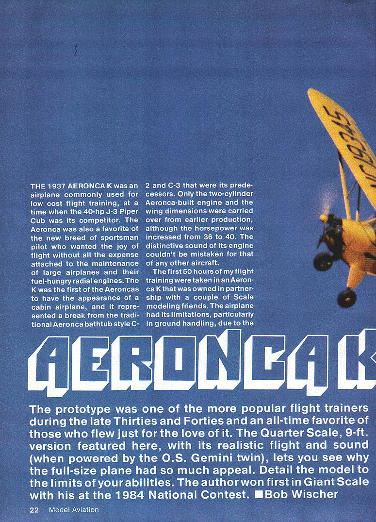
The 1937 Aeronca K was commonly used for low-cost flight training, competing with the 40-hp J-3 Piper Cub. It was also a favorite of the new breed of sportsman pilots who wanted the joy of flight without the expense of larger airplanes and fuel-hungry radial engines. The K was the first Aeronca to have the appearance of a cabin airplane, a break from the bathtub-style C-2 and C-3 predecessors. Only the two-cylinder Aeronca-built engine and the wing dimensions were carried over from earlier production, although horsepower was increased from 36 to 40. The distinctive sound of its engine was unmistakable.
The first 50 hours of my flight training were taken in an Aeronca K that was owned in partnership with a couple of scale-modeling friends. The airplane had its limitations, particularly in ground handling, due to the absence of wheel brakes. This wasn't all bad, though, as it taught the rudiments of handling an airplane more like a sailboat than a car. Engine reliability wasn't a problem. Sketches of the airplane's structure were made in 1941, but construction of the 1/4-scale, 9-ft.-span model was delayed for 41 years.
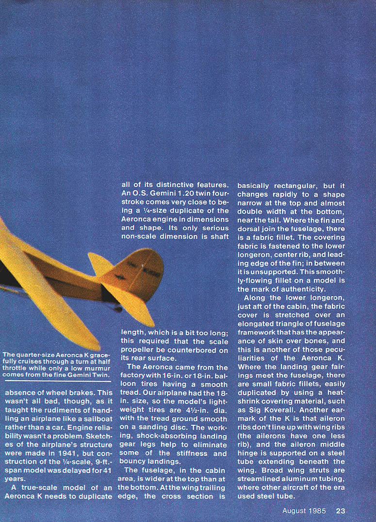
The prototype was one of the more popular flight trainers during the late 1930s and 1940s and an all-time favorite of those who flew just for the love of it. The quarter-scale, 9-ft. version featured here, with its realistic flight and sound when powered by the O.S. Gemini twin, shows why the full-size plane had so much appeal. Detail the model to the limits of your abilities — my model won first in Giant Scale at the 1984 National Contest. — Bob Wischer
Quarter-scale model and powerplant
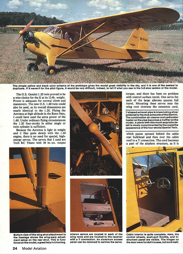
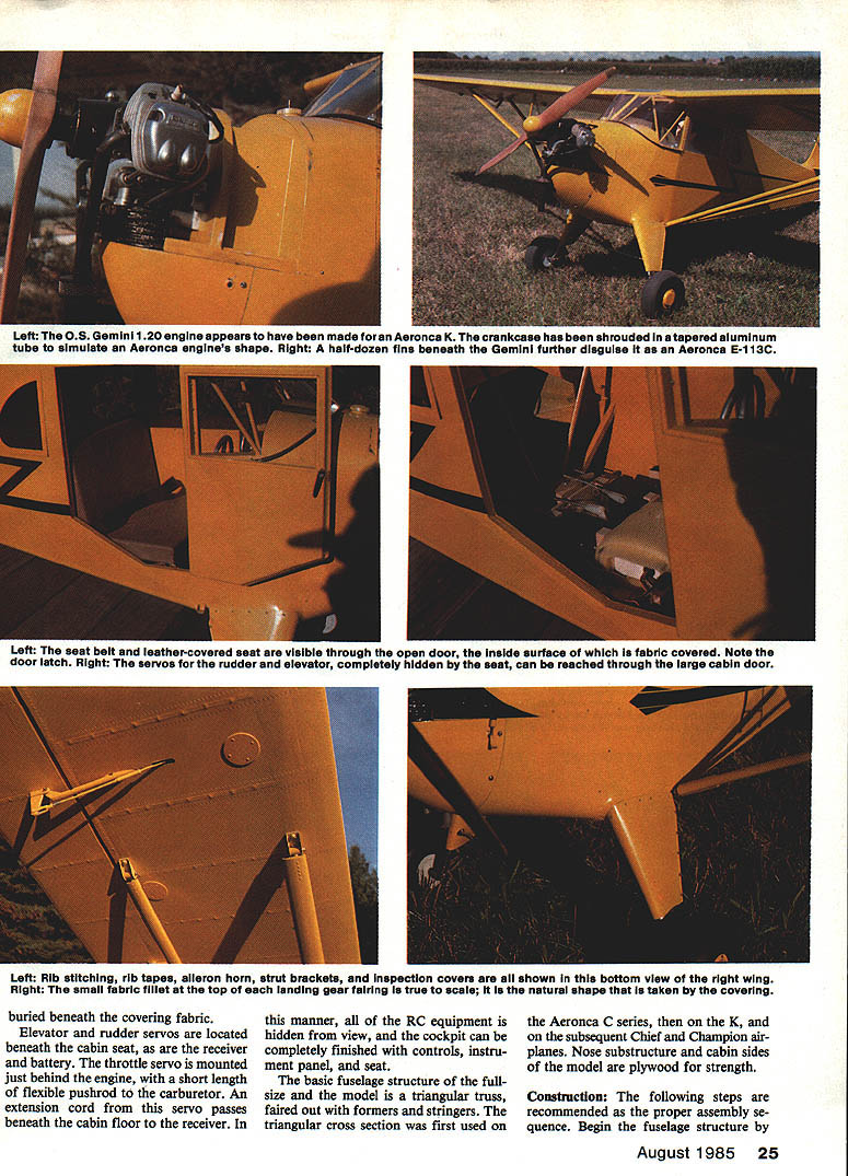
A true-scale model of an Aeronca K needs to duplicate all of its distinctive features. An O.S. Gemini 1.20 twin four-stroke closely matches a 1/4-size duplicate of the Aeronca engine in dimensions and shape; its only significant non-scale dimension is a slightly long shaft, which required that the scale propeller be counterbored on its rear surface. The O.S. Gemini 1.20 proved to be a wise choice at its 12-lb. installation weight — power is adequate for normal climb and maneuvers. The newer O.S. 1.60 twin could also be used; its overall dimensions are nearly identical to the 1.20 and would be useful for high-altitude flying.
A Y-shaped exhaust pipe was made from brass tubing silver-soldered to the Gemini's stub exhausts. The combination air cleaner and carburetor heater on the pipe becomes the model's muffler. An antenna lead (or cord) passes upward behind the cabin rear bulkhead and then over the cabin roof to a Y connection; the cord becomes part of the airplane structure, buried beneath the covering fabric.
Because the Aeronca is light and flies slowly with the 1.20 engine, there is no need for high-energy servos. I used Tech RC Titans with 38 in.-oz. output torque with no problems. One servo per large aileron assures full travel. Mounting these servos near the wing root shortens extension cords. Elevator and rudder servos are located beneath the cabin seat, along with the receiver and battery. The throttle servo is mounted just behind the engine with a short flexible pushrod to the carburetor; an extension cord passes beneath the cabin floor to the receiver. This hides all RC equipment and allows a completely finished cockpit with controls, instrument panel, and seat.
Distinctive full-size features to model
- Landing gear came from the factory with 16-in. or 18-in. balloon tires having a smooth tread; the full-size had 18-in. tires, so the model's lightweight tires are 4 1/2 in. dia., with the tread smoothed on a sanding disc.
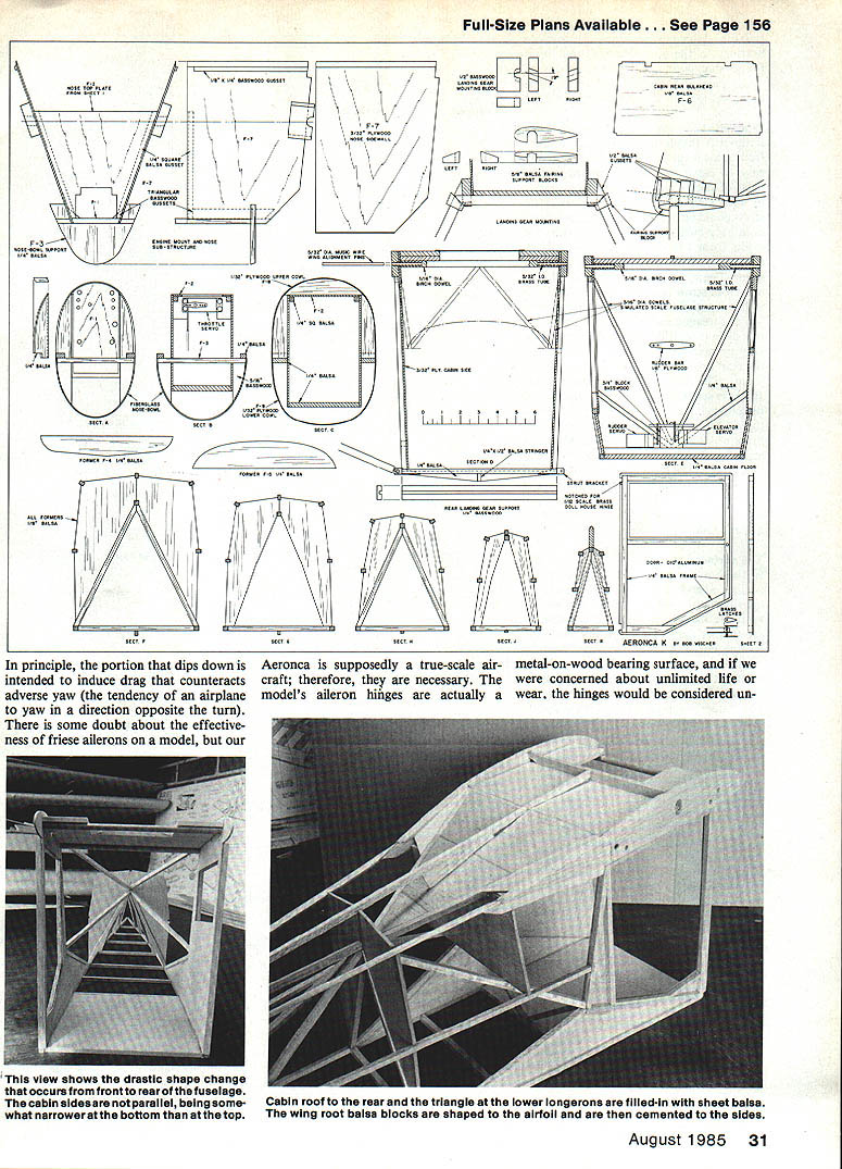
- The fuselage in the cabin area is wider at the top than the bottom. At the wing trailing edge the cross section is basically rectangular but changes rapidly aft to a shape narrow at the top and almost double width at the bottom near the tail.
- Where the fin and dorsal join the fuselage there is a fabric fillet; the covering fabric is fastened to the lower longeron, center rib, and leading edge of the fin, and in between it is unsupported. This smoothly flowing fillet on a model is a mark of authenticity.
- Along the lower longeron, just aft of the cabin, the fabric cover is stretched over an elongated triangle of fuselage framework that has the appearance of skin over bones.
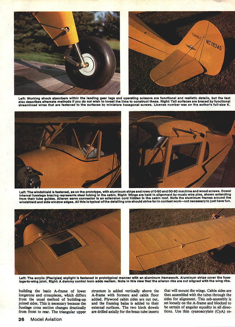
- Where the landing gear fairings meet the fuselage there are small fabric fillets, easily duplicated using a heat-shrink covering such as Sig Koverall.
- Aileron ribs do not line up with wing ribs (the ailerons have one less rib); the aileron middle hinge is supported on a steel tube extending beneath the wing.
- Broad wing struts are streamlined aluminum tubing on the prototype, where other aircraft of the era used steel tube.
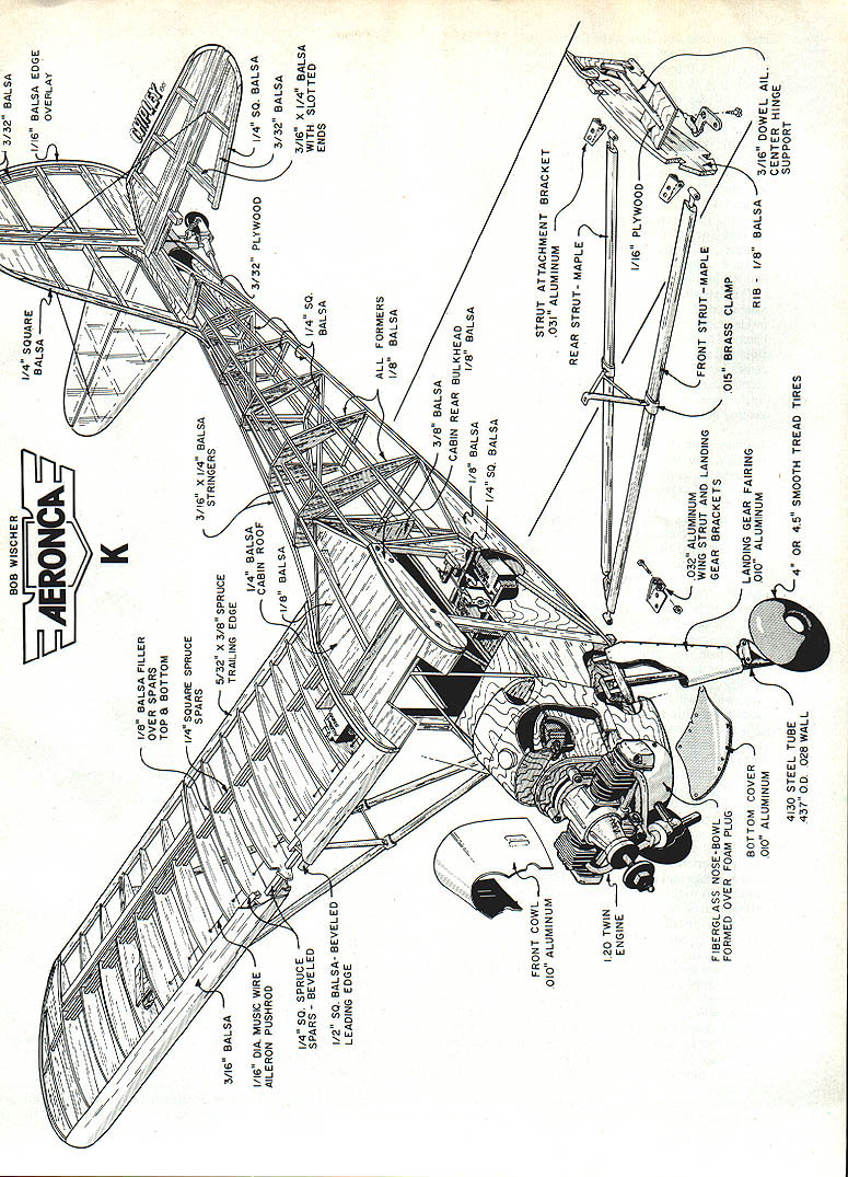
Construction
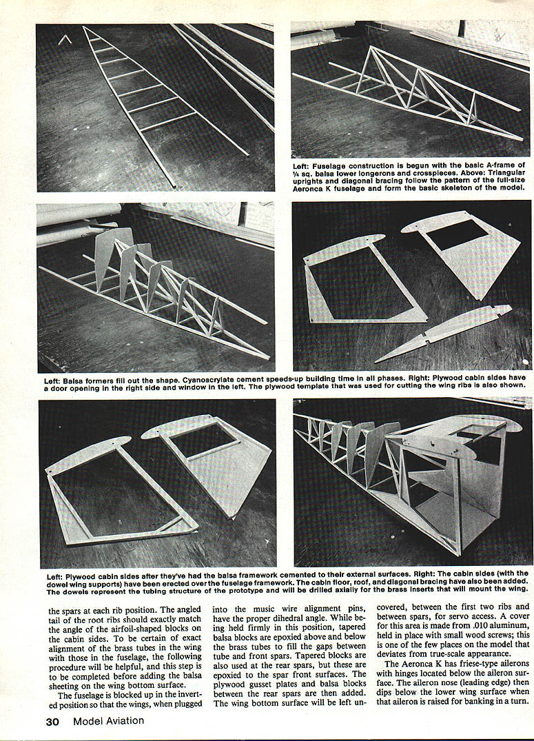
The basic fuselage structure of both the full-size and the model is a triangular truss faired out with formers and stringers. The triangular cross section was first used on the Aeronca C series, then on the K, and later on the Chief and Champion airplanes. Nose substructure and cabin sides of the model are plywood for strength.
Assembly sequence (recommended)
Begin the fuselage by building the basic A-frame of lower longerons and crosspieces. This differs from the usual method of building up joined sides and is necessary because the fuselage cross section changes drastically from front to rear.
- Add the triangular upper structure vertically above the A-frame with formers and the cabin floor.
- Cut out plywood cabin sides and add the framing balsa to their external surfaces.
- Drill the two birch dowels axially for the brass tube inserts that will mount the wings.
- Assemble the cabin sides with the tubes through the sides for alignment and set this sub-assembly loosely on the A-frame. Block it to ensure angular equality in all directions.
- Use thin cyanoacrylate (CyA) cement to freeze the joints at the dowel ends and at the bottom where the cabin sides meet the A-frame.
- Before removing supporting blocks, add the balsa cabin roof and rear triangular bracing to join the sides to the A-frame.
Once this is done the fuselage becomes a rigid assembly. Add 1/4-in. balsa stiffeners in the top area and along the lower longerons. Cement airfoil-shaped blocks of 1/4-in. balsa together to form the angle shown in the fuselage top view and assemble these to the cabin sides. Add stringers, tail post, and plywood stabilizer keel, followed by fin ribs and the leading edge.
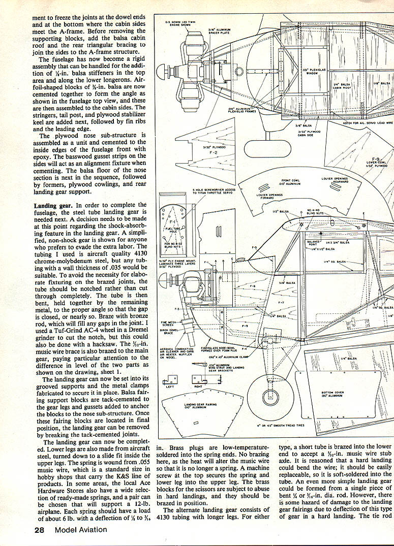
Assemble the plywood nose substructure as a unit and epoxy it to the inside edges of the fuselage front. Basswood gusset strips on the sides act as alignment fixtures when cementing. Next add the balsa floor of the nose section, followed by formers, plywood cowlings, and rear landing gear support.
Landing gear
The steel-tube landing gear is installed next to complete the fuselage. Decide whether to include the shock-absorbing feature; a simplified non-shock gear is shown for those preferring less labor.
- Tubing: I used aircraft-quality 4130 chrome-molybdenum steel, but any tubing with a wall thickness of .035 would be suitable.
- To avoid elaborate fixturing on brazed joints, notch the tube rather than cutting through completely, bend to the proper angle to close the gap, and braze with bronze rod to fill the joint. A Tuf-Grind AC-4 wheel in a Dremel grinder or a hacksaw can be used for notching.
- The 3/32-in. music-wire brace is brazed to the main gear, paying attention to level differences shown on the drawing.
Fit the landing gear into its grooved supports and fabricate metal clamps to secure it. Tack-cement balsa fairing support blocks to the gear legs and add gussets to anchor the blocks to the nose substructure. Once these fairing blocks are located in final position, remove the landing gear by breaking the tack-cemented joints.
Complete the landing gear:
- Lower legs are also aircraft steel, turned down to slide-fit inside the upper legs.
- The spring is wound from .055 music wire (standard K&S size). Each spring should support a 12-lb. airplane, with a load of about 6 lb. and deflection of 1/4 to 1/2 in. Brass plugs are low-temperature-soldered into spring ends (do not braze).
- A machine screw at the top secures the spring and lower leg into the upper leg.
- Brass blocks for the scissors should be brazed in position because they are subject to abuse in hard landings.
Alternate landing gear: 4130 tubing with longer legs, with a short tube brazed into the lower end to accept a 1/2-in. music-wire stub axle. The stub axle should be soft-soldered so it can be easily replaced if bent. A simpler gear could be a single piece of bent 3/32-in. rod, but this can deflect and damage fairings in hard landings. The tube-type gear follows full-scale construction closely.
Engine Mount
The Gemini comes with an aluminum radial mount that is too large for the Aeronca. I mounted the engine on a 1/4-in. aluminum plate to avoid subjecting the mounting lugs to undue loads from uneven bolt tightening on wood. This helps prevent breaking an expensive crankcase rear housing. Handle a Gemini carefully.
Wings and ailerons
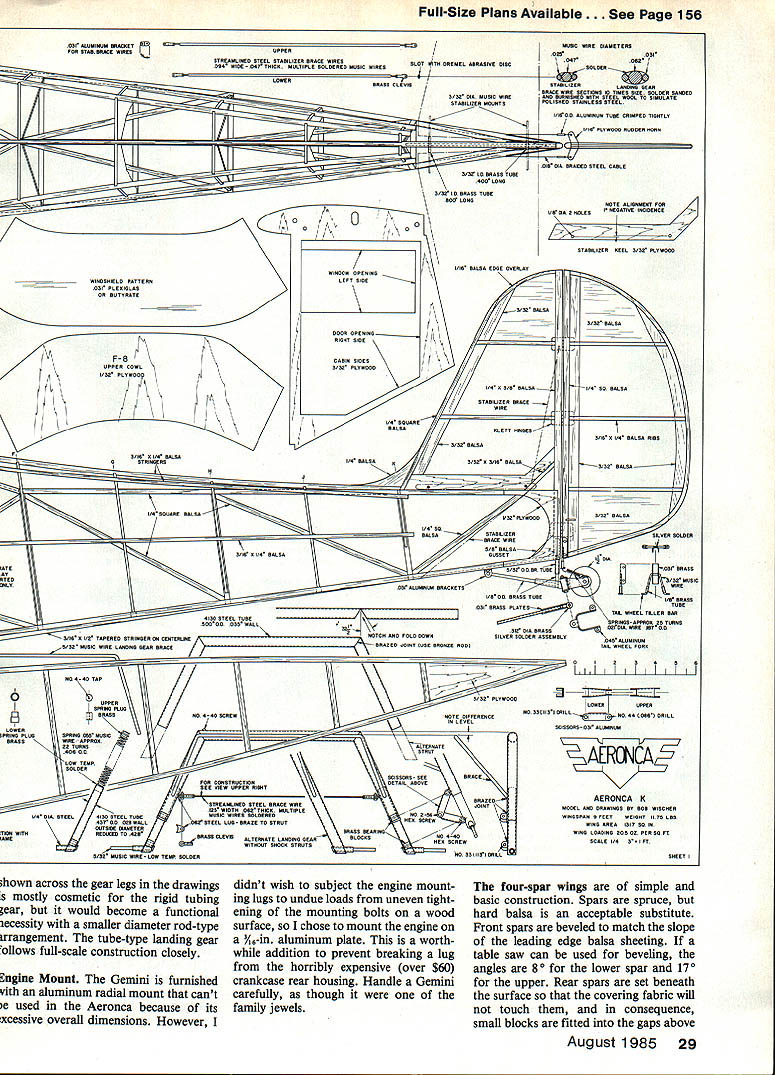
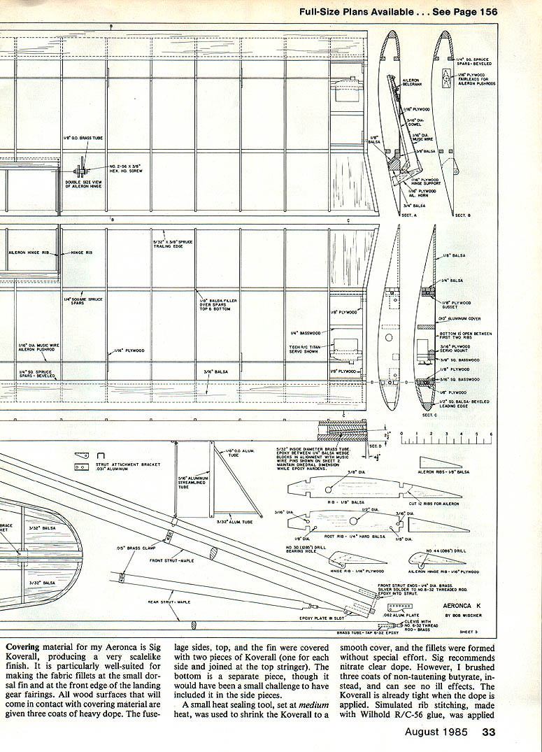
The four-spar wings are simple in construction. Spars are spruce (hard balsa is an acceptable substitute). Front spars are beveled to match the slope of the leading-edge balsa sheeting; if using a table saw, bevel angles are 8° for the lower spar and 17° for the upper. Rear spars are set beneath the surface so that the covering fabric will not touch them; small blocks are fitted into the gaps above the spars at each rib position.
The angled tail of the root ribs should exactly match the angle of the airfoil-shaped blocks on the cabin sides. To ensure alignment of the brass wing-mounting tubes with those in the fuselage, complete the following before adding balsa sheeting to the wing bottom surface:
- Block the fuselage inverted so that the wings, when plugged into the music-wire alignment pins, have the proper dihedral.
- While held in position, epoxy tapered balsa blocks above and below the brass tubes to fill gaps between tube and front spars. Use tapered blocks at the rear spars epoxied to the spar front surfaces.
- Add plywood gusset plates and balsa blocks between the rear spars.
- Leave the wing bottom surface uncovered between the first two ribs and between spars for servo access. Cover this area with .010 aluminum held by small wood screws; this deviates slightly from true scale but provides convenient access.
The Aeronca K has Frise-type ailerons with hinges located below the aileron surface. When the aileron is raised, the aileron nose (leading edge) dips below the lower wing surface to induce drag that counteracts adverse yaw. There is some doubt about effectiveness on a model, but for true scale they are necessary. The model's aileron hinges are a metal-on-wood bearing surface; while not ideal for unlimited life, I have found wear occurs on the metal and not the wood, and the hinge will outlast the model.
Recommended control travels (model):
- Elevator: 1½ in. up, 1½ in. down (extra down motion is due to elevator horn sweep for clearance and is not required).
- Aileron: 1 in. each direction (could be increased to 1½ in.).
- Rudder: 3 in. each direction (maximum allowable).
Wing struts, tail surfaces, and stabilizer
Wing struts on my model are made from scrap soft maple carved to a streamlined shape; they could be made from bass, spruce, or very hard balsa. Strut ends are made from round brass rod with holes drilled and tapped for a brass machine screw; the screw is silver-soldered into the brass rod, the head removed, and the rod drilled axially for the fastening screw. The threaded end is epoxy-cemented into a deep hole in the strut end for a permanent joint.
The inner end of the rear strut is made adjustable with two pieces: remove the head from a No. 10 brass screw, bore a center hole, tap it with a No. 6-32 thread, and epoxy it into the strut end. The brass clevis has a No. 6-32 thread and is locked with a nut; turning the clevis adjusts twist in the wing panel as on the prototype. This adjustment can correct a tendency to turn in flight with neutral rudder and ailerons.
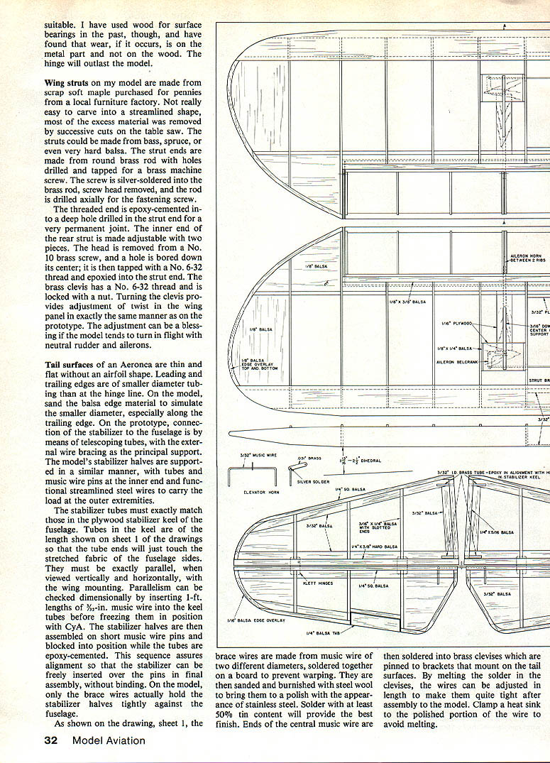
Tail surfaces of an Aeronca are thin and flat without an airfoil shape. Leading and trailing edges are of smaller diameter than at the hinge line; sand the balsa edge material to simulate the smaller diameter, especially along the trailing edge. On the prototype the stabilizer connects to the fuselage via telescoping tubes with external wire bracing as the principal support. The model's stabilizer halves are supported similarly with tubes and music-wire pins at the inner ends and streamlined steel brace wires at the outer extremities.
The stabilizer tubes must exactly match the plywood stabilizer keel in the fuselage. Tubes in the keel are the length shown on the drawing so that tube ends just touch the stretched fabric of the fuselage sides. They must be exactly parallel to the wing mounting both vertically and horizontally. Check parallelism by inserting 1-ft. lengths of 3/32-in. music wire into the keel tubes before fixing them with CyA. Assemble stabilizer halves on short music-wire pins and block them into position while tubes are epoxy-cemented. In final assembly the brace wires hold the stabilizer halves tightly against the fuselage.
Brace wires are made from music wire of two diameters, soldered together on a board to prevent warping, then sanded and burnished with steel wool to a stainless-steel appearance. Use solder with at least 50% tin for the best finish. Ends of the central music wire are soldered into brass clevises pinned to brackets that mount on the tail surfaces. By melting solder in the clevises, length adjustments can be made to make the wires quite tight after assembly. Clamp a heat sink to the polished portion of the wire to avoid melting.
Covering and finishing
Covering material: Sig Koverall produces a very scale-like finish and is particularly well-suited for making fabric fillets at the small dorsal fin and at the front edge of the landing-gear fairings. All wood surfaces that will contact covering material are given three coats of heavy dope. The fuselage sides, top, and fin were covered with two pieces of Koverall joined at the top stringer; the bottom is a separate piece.
A small heat-sealing tool set at medium heat was used to shrink the Koverall to a smooth cover and form fillets without special effort. Sig recommends nitrate clear dope, but I used three coats of non-tautening butyrate and saw no ill effects. Simulated rivet stitching made with Wilhold R/C-56 glue was applied over the wing and tail surface ribs.
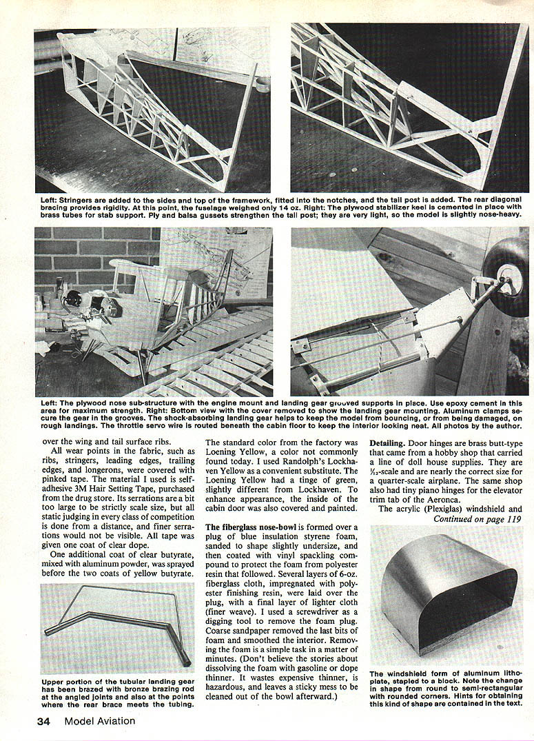
All wear points in the fabric — ribs, stringers, leading edges, trailing edges, and longerons — were covered with pinked tape. I used self-adhesive 3M Hair Setting Tape from a drug store; its serrations are slightly larger than scale but are not visible from judging distances. All tape was given one coat of clear dope. One additional coat of clear butyrate mixed with aluminum powder was sprayed before two coats of yellow butyrate.
Color: The factory color was Lemon Yellow, a shade not common today. I used Randolph's Lockhaven Yellow as a convenient substitute; Lemon Yellow had a tinge of green and was slightly different. To enhance appearance, the inside of the cabin door was also covered and painted.
Fiberglass nose-bowl: Form over a plug of blue insulation styrene foam sanded slightly undersize and coated with vinyl spackling compound to protect the foam from polyester resin. Lay several layers of 6-oz. fiberglass cloth impregnated with polyester finishing resin, finishing with a lighter-weave cloth. Remove foam with a screwdriver and coarse sandpaper; removing the foam is quick and clean. (Do not attempt to dissolve foam with gasoline or thinner — it is hazardous, wastes thinner, and leaves a sticky mess.)
Detailing
- Door hinges: Brass butt-type hinges from dollhouse suppliers are nearly correct for quarter-scale. Tiny piano hinges were used for the elevator trim tab.
- Acrylic (Plexiglas) windshield and skylight: Drape-formed over aluminum sheet forms made from printer's photo plate. Lay the plastic across the form, balance along its centerline, and place in a preheated oven at 250°F for a minute or two. Remove, cool briefly, and the plastic retains the shape. I prefer to cut the plastic to final shape after forming. Use the drawing pattern to confirm fit before cutting. If uncertain, cut a dummy windshield from aluminum sheet, bend it to fit the fuselage, and use it to shape the form.
Flying
The Aeronca model is slightly nose-heavy despite its long tail and short nose moments, but it flies very well in its present balance condition shown on the drawing. It will perform a tail-spin well, so no ballast has been added. The full-size plane was capable of basic aerobatics — a simple loop, split-S, wing-over, and spin — but was not a high-performance acrobat.
Landing characteristics:
- Wheels are quite far forward, producing a tendency to bounce if attempting a three-pointer under anything but ideal conditions. For a bounce-free landing, bring it in a bit fast and feather onto the main wheels.
- Takeoff requires very little rudder. With narrow landing gear, crosswind takeoff or landing can be adventurous; it's best to be lined up directly into the wind.
- No model I have built is easier to fly.
Documentation
A highly detailed three-view drawing of Aeronca K NC 19435 is available in 1/2-scale (1/2 in. = 1 ft.) from Paul Matt's Historical Aviation Album. Price: $5.00 postpaid. Drawing number: 15-103-A. For competition purposes, the drawing should be changed to show one less aileron rib (ailerons are not in line with wing ribs). My 1941 sketches for modeling contain accurate measurements of wing and aileron rib spacing and positions.
Paul Matt's address:
- Historical Aviation Album, P.O. Box 33, Temple City, CA 91780.
Transcribed from original scans by AI. Minor OCR errors may remain.

