
AG-1 Agrivation
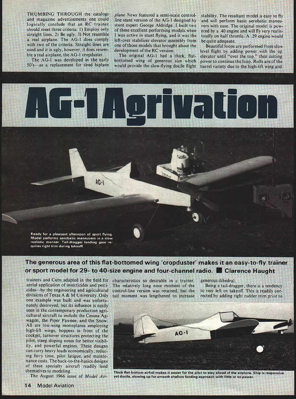
The generous area of this flat-bottomed wing 'cropduster' makes it an easy-to-fly trainer or sport model for 29- to 40-size engine and four-channel radio. ■ Clarence Haught
THUMBING THROUGH the catalogs and magazine advertisements one could logically conclude that an RC trainer should meet three criteria: 1) Employ only straight lines. 2) Be ugly. 3) Not resemble a real airplane. The AG-1 does comply with two of the criteria. Straight lines are used and it is ugly, however, it does resemble a real airplane, the AG-1 cropduster.
The AG-1 was developed in the early 50's as a replacement for tired biplane trainers and Cubs adapted in the field for aerial application of insecticides and pesticides by the engineering and agricultural divisions of Texas A & M University. Only one example was built and was unfortunately destroyed, but its influence is easily seen in the contemporary production agricultural aircraft to include the Cessna Agwagon, the Piper Pawnee, and the Snow. All are low-wing monoplanes employing high-lift wings, hoppers in front of the cockpit, turnover structures protecting the pilot, steep sloping noses for better visibility, and powerful engines. These designs can carry heavy loads economically, reducing ferry time, pilot fatigue, and maintenance costs. The back-to-the-basics designs of these specialty aircraft readily lend themselves to modeling.
The August 1966 issue of Model Airplane News featured a semi-scale control-line stunt version of the AG-1 designed by stunt expert George Aldridge. I built two of these excellent performing models when I was active in stunt flying, and it was the left-over stabilizer elevator assembly from one of those models that brought about the development of the RC version.
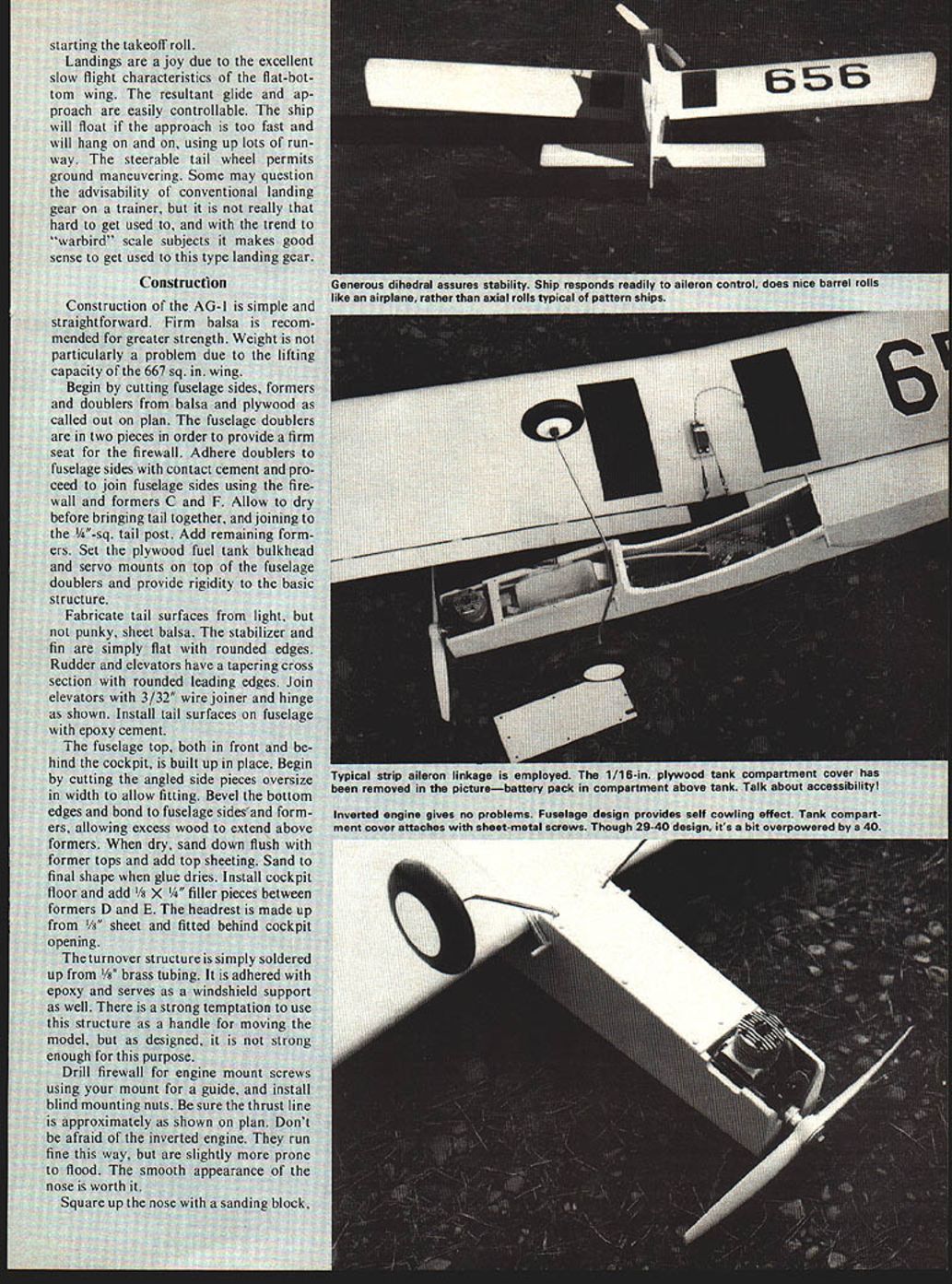
The original AG-1 had a thick, flat-bottomed wing of generous size which would provide the slow-flying docile flight characteristics so desirable in a trainer. The resultant model is easy to fly and will perform basic aerobatic maneuvers with ease. The original model is powered by a .40 engine and will fly very realistically on half throttle. A .29 engine would be quite adequate.
Beautiful loops are performed from slow level flight by adding power with the up elevator until "over the top," then cutting power to continue the loop. Rolls are of the barrel variety due to the high-lift wing and generous dihedral.
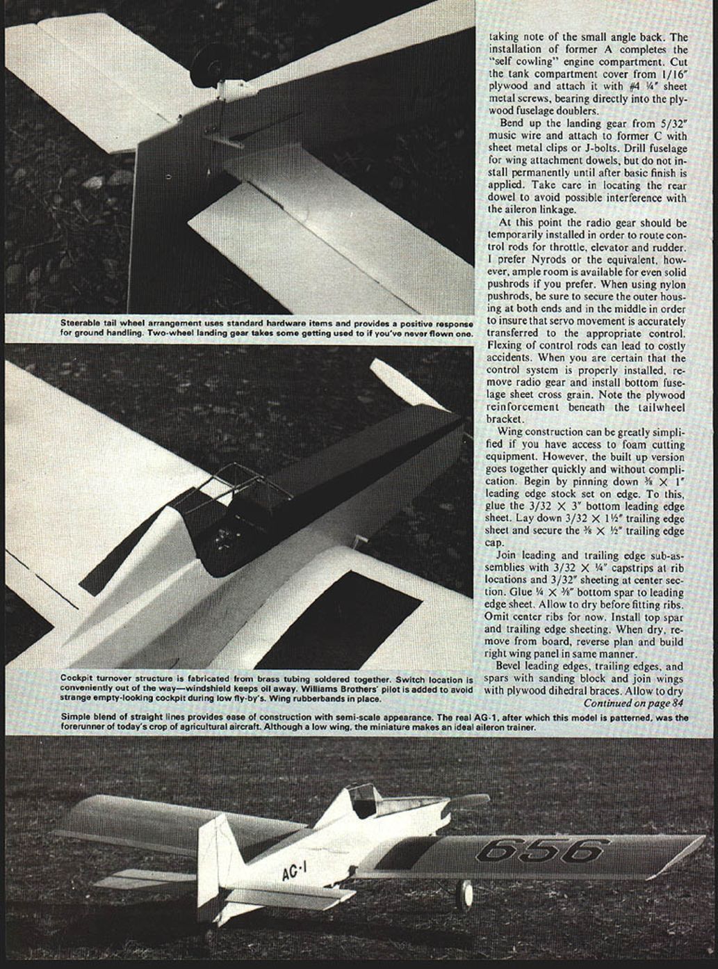
Being a tail-dragger, there is a tendency to veer left on takeoff. This is readily corrected by adding right rudder trim prior to takeoff. Landings are a joy due to the excellent slow flight characteristics of the flat-bottom wing. The resultant glide and approach are easily controllable. The ship will float if the approach is too fast and will hang on and on, using up lots of runway. The steerable tail wheel permits ground maneuvering. Some may question the advisability of conventional landing gear on a trainer, but it is not really that hard to get used to, and with the trend to "warbird" scale subjects it makes good sense to get used to this type landing gear.
Construction
Construction of the AG-1 is simple and straightforward. Firm balsa is recommended for greater strength. Weight is not particularly a problem due to the lifting capacity of the 667 sq. in. wing.
Begin by cutting fuselage sides, formers and doublers from balsa and plywood as called out on plan. The fuselage doublers are in two pieces in order to provide a firm seat for the firewall. Adhere doublers to fuselage sides with contact cement and proceed to join fuselage sides using the firewall and formers C and F. Allow to dry before bringing tail together, and joining to the 1/8"-sq. tail post. Add remaining formers. Set the plywood fuel tank bulkhead and servo mounts on top of the fuselage doublers and provide rigidity to the basic structure.
Fabricate tail surfaces from light, but not punky, sheet balsa. The stabilizer and fin are simply flat with rounded edges. Rudder and elevators have a tapering cross section with rounded leading edges. Join elevators with 3/32" wire joiner and hinge as shown. Install tail surfaces on fuselage with epoxy cement.
The fuselage top, both in front and behind the cockpit, is built up in place. Begin by cutting the angled side pieces oversize in width to allow fitting. Bevel the bottom edges and bond to fuselage sides and formers, allowing excess wood to extend above formers. When dry, sand down flush with former tops and add top sheeting. Sand to final shape when glue dries. Install cockpit floor and add 1/8" x 1/4" filler pieces between formers D and E. The headrest is made up from 1/8" sheet and fitted behind cockpit opening.
The turnover structure is simply soldered up from 1/8" brass tubing. It is adhered with epoxy and serves as a windshield support as well. There is a strong temptation to use this structure as a handle for moving the model, but as designed, it is not strong enough for this purpose.
Drill firewall for engine mount screws using your mount for a guide, and install blind mounting nuts. Be sure the thrust line is approximately as shown on plan. Don't be afraid of the inverted engine. They run fine this way, but are slightly more prone to flood. The smooth appearance of the nose is worth it.
Square up the nose with a sanding block.
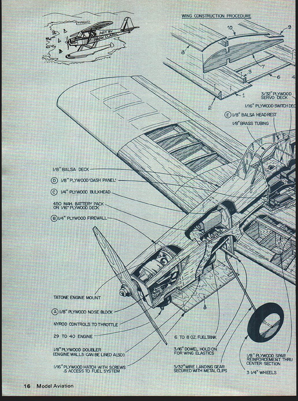
WING CONSTRUCTION PROCEDURE
- 3/32" PLYWOOD SERVO DECK
- 1/16" PLYWOOD SWITCH DECK
- E 1/8" BALSA HEADREST
- 1/8" BRASS TUBING
- 1/8" BALSA DECK
- D 1/8" PLYWOOD 'DASH PANEL'
- C 1/4" PLYWOOD BULKHEAD
- 450 mAh BATTERY PACK ON 1/16" PLYWOOD DECK
- B 1/4" PLYWOOD FIREWALL
- TATONE ENGINE MOUNT
- A 1/8" PLYWOOD NOSE BLOCK
- NYLON ROD CONTROLS TO THROTTLE
- 29 TO 40 ENGINE
- 1/8" PLYWOOD DOUBLER (ENGINE WALLS CAN BE LINED ALSO)
- 1/16" PLYWOOD HATCH WITH SCREWS IS ACCESS TO FUEL SYSTEM
- 6 TO 8 OZ. FUEL TANK
- 3/16" DOWEL HOLD-ON FOR WING ELASTICS
- 5/32" WIRE LANDING GEAR SECURED WITH METAL CLIPS
- 1/8" PLYWOOD SPAR REINFORCEMENT THRU CENTER SECTION
- 3 1/4" WHEELS
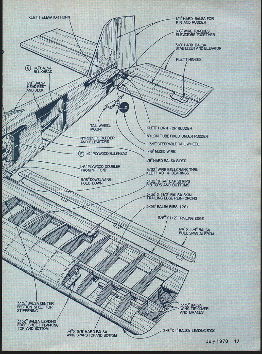
KLETT ELEVATOR HORN
1/4" HARD BALSA FOR FIN & RUDDER
1/16" WIRE TORQUES ELEVATORS TOGETHER
3/8" HARD BALSA STABILIZER AND ELEVATOR
KLETT HINGES
TAIL WHEEL MOUNT
KLETT HORN FOR RUDDER
NYLON TUBE FIXED UNDER RUDDER
NYRODS TO RUDDER AND ELEVATORS
1 3/8" STEERABLE TAIL WHEEL
1/16" MUSIC WIRE
1/8" BALSA BULKHEAD
1/8" BALSA HEAD REST AND DECK
1/4" PLYWOOD BULKHEAD
1/8" PLYWOOD DOUBLER FROM 'F' TO 'B'
3/16" DOWEL WING HOLD DOWN
3/32" WIRE BELLCRANK THRU KLETT AB-4 BEARINGS
1/8" HARD BALSA SIDES
3/32" X 1/4" CAP STRIPS RIB TOPS AND BOTTOMS
3/32" X 1 1/2" BALSA SKIN TRAILING EDGE REINFORCING
3/32" BALSA RIBS (26)
3/8" X 1/2" TRAILING EDGE
1/4" X 1 1/4" BALSA FULL SPAN AILERON
3/32" BALSA WING TIP COVER AND BRACES
3/8" X 1" BALSA LEADING EDGE
1/4" X 3/8" HARD BALSA WING SPARS TOP AND BOTTOM
3/32" BALSA CENTER SECTION SHEET FOR STIFFENING
3/32" BALSA LEADING EDGE SHEET - PLANKING TOP AND BOTTOM taking note of the small angle back. The installation of former A completes the "self cowling" engine compartment. Cut the tank compartment cover from 1/16" plywood and attach it with #4 x 1/4" sheet metal screws, bearing directly into the plywood fuselage doublers.
Bend up the landing gear from 5/32" music wire and attach to former C with sheet metal clips or J-bolts. Drill fuselage for wing attachment dowels, but do not install permanently until after basic finish is applied. Take care in locating the rear dowel to avoid possible interference with the aileron linkage.
At this point the radio gear should be temporarily installed in order to route control rods for throttle, elevator and rudder. I prefer Nyrods or the equivalent, however, ample room is available for even solid pushrods if you prefer. When using nylon pushrods, be sure to secure the outer housing at both ends and in the middle in order to insure that servo movement is accurately transferred to the appropriate control. Flexing of control rods can lead to costly accidents. When you are certain that the control system is properly installed, remove radio gear and install bottom fuselage sheet cross grain. Note the plywood reinforcement beneath the tailwheel bracket.
Wing construction can be greatly simplified if you have access to foam cutting equipment. However, the built up version goes together quickly and without complication. Begin by pinning down 3/8" x 1" leading edge stock set on edge. To this, glue the 3/32" x 3/8" bottom leading edge sheet. Lay down 3/32" x 1 1/2" trailing edge sheet and secure the 3/8" x 1/2" trailing edge cap.
Join leading and trailing edge sub-assemblies with 3/32" x 1/4" capstrips at rib locations and 3/32" sheeting at center section. Glue 1/4" x 3/8" bottom spar to leading edge sheet. Allow to dry before fitting ribs. Omit center ribs for now. Install top spar and trailing edge sheeting. When dry, remove from board, reverse plan and build right wing panel in same manner.
Bevel leading edges, trailing edges, and spars with sanding block and join wings with plywood dihedral braces. Allow to dry.
Agrivation/Haught
continued from page 18
thoroughly. Fit center ribs, cutting out sections as needed. Install leading edge sheeting and center-section planking. Shape sheet wing tips, as shown by typical section. Cap tops of ribs with 1/4" x 3/32" strips. Sand wing structure, rounding leading and trailing edge members to final shape.
Cut ailerons from 1/4" x 1-1/4" trailing edge stock and sand to shape. Install 3/32" wire horns in Klett A-B-4 bearings and hinge to wing. Horns should be bent forward as shown to insure more up aileron travel than down. This is necessary to insure smooth entry into turns with a high lifting airfoil. Fabricate plywood servo doubler to fit the servo to be used and install as shown. Cut out planking to accommodate servo. Standard Du-Bro aileron linkage is recommended.
This completes the basic structure. Give all components a final sanding and proceed with your favorite covering and finishing procedure. The iron-on coverings are satisfactory, but I prefer the more traditional methods. I suggest fabric for the wings either ironed-on Coverite, or dope-on silk or Silron, and dope-on Silkspan over bare wood parts. Silkspan is easily applied with a 75% thinner–25% dope mixture, brushed through the paper after preparing the wood by application of two coats of clear dope, sanding after the first coat only. Approximately five additional coats of dope, thinned only enough for brushing, sanded lightly between coats, will provide an excellent base for color coats. Color may be either dope or epoxy enamel.
Installation of windshield, wheels, tailwheel assembly, engine, tank, and radio, completes the model. Band on the wing and check for alignment. Trim wing saddles, if necessary, to level up wings. Check balance point as shown on plans and add weight, if required, to bring ship into balance. Model can be slightly nose-heavy, but not tail-heavy. Anchor ballast securely. Check control travel and neutral settings with trim set in center. Be sure controls travel in proper direction. Go out and dust a few crops!
hardened epoxy can then be finished by sanding.
Since considerable force is required to drape the heat-softened canopy material over the form, a means is required to anchor it to the work table. Stretching the material is similar to force needed to stretch a sheet of rubber. We usually drill 3/16" diameter holes into the bottom of the form and epoxy 1/2" long dowels into the holes, set flush with the bottom. One end of a 1 x 2 pine board is fastened to the dowels with wood screws. Its other end is clamped to the work table, providing a rigid mount for the form so that it is suspended in air away from the table. Forms with deep compound curves demand the most rigid mountings, because the canopy material must be stretched in two directions. The work table should be moved close to the oven that will be used for heat softening the plastic, to shorten the time from oven to form.
The sheet of transparent plastic is prepared by cutting to size with a saw. Plexiglass cannot be cut successfully with a tin shear because it will crack in unwanted directions and any edge notches will be a starting point for a tear when being stretched. Its dimensions should be 3 or 4" greater than the mold size because we need to drill holes along two edges. Wood grip strips are bolted to opposite sides of two edges of the plastic to provide a means of applying a uniform force during forming.
The wood strip should be held firmly to the plastic with C-clamps while slowly drilling through to prevent cracking as the drill penetrates. Bolts and nuts are then assembled and tightened securely. Using 1/4" softwood strips, the #10 bolts should be on 3" centers for maximum security. For thinner wood, use more bolts. The assembly is then suspended in the oven by means of screw hooks threaded into the wood.
Plexiglas should be heated at an oven temperature of 250°F. It is not ready to stretch until it sags considerably in the oven. While waiting for the material to soften, the form needs to be heated with a hair dryer or heat lamp. Without this preheating of the form, we have found that plastic hardens too rapidly when it comes in contact with a cold form and a complete canopy cannot be formed. If this should happen, the plastic can be returned to the oven for a second attempt. It will return to its original shape unless torn or mutilated severely. Gloves or mittens should be worn as the bolts become very hot. The stretching should be done in one swift motion downward, wrapping the plastic completely around the mold so that the hands meet beneath the mold. The hardening takes place in a few seconds, so lose no time in transferring the plastic from oven to form.
If the canopy has no compound curves, as in a simple curved windshield, the process is much simplified. The form can be a sheet of aluminum, bent to shape around a large wood dowel or rolling pin. The form is placed in the oven with the plastic balanced at its crest, and that will cause the plastic to neatly wrap itself around the form. Removed from the oven and cooled, it is ready for trimming.
After forming, the excess material is best removed with an abrasive cut-off wheel in a Dremel tool. We have found this to be the safe way of cutting without damage. Small changes can be made by sanding. We have had no success with scissors which
Transcribed from original scans by AI. Minor OCR errors may remain.

