
Air Cadet
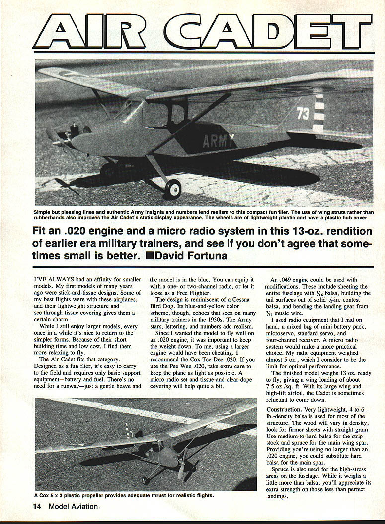
Fit an .020 engine and a micro radio system in this 13-oz. rendition of earlier-era military trainers, and you'll see that sometimes small is better.
I've always had an affinity for smaller models. My first models were stick-and-tissue designs, and some of my best flights came from airplanes with lightweight structure and see-through tissue covering — they have a certain charm. I still enjoy larger models, but it's nice to return occasionally to simpler forms. Short building time and low cost make them relaxing to build and fly.
The Air Cadet is a compact fun flier that is easy to carry to the field and requires only basic support equipment — battery or fuel. There's no need for a runway; a gentle heave gets it airborne. It can be equipped with a one- or two-channel radio, or flown as a free flighter. The design is reminiscent of a Cessna Bird Dog; the blue-and-yellow color scheme and 1930s-style Army stars and markings add realism.
To make the model fly well on an .020 engine it was important to keep weight down. I recommend the Cox Tee Dee .020. A Pee Wee .020 will work, but take extra care to minimize weight (micro radio and tissue-and-clear-dope covering help). An .049 could be used only with modifications: sheet the entire fuselage with 1/8-in. balsa, build tail surfaces from solid 1/8-in. contest balsa, and bend the landing gear from 3/32-in. music wire.
I used assorted radio gear on the prototype — mini battery pack, microservo, standard servo, and four-channel receiver — but a micro radio set is a more practical choice. My gear weighed almost 5 oz., which I consider the performance limit. The finished model weighs about 13 oz. ready to fly, giving a wing loading of roughly 7.5 oz./sq. ft. With its large wing and high-lift airfoil, the Cadet can be reluctant to come down.
Construction
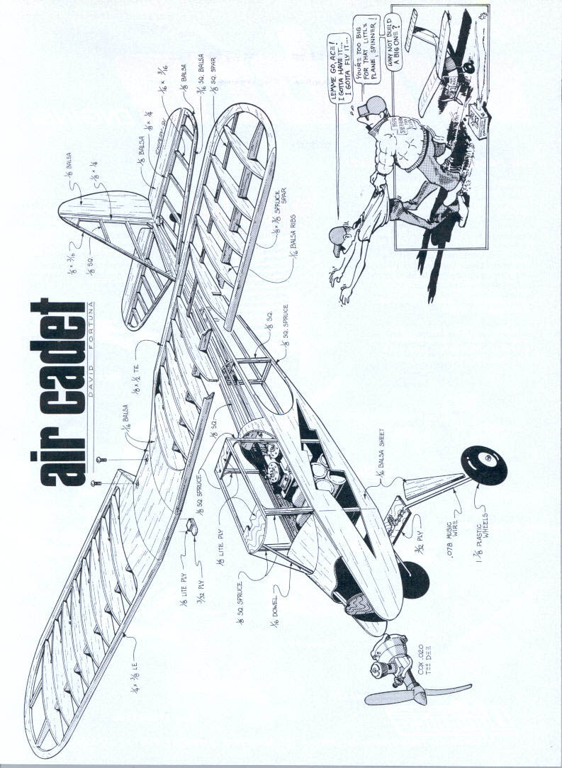
Very lightweight 4- to 6-lb.-density balsa is used for most of the structure. Wood density varies; look for firmer sheets with straight grain. Use medium-to-hard balsa for strip stock and spruce for the main wing spar and other high-stress areas. If you truly limit yourself to an .020 engine, a hard balsa main spar may be substituted for spruce. Spruce adds strength that pays off on less-than-perfect landings.
Wing Build
- Build the wing in three sections. Make the center section first to aid alignment of the outer panels.
- Glue dihedral braces to the center-section leading-edge (LE) spar. When dry, pin the LE spar and the trailing edge (TE) in place.
- Add bottom sheeting between the LE spars and TE on the center and outer sections (sheet 1/16-in. balsa between ribs). Glue the C1 ribs in place and glue rear filler blocks between the ribs, flush with the top surface.
- Drill holes for the 4-40 nylon hold-down bolts. Sheet the top of the wing, leaving cutouts for 1/16-in. plywood inserts to support the bolts. To prevent plywood splitting, drill the holes before cutting the inserts. Make sure cutouts align with the previously drilled holes, then glue the balsa sheet and inserts in place.
- Build the outer panels in the same manner. Check that leading edges and spars align with the center section. Pin the center section flat, block up the wing tip about 2 in., then join and glue the panels. After drying, add the C1 rib and sheet the remaining top sections.
- Sand the wing tips to contour. Very lightweight balsa sands easily — take care not to overdo it.
Wing struts are optional and mainly add static-display realism. Strut attachment options:
- Aluminum tab secured with two 3/8-in. wood screws at one end and 3/32-in. music-wire pin plugs at the other.
- 1/16-in.-OD aluminum tube epoxied into the fuselage for the strut attach point.
Tail surfaces
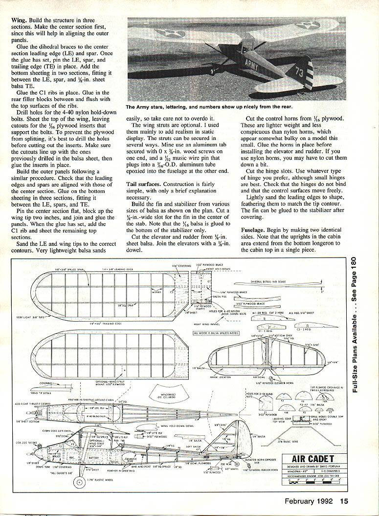
Build the fin and stabilizer from the balsa sizes shown on the plan. Cut a 1/16-in.-wide slot in the center of the stabilizer to accept the fin. Note that 1/8-in. balsa is glued to the bottom of the stabilizer only.
- Cut elevator and rudder from 1/8-in. sheet balsa. Join the elevator halves with a 1/8-in. dowel.
- Cut control horns from 1/16-in. plywood; these are lighter and less conspicuous than nylon horns on a model this small. Glue the plywood horns in place before installing the elevator and rudder. If you use nylon horns, you may need to trim them down.
- Cut hinge slots and install your preferred small hinges. Check that hinges don't bind and that controls move freely.
- Lightly sand and feather the leading edges to match tip contours. Glue the fin to the stabilizer after covering.
Fuselage
- Make two identical sides. Note that the cabin-area uprights extend from the bottom longeron to the cabin top in a single piece.
- Glue the sides together over the plan, add formers and stringers, and sheet the top and bottom between formers. Fit the wing saddle and firewall, and glue any plywood doublers at high-stress areas.
- Shape the nose block around the engine mount. Bend the landing gear from 3/32-in. music wire and secure it with plywood plates and blind nuts or epoxy as shown on the plan. Fit lightweight wheels and plastic hub covers.
- Cut cabin windows and cockpit openings after covering. Install radio gear, servos, and battery; check center of gravity and make final control-throw adjustments and linkage rigging.
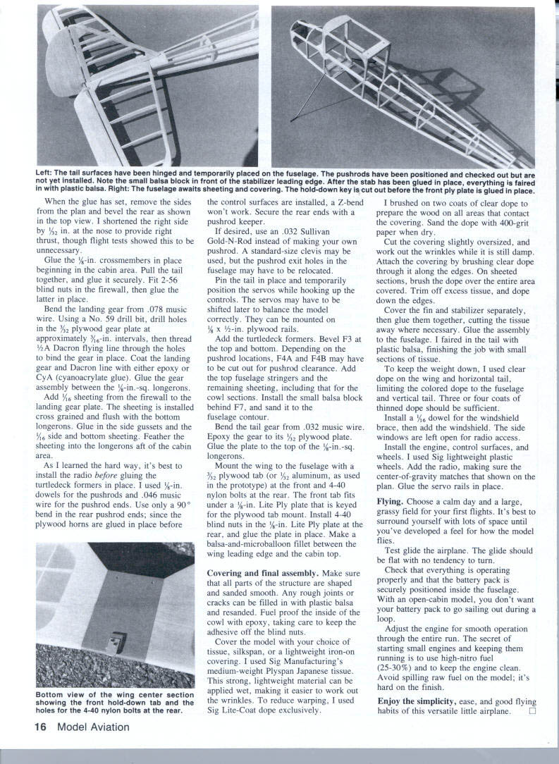
- When glue has set, remove the sides from the plan and bevel the rear as shown on the top view. (A small right-side nose shortening of 1/32 in. was used on the prototype to add right thrust; flight tests showed it was unnecessary.)
- Glue 1/8-in. crossmembers in place beginning at the cabin area. Pull the tail together and glue securely. Fit 2-56 blind nuts in the firewall, then glue the firewall in place.
- Using a No. 59 drill bit, drill holes in the 3/32-in. plywood gear plate at approximately 7/16-in. intervals and thread 2-56 blind nuts into the plate. Coat the landing gear and Dacron line with epoxy or CA, then glue the gear assembly between the 1/8-in.-sq. longerons.
- Add 1/16-in. sheeting from the firewall to the landing gear plate. Install the sheeting cross-grained and flush with the bottom longerons. Glue side gussets and 1/16-in. side and bottom sheeting, feathering sheeting into the longerons aft of the cabin.
- Install radio before gluing turtledeck formers. I used 1/8-in. dowels for pushrods and .046-in. music wire for pushrod ends. Use only a 90° bend in the rear pushrod ends — a Z-bend won't work because plywood horns are glued in place before the control surfaces are installed. Secure rear ends with a pushrod keeper.
- Option: use an .032-in. Sullivan Gold-N-Rod instead of homemade pushrods. Standard-size clevises may be used; pushrod exit holes may need relocation.
- Temporarily position servos while hooking up controls; they may need to shift later to balance the model. Mount servos on 1/8 x 1/2-in. plywood rails if desired.
- Add turtledeck formers (bevel F3 top and bottom). Depending on pushrod routing, cut F4A and F4B for clearance as needed. Add top fuselage stringers and remaining sheeting, including cowl sections. Install the small balsa block behind F7 and sand to contour.
- Bend tail gear from .032-in. music wire, epoxy to its 1/8-in. plywood plate, and glue the plate to the top of the 1/8-in.-sq. longerons.
- Mount the wing with a 3/32-in. plywood tab (or 3/32-in. aluminum tab) at the front and 4-40 nylon bolts at the rear. The front tab fits under a 1/8-in. Lite Ply plate keyed for the tab. Install 4-40 blind nuts in the 1/8-in. Lite Ply rear plate and glue the plate in place. Make a balsa-and-microballoon fillet between the wing leading edge and cabin top.
Covering and final assembly
- Shape and sand all parts smooth. Fill any rough joints or cracks with plastic balsa and resand.
- Fuel-proof the inside of the cowl with epoxy; avoid getting adhesive on blind nuts.
- Cover with tissue, silkspan, or a lightweight iron-on covering. I used Sig’s medium-weight Plyspan Japanese tissue; it is strong, lightweight, and can be applied wet to ease wrinkle removal. To reduce warping, I used Sig Lite-Coat dope exclusively.
- Brush two coats of clear dope on wood areas that contact the covering. Sand the dope with 400-grit paper when dry.
- Cut covering slightly oversized and work out wrinkles while damp. Attach covering by brushing clear dope through it along edges. On sheeted sections, brush dope over the entire covered area. Trim excess tissue and dope down the edges.
- Cover fin and stabilizer separately, glue them together, cut away tissue where necessary, and secure the assembly to the fuselage. Fair the tail with plastic balsa and finish with small tissue patches.
- To save weight, use clear dope on the wing and horizontal tail and colored dope only on the fuselage and vertical tail. Three to four coats of thin nitrocellulose dope should be sufficient.
- Install a 1/8-in.-thick dowel for the windshield brace and add the windshield. Leave side windows open for radio access.
- Install engine, control surfaces, wheels (lightweight plastic), radio, and servos. Verify the center-of-gravity matches the plan and glue servo rails in place.
Flying
- Choose a calm day and a large grassy field for initial flights. Allow plenty of space until you develop a feel for the model.
- Test-glide the airplane. The glide should be flat with no tendency to turn.
- Check all systems and ensure the battery pack is securely positioned inside the fuselage; with an open cabin you don't want the battery to fly out during aerobatics.
- Adjust the engine for smooth operation through the entire run. Small-engine starting and running tips: use high-nitro fuel (25–30%) and keep the propeller clean. Avoid spilling raw fuel on the finish.
- Enjoy the simplicity, ease, and good flying habits of this versatile little airplane.
Transcribed from original scans by AI. Minor OCR errors may remain.

