
AIRCHILD
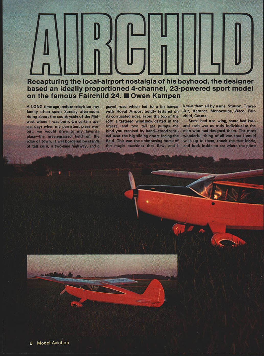
Recapturing the local-airport nostalgia of his boyhood, the designer based an ideally proportioned 4-channel, .23-powered sport model on the famous Fairchild 24. Owen Kampen
A long time ago, before television, my family often spent Sunday afternoons riding about the countryside of the Midwest where I was born. On certain special days when my persistent pleas won out, we would drive to my favorite place—the green-grassed field on the edge of town. It was bordered by stands of tall corn, a two-lane highway, and a gravel road which led to a tin hangar with Royal Airport boldly lettered on its corrugated sides. From the top of the roof a tattered windsock darted in the breeze, and two tall gas pumps—the kind you cranked by hand—stood sentinel near the big sliding doors facing the field. This was the unimposing home of the magic machines that flew, and I knew them all by name: Stinson, Travel-Air, Aeronca, Monocoupe, Waco, Fairchild, Cessna.
Some had one wing, some had two, and each was as truly individual as the man who had designed them. The most wonderful thing of all was that I could walk up to them, touch the taut fabric, and look inside to see where the pilots sat and the controls and instruments they used.
These were the years aviation history was being made and the little airport and I shared them. In August of 1927, Charles Lindbergh came in the Spirit of St. Louis, and again in June of the following year in his Ryan Brougham to receive an honorary degree from the University where he had failed as a student. Three years later, it was Wiley Post, Harold Gatty, and the fabulous Lockheed Winnie Mae roaring overhead to salute the cheering crowd.
From this same field I had my first airplane ride, flew my first gas model, and participated in my first contest—where I watched Carl Goldberg's revolutionary Zipper climb almost out of sight.
The airport is gone now, a victim of progress, and new office buildings stand where the beautiful planes once flew. Sometimes when the rush-hour traffic slows down enough, I look over at the magic place of my youth and when the late afternoon sun is just right, I can see them still—Stinson, Waco, Monocoupe, Fairchild...
Today, some 40 years later, these have all become collector's items and can be admired at EAA fly-ins around the country. Lovingly restored and cared for, they have earned the label "classic" for reasons other than age, for they fly as nobly as they look, with several of them performing more efficiently than their mass-produced look-alike modern descendants. Their uniqueness is due largely to the fact that they were the product of innovative designers who created airframes capable of outstanding feats in spite of the limited power available at that time (there were a few capable of speeds of well over 150 mph on 140-hp engines). Their distinctive appearance was the result of strong individual concepts and personal aesthetics, for "design by committee" still lay in the future, and sales managers had not yet discovered their power to dictate what the market preferred. So the old planes live on, as a tribute to another time, and another state of mind.
The Airchild is none of these, yet owes its parentage to several of them, with the Fairchild 24 supplying the dominant genes. The goal was to create the classic look of that early era without the accompanying endless hours of construction associated with a true scale model. Then too, previous scale efforts had resulted in models which retained too many of the tricky traits of their full-size counterparts.
To resolve these problems, I decided to begin with the general areas, components, and construction methods of an easy-to-build outstanding flying model. My Air Scout design met these requirements handsomely and so the new lines were laid down over the known quantity of the old.
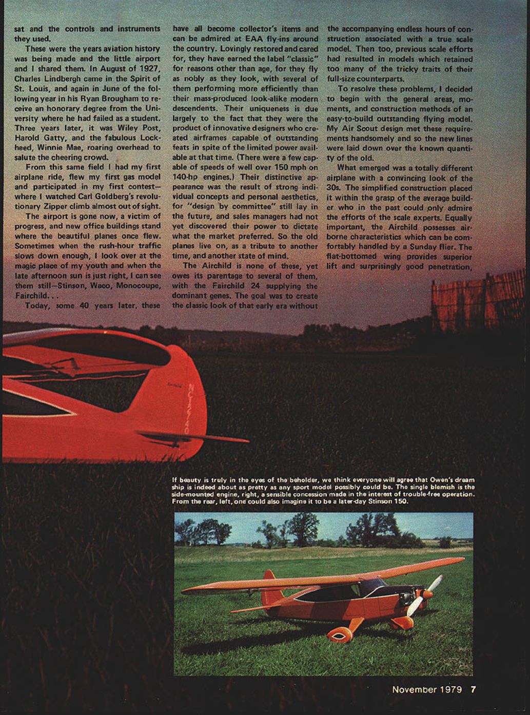
What emerged was a totally different airplane with a convincing look of the '30s. The simplified construction placed it within the grasp of the average builder who in the past could only admire the efforts of the scale experts. Equally important, the Airchild possesses airborne characteristics which can be comfortably handled by a Sunday flier. The flat-bottomed wing provides superior lift and surprisingly good penetration.
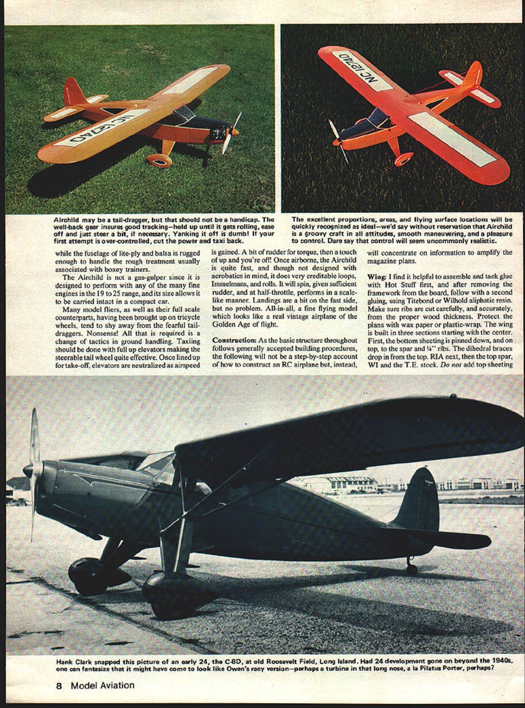
The Airchild may be a tail-dragger, but that should not be a handicap. The well-back gear ensures good tracking—hold up until it gets rolling, ease off and just steer, if necessary. Yanking it off is dumb! If your first attempt is over-controlled, cut the power and taxi back.
While the fuselage of lite-ply and balsa is rugged enough to handle the rough treatment usually associated with boxy trainers, the Airchild is not a gas-gulper since it is designed to perform with any of the many fine engines in the .19 to .25 cu in range, and its size allows it to be carried intact in a compact car.
Many model fliers, as well as their full-scale counterparts, having been brought up on tricycle wheels, tend to shy away from the fearful taildraggers. Nonsense! All that is required is a change of tactics in ground handling. Taxiing should be done with full up elevators making the steerable tail wheel quite effective. Once lined up for take-off, elevators are neutralized as airspeed is gained. A bit of rudder for torque, then a touch of up and you're off. Once airborne, the Airchild is quite fast, and though not designed with acrobatics in mind, it does very creditable loops, Immelmans, and rolls. It will spin, given sufficient rudder, and, at half-throttle, performs in a scale-like manner. Landings are a bit on the fast side, but no problem. All in all, a fine flying model which looks like a real vintage airplane of the Golden Age of flight.
Construction
As the basic structure throughout follows generally accepted building procedures, the following will not be a step-by-step account of how to construct an RC airplane but, instead, will concentrate on information to amplify the magazine plans.
Wing
I find it helpful to assemble and tack-glue with Hot Stuff first, and after removing the framework from the board, follow with a second gluing using Titebond or Willhold aliphatic resin. Make sure ribs are cut carefully and accurately from the proper wood thickness. Protect the plans with wax paper or plastic wrap.
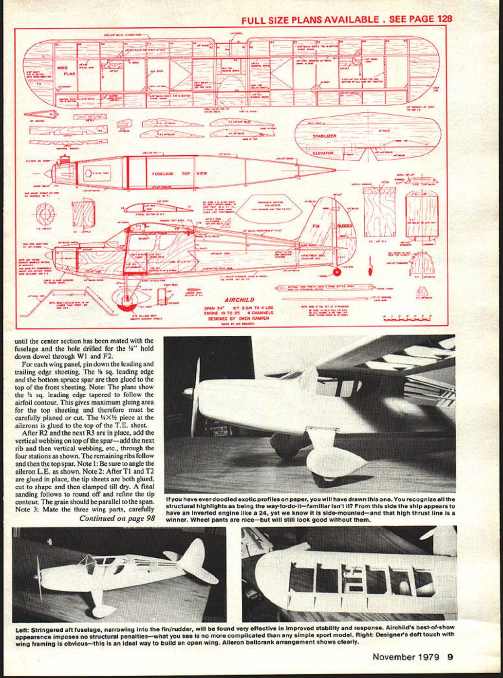
The wing is built in three sections starting with the center. First, the bottom sheeting is pinned down, and on top the spar and 1/4" ribs. The dihedral braces drop in from the top. R1A next, then the top spar, W1, and the trailing-edge stock. Do not add top sheeting until the center section has mated. When the center section has mated, the fuselage hole is drilled and a 1/4" hold-down dowel is installed through W1 to F2.
Wing panel: pin down leading and trailing edge sheeting; the leading edge is tapered to follow the airfoil contour which gives maximum gluing area for the top sheeting and therefore must be carefully planed and cut. A 1/8" aileron is glued to the top trailing-edge sheet. After R2 then R3 are in place, add vertical webbing to the top spar; add the next rib, vertical webbing, etc., through the four stations shown. Remaining ribs follow the top spar. Note the angle of the aileron leading edge as shown. After T1 and T2 are glued in place, tip sheets are glued on both tips, cut to shape and clamped till dry; final sanding follows to round off and refine tip contour. Grain should be parallel to the span. Mate the three wing parts carefully and check the dihedral shown, measured at the trailing edge of the tip ribs. Then top sheeting and cap strips can be added.
If you have ever doodled exotic profiles on paper, you will have drawn this one. You recognize all the structural highlights as being the way-to-do-it—familiar, isn't it? From the side the ship appears to have an inverted engine like a 24, yet we know it is side-mounted—and that high thrust line is a winner. Wheel pants are nice—but it will still look good without them.
Note: The inwash at each wing tip is important and can be warped in after covering. The original was covered in Super MonoKote.
Tail Surfaces
The plans are self-explanatory. All butt joints are made with Hot Stuff or equivalent. The rudder is glued square to the stab before mounting on the fuselage.
Fuselage
The sides are built directly over the plans. As popular lite-ply usually has one smooth and one rough side, make sure to cut a left and a right cabin section. Carefully cut the angles at the cabin openings and dry-fit the pieces before gluing. The cabin top is sheeted with 1/16" balsa and 1/32" strips around the openings. Build up the nose area with scrap 1/16" and 1/8" balsa to take the engine mount. The cowl is cut from 1/8" balsa sheet and shaped to fit around the engine; allow for cowl flanges and muffler if using a glow engine.
Install the radio gear, then check the C.G. at the point shown on the plans. Move the battery and receiver as required to obtain the proper C.G. Balance laterally by adding weight in the wing roots if necessary.
Carefully fit the cabin doors and windscreen. Sand and finish all joints fair and true before covering. Final trim and flying adjustments are straightforward: check control throws, set any necessary throttle/rudder mixes and test in gentle flight before attempting aerobatics.
Contact cement all braces and doublers in place. Formers F2 and F3 go next, using aliphatic resin or epoxy. Keep it all square! Check alignment before gluing and clamping the sides together at the tail, then install F3 and F4. Locate the engine mount flush with the top of F1. Glue and bolt in place before epoxying F1 between the fuse sides. Mount the engine temporarily and tack-glue the hatch, nose, and bottom nose blocks in position, where they can be rough-carved and sanded to shape and positioned to fit the engine. Scrap 1/4" balsa is used in front of FN to complete the cowling. Fit the spinner at this time. Take your time and round all corners for a sleek, smooth front end. The hatch is cut before being removed.
Now the bottom sheeting is added cross-grain for strength. Install rudder and elevator Nyrod tubes. I prefer braided cable for all controls because it is not temperature sensitive. The 1/4" fuse top goes next, then the 1/4" x 1/4" spruce stringers. Fair in the stringers at F4 as shown.
Bend the landing gear wire as indicated. Cut the ply parts of the landing gear mount and epoxy the first to the fuse bottom. Tack-glue the gear wires in place with Hot Stuff, and add the ply spacers between them. They can be wrapped with soft copper wire and soldered. The metal strut attachment strap goes next. Last, the third ply piece is glued and screwed in place to lock it all solidly together. Check the alignment of the gear for evenness and true tacking, then build up the balsa sandwich fairings. Sand smoothly to a streamlined section.
The wheel pants are optional but greatly improve the scale-like look. I made mine removable for grass field operation by attaching the square ply insert to the landing gear. Then the inside of the pants are cut out to make a tight slip-over fit.
The 1/8" x 1/8" bottom stringers are added and sanded to the shape shown on the plans. Fit the 1/8" x 3/8" braces between the sides. Next, carefully align and glue the tail section to the fuse. Everything must be square and true—no tilts or turns. Carve and install fillets on each side of the rudder.
Now the wing can be mated to the fuselage and the 1/4" hold-down dowel installed. The 1/4" ply pieces at the rear of the cabin opening are drilled and tapped to take 1/4" nylon bolts. With the wing attached, carve and fit the fairing on top of the wing to flow smoothly into the fuselage top.
The tail wheel uses a standard Goldberg accessory epoxied and screwed to the fuse.
Engine Notes
After fuel-proofing the tank and engine sections with epoxy, mount the engine with a 0°-0° thrustline.
For an uncluttered front end, I found the Tatone Exhaust Manifold (ACE R/C Catalog 16L269) worked just fine and would recommend it for maximum scale effect. A local modeler chose to mount his engine at a 45° angle in order to accommodate a standard muffler. I found the tank installation easier with the tank positioned on its side rather than upright.
The fuselage was covered with Orange Super MonoKote and the black trim cut from MonoKote trim sheets. The windows and windshield were attached using Hot Stuff sparingly. The wing struts are functional and can be eliminated if desired. Small screws through the metal straps in each end hold them in place. A clevis can be used to connect struts to the fuse if you wish.
Flying
As the plane flies fairly fast, excessive control movements are not necessary. Start with about 1/4 in. deflection on the ailerons and 1/2 in. each way with the tail surfaces. Take-offs with the .23 were quick with a rather short ground run.
While the Clark Y-type airfoil usually causes some ballooning in turns, when mounted at 0° incidence this is minimized and wind penetration surprisingly good. (Incidentally—the Clark Y will still lift until the incidence reaches −2°.) Once airborne, the plane is fast, with good scale speeds reached at half-throttle. Keep the approach speed a bit on the high side until familiar with the plane. Either three-point or wheel landings work well.
That's about it. Enjoy! Enjoy!
Transcribed from original scans by AI. Minor OCR errors may remain.

