

Aircraft Lighting
by CHRIS BATCHELLER
Introduction
Now that I am no longer a beginner, I don't have to worry about my airplane crashing while experimenting with mild aerobatics. What I wanted was something different without the expense of a new airframe or time to build one—bright lights. Literally: add lights to the model.
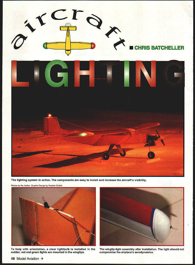
Adding lights will make the aircraft more noticeable at the field, help you find it after a crash in woods or other hard-to-see places, and (with caution and spotters) allow you to fly in times of reduced visibility (not at night). And yes, you'll probably envy the modeler at the club who doesn't have lights.
For this project I used a wing salvaged from a Hobbico Avistar 40. The wing had been built on a jig and therefore had 1/2-inch holes in the ribs from tip to root, which made routing wiring easier. If you build a wing, stack the ribs with the top ribs toward you and drill holes through the stack where you want the wiring to run. If the wing is already constructed, you can cut V-shaped grooves in the bottom of the wing panels to install the wires before recovering. Make sure any wire or wooden structure does not touch the covering. You can also install lights in foam wings.
Materials and tools (high level)
- Lights and bases (red, green, and clear/white)
- Copper wire with double insulation (stiff conductors)
- Soldering iron, flux (soldering paste), and solder
- Heat-shrink tubing
- Epoxy
- Small balsa blocks for light supports
- Drill bits (including an extended-shaft drill bit)
- Brass wire and small brass weight for tunneling holes
- PC board and small toggle switch
- Battery holder and batteries
- Miscellaneous: tape, foam for mounting battery pack, pliers, cutters, sandpaper
Soldering basics
Soldering skill is used throughout this project. If you don't know how to solder, follow these basic steps:
- Use as little solder as possible.
- Tin exposed bare wires before joining them: coat with flux, heat the wire until solder wets the wire, and coat the entire bare section.
- Slip heat-shrink tubing onto the wire before soldering the joint.
- Hold two tinned wires together so their ends overlap. The wires should be parallel and pointing in opposite directions. Twist the two wires together — do not loop them — as loops can create interference.
- Coat the twisted connection with solder, then slide and shrink the heat-shrink tubing over the joint.
- To join wires to a printed-circuit (PC) board, tin the wire ends and tin the board pads first, then solder the wires to the pads and insulate exposed connections with heat-shrink tubing.
Routing wiring through built-up or foam structures
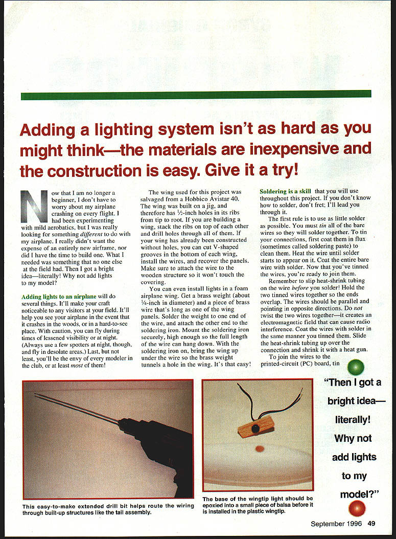
- To route wiring through built-up structures (tail assembly, fuselage, or wing), an easy method is to make a simple tunneling tool:
- Get a piece of brass wire long enough to reach through the structure and a small brass weight (about 1/8-inch diameter).
- Solder the weight to one end of the wire and attach the other end to a soldering iron so the weight can hang down freely.
- Turn the iron on and bring the wing or foam up under the hot weight; the brass weight will tunnel a hole through the foam or balsa. Hold steady and go slowly.
- An extended-shaft drill bit is also useful for drilling tunnels through built-up tail or fuselage structures. You can use a piece of Nylrod (pushrod tubing) or similar in the drill to help start and guide a tunnel.
Wingtip lights — installation
- Remove the plastic wingtip (if present) by cutting the tape around its edges.
- Mark a drill hole about 7/8 of the way back in the center of the plastic wingtip (or about halfway back depending on your lights and wingtip shape).
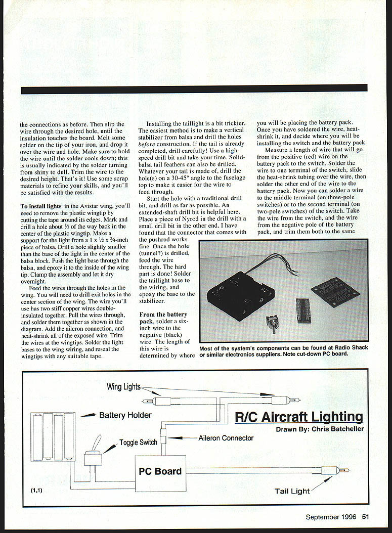
- Make a support from a 1 x 1/2 x 3/4-inch piece of balsa. Drill a hole slightly smaller than the base of the light in the center of the balsa block.
- Push the light base through the balsa and epoxy it to the inside of the plastic wingtip. Clamp and let the epoxy cure overnight.
- Drill exit holes in the wing center section for the wiring, and feed the double-insulated wires (two stiff copper conductors) through the wing.
- Pull the wires through and solder connections as required. Add the aileron connector and heat-shrink any exposed wire.
- Trim the wires at the wingtips and solder the light bases to the wing wiring.
- Reseal the wingtips with suitable tape.
Note: When slipping a wire into the wingtip light base, strip the insulation until the bare wire will contact the base pad. Melt some solder on the iron tip and drop it over the wire hole to secure the wire; hold the wire until the solder cools (it will go from shiny to dull). Trim the wire to the desired height.
Taillight — installation
Installing the taillight is trickier but straightforward if planned.
- If possible, build the vertical stabilizer from balsa and drill the holes before final construction.
- If the tail is already completed, drill carefully with a high-speed drill bit and take your time. Solid-balsa tail feathers can also be drilled.
- Drill the hole(s) at a 30°–45° angle to the top of the fuselage to make feeding the wire easier.
- Start the hole with a regular drill bit and drill as far as possible. An extended-shaft drill bit and using a piece of Nylrod or pushrod tubing as a guide can help complete the tunnel.
- Feed the wire through the tunnel. Solder the taillight base to the wiring and epoxy the base to the stabilizer.
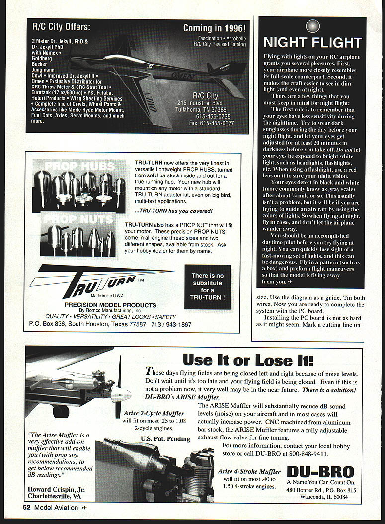
Wiring, switch, battery, and PC board
- From the battery pack, solder a six-inch wire to the negative (black) lead. The length can be adjusted depending on battery-pack placement. Heat-shrink the connection.
- Measure and cut a wire from the positive (red) lead on the battery pack to the switch. Solder it to one terminal of the switch, slide on heat-shrink tubing, then solder the other end to the battery pack.
- For the remaining switch terminal: solder a wire to the middle terminal (on three-pole switches) or the second terminal (on two-pole switches). This wire will go to the PC board.
- Trim the wire from the switch and the negative lead to the same length and solder them to the appropriate pads on the PC board.
- Cut the PC board to size (band saw or score and snap), and sand the edges smooth with 100-grit sandpaper. Tin the pads on the board.
- Push the tinned wires from the taillight into the first set of holes and solder them. Next insert the battery-pack wires and solder them. In the last set of holes solder the wing-light wires. Snip excess wire; the height above the board should be about 1/8 inch.
- If the PC board copper outlines for positive or negative rails are not continuous, you may need to solder small metal tabs or short lengths of stripped stiff wire to connect them: tin the stiff wire, hold it against the board, and melt solder over it to bond it in place. Trim excess.
Mounting and testing
- Mount the switch and wrap the battery pack in foam for vibration protection. Secure the battery pack in the fuselage.
- Try the system: the taillight should be clear white; as viewed from the rear, a green light should be in the right wingtip and a red light in the left wingtip. These color differences are important for orientation.
Cautions and notes
- Use spotters when flying in low visibility or desolate areas; do not fly at night unless properly certified and legal.
- Flasher lights common in Christmas-light sets are not recommended with glow engines—engine interference can dim the flasher by about 50%. They are more suitable for electric models.
- Complexity adds weight; any added weight affects flight characteristics. Plan placement and minimize unnecessary weight.
- You can expand on this idea: string lights in wing bays and cover with clear film, add landing or taxi lights (clear or halogen), install strobes with a flasher circuit, even spell out words with strings of lights.
- If you need reflectors, use aluminum foil or miniature mirrors.
Parts List
- 3 lights and bases (1 red, 1 green, 1 clear/white)
- 10 (or more) feet of copper wire with double insulation
- Heat-shrink tubing (Radio Shack part number 278-1627A recommended)
- 1 toggle switch (Radio Shack part number 275-612 recommended)
- 1 AA battery holder (Radio Shack part number 270-391 recommended)
- 1 PC board (Radio Shack part number 276-159 recommended)
- 1 aileron connector
- Epoxy
- 3 inches of 1/2 x 3/4-inch soft or medium balsa
Have fun—go wild! The possibilities are endless; this is just a starting point.
Transcribed from original scans by AI. Minor OCR errors may remain.

