

Airfoils for Flying Wings
By Barnaby Wainfan
How to choose suitable airfoils for tailless models
With the advent of the latest Northrop flying wing (the B-2 Stealth bomber) I expect there will be a revival of interest in flying wings and tailless airplanes. Unfortunately, I also expect 40-year-old mistakes to be repeated as people attempt to rediscover how to design flying wings.
I have been developing and campaigning tailless models for many years. Many are now competitive with or superior to conventional models in their class. The flying wing configuration is well worth investigating, but it is important to do it right.
When people discuss flying wings there is a lot of ballyhoo about the concept of stable airfoils. Reflexed airfoils (discussed later) are usually held up as examples of these magic "stable airfoils." There is no such thing as a stable airfoil! Nor is there such a thing as an unstable airfoil, for that matter.
The stability of an airplane depends on the relative positions of the center of gravity and the aerodynamic center and is not dependent on the shape of the airfoil. The notion of a stable airfoil was one of the many misconceptions caused by the use of the archaic idea of an airfoil center of pressure. Noted aerodynamicist Irv Culver had the last word on this antiquated idea when he stated: "The concept of center of pressure was invented by the manufacturers of oxcarts to prevent the manufacture of aircraft."
The one kernel of truth in the notion of stable airfoils is that a stable, unswept, tailless airplane must have an airfoil with a positive pitching moment to trim out the nose-down moment produced by putting the center of gravity ahead of the aerodynamic center as required for stability.
Although the stable airfoil is a myth, there is a difference between the types of airfoils suitable for tailless and conventional airplanes. A very common mistake among designers of tailless models is to use unsuitable airfoils. An airfoil that is appropriate for a conventional airplane with a tail will not be right for a flying wing.
Pitching Moment
In addition to producing lift and drag, an airfoil generates a torque or pitching moment that twists the leading edge up or down. This moment is positive if it acts to raise the leading edge and negative if it acts to lower the leading edge.
One of the vital differences between tailless airplanes and conventional airplanes is that the pitching moment characteristics of the wing airfoil are far more important on a flying wing. For a stable airplane to trim, the airplane as a whole must have a positive aerodynamic pitching moment about its aerodynamic center. On conventional airplanes, this moment is provided by the tail. On tailless airplanes, the wing must produce the necessary moment to trim the airplane as well as providing the lift to support it.
The pitching moment generated by the airfoil is called the pitching moment about the aerodynamic center or the zero-lift pitching moment. It can be nondimensionalized in the same way as lift and drag are reduced to Cl and Cd to form a pitching moment coefficient (Cmac or Cm0).
The pitching moment about the aerodynamic center does not change as the angle of attack of the airfoil changes, as long as the airfoil is not stalled. The aerodynamic center is located at or very near the quarter-chord of the airfoil. To simplify things during this discussion I will simply refer to the pitching moment about the aerodynamic center as the pitching moment.
Effect of Camber on Pitching Moment
The pitching moment generated by the airfoil is determined almost entirely by the camber of the airfoil. Both the amount of camber and the distribution of camber have an effect.
In general, the more camber an airfoil has, the more negative its pitching moment will be. A symmetrical airfoil, which has no camber, has a zero Cm and generates no pitching moment at all. An airfoil with negative or inverted camber will generate a positive (nose-up) pitching moment.
The distribution of the camber of an airfoil has a dramatic effect on its pitching moment. Adding the same amount of camber at different points on the airfoil affects the pitching moment more or less depending on where on the chord the camber is added.
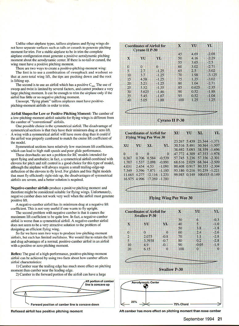
The more aft the position of the camber, the larger its effect on Cm0 will be. The aerodynamic center of the airfoil is at or near the 25% chord position. The lever arm of the leading edge about the aerodynamic center is 25% of the chord while the lever arm of the trailing edge is 75% chord. In other words, a camber change near the leading edge will have only one-third the lever arm of a camber change near the trailing edge. Because of this, a change in aft camber is roughly three times as effective at changing pitching moment as a change in camber near the nose of the airfoil.
Many of the "advanced airfoils" for general aviation that have appeared in the last 5–10 years have featured large amounts of aft camber. Such airfoils are also showing up on some RC gliders. Unfortunately, these aft-cambered airfoils also generate large negative pitching moments which make them entirely unsuitable for tailless airplanes.
The same is true of the thin, highly undercambered airfoils used on free flight rubber models. Even flat-bottomed airfoils like the old reliable Clark Y produce some negative pitching moment.
The result of using a negative-pitching-moment airfoil on a flying wing is poor performance and difficult trimming. The airplane must either have lots of sweep and washout or large up-deflected tips (or both) to have the positive pitching moment required to trim the airplane in flight.
Both of these approaches to trimming can produce high drag and poor performance. It is also difficult to get the amount of twist and/or tip deflection right the first time, and many flying wing models (particularly free flight models) are damaged before they can be successfully trimmed.
Low-Moment Airfoils
As the reader may have already inferred, the vast majority of airfoils produce a negative (nose-down) pitching moment. This is not surprising, since most airfoils have positive camber. For most types of airplane a moderate amount of negative pitching moment is acceptable. The tail or canard can easily generate enough pitching moment to trim the airplane.
Unlike other airplane types, tailless airplanes and flying wings do not have separate surfaces such as tails or canards to generate pitching moment for trim. For a stable airplane to be in trim the complete airplane configuration must generate a positive aerodynamic pitching moment about the aerodynamic center. If there is no tail or canard, the wing must have a positive pitching moment.
There are two ways to create a positive-pitching-moment wing:
- Use a combination of sweepback and washout so that at zero total wing lift, the tips are pushing down and the root is lifting up.
- Use an airfoil which has a positive Cm0. The use of sweep and twist is limited by several factors, and cannot produce a very large pitching moment. It can be enough to trim the airplane only if the airfoil has little or no negative pitching moment.
Unswept, “flying plank” tailless airplanes must have positive-pitching-moment airfoils in order to trim.
Airfoil Shapes for Low or Positive Pitching Moment
The camber of a low-pitching-moment airfoil suitable for flying wings is different from the camber of “conventional” airfoils.
One possible choice is the symmetrical airfoil. The disadvantage of symmetrical sections is that they have their minimum drag at zero lift. A wing with a symmetrical airfoil will have more drag than it could if the airfoil was properly cambered to match the cruise lift coefficient of the model.
Symmetrical sections have relatively low maximum lift coefficients, which can lead to high stall speeds and poor glide performance.
These drawbacks are not a problem for RC models intended for sport flying and aerobatics; in fact, a symmetrical airfoil combined with elevons for pitch and roll control is a good choice for this type of model, although the airplane will always require a small trailing-edge-up deflection of the elevons to fly level. For gliders and free flight models that must fly efficiently right-side up, the disadvantages of symmetrical airfoils are severe, and a better solution is required.
Negative-camber airfoils produce a positive pitching moment and therefore might be considered suitable for flying wings. Unfortunately, negative camber does not work very well when the airfoil must generate positive lift.
A negative-camber airfoil has its minimum drag at a negative lift coefficient. This is not very useful if one wants to fly upright.
The second problem with negative camber is that it causes the maximum lift coefficient to be quite low. In fact, a negative-camber airfoil is worse than a symmetrical airfoil. A negative-camber airfoil does not seem to be a very attractive solution to the problem of designing an efficient flying wing.
So far we have seen two ways to produce low-pitching-moment airfoils, but each has limited usefulness. We would like to retain the lift and drag advantages of a normal, positive-camber airfoil in an airfoil with a positive or zero pitching moment.
Reflex
The goal of a high-performance, positive-pitching-moment airfoil can be achieved by using two facts about how camber affects airfoil characteristics:
- Camber near the trailing edge has much more effect on pitching moment than camber near the leading edge.
- Camber in the forward portion of the airfoil can have a large positive effect on the maximum lift of an airfoil and can move the minimum drag to a positive lift coefficient.
Using these two concepts we arrive at the proper camber distribution for a high-performance, positive- or zero-pitching-moment airfoil suitable for use on a flying wing. The airfoil should have positive camber over its forward portion to provide good lift and drag characteristics, and negative camber over its aft portion to control its pitching moment.
In such an airfoil the forward portion of the camber line is concave down while the aft portion of the camber line is concave up. The mathematical term for a curvature reversal of this type is a reflex, so this type of airfoil is said to have reflex camber. Usually it is just called a reflexed airfoil and the term "reflex" is used to describe the amount of upsweep in the aft portion of the airfoil.
The amount of reflex required is determined by the desired pitching moment and the amount of positive camber in the forward portion of the airfoil. Reflexed airfoils can have positive pitching moments and good lift and drag characteristics.
In general, they still tend to have somewhat lower maximum lift coefficients than conventionally cambered airfoils, but not so low as to render them unacceptable for many flying wing applications.
Some Good Flying Wing Airfoils
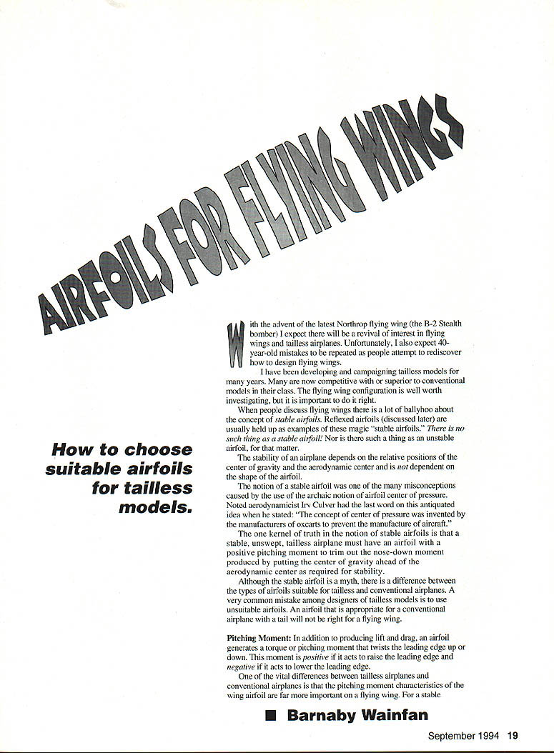
- The Cyrano II P-30 airfoil is for a constant-chord "plank" tailless P-30 model. The prototype won Open P-30 at the 1984 Reno Nats; plans were published in the December 1986 Model Aviation and are still available. The Cyrano airfoil is a good all-around free-flight flying wing airfoil. I have used it successfully on rubber models, gas models and on an RC HLG. This model climbs beautifully, but does not penetrate well.
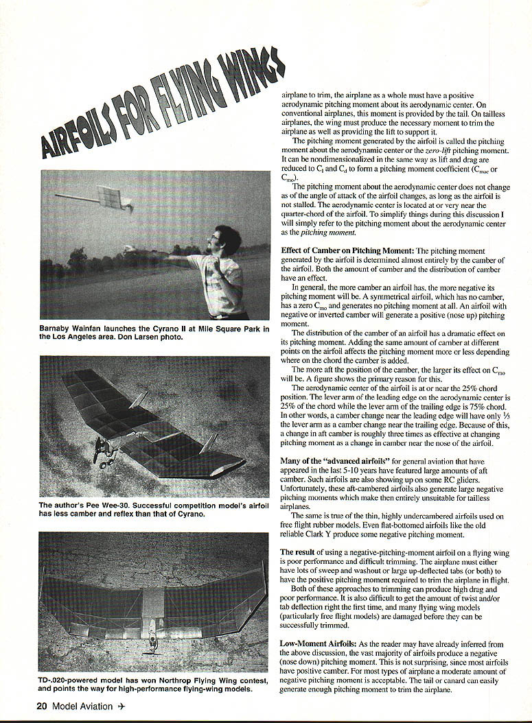
- Airfoil used in Pee Wee 30: This airfoil was used on my Pee Wee 30 gas model, which won the 1987 Orbiters Annual. The model is certainly competitive with the conventional models and may well be superior. The airfoil is nearly flat-bottomed and is intended for fast-climbing gas models or burst-climber rubber models. I think it would also work well on an RC HLG.
- The Swallow P-30 airfoil: This airfoil has a lot more camber than the other two. It is excellent for slow floaters. I have used it successfully on cruise-climbing rubber models and on towline gliders. It is not appropriate for gas models because the large undercamber in the forward portion will hurt climb performance. This airfoil gives the best glide performance of the three presented here.
- Airfoils for tailless R/C sailplanes: An excellent series of airfoils for tailless glider flying wings has been developed by Dave Jones of Western Plan Service. Coordinates are available, along with plans for Dave's excellent Raven and other flying wing models, from Western Plan Service, 5621 Michelle Drive, Torrance, CA 90503.
Transcribed from original scans by AI. Minor OCR errors may remain.

