
Airmaster
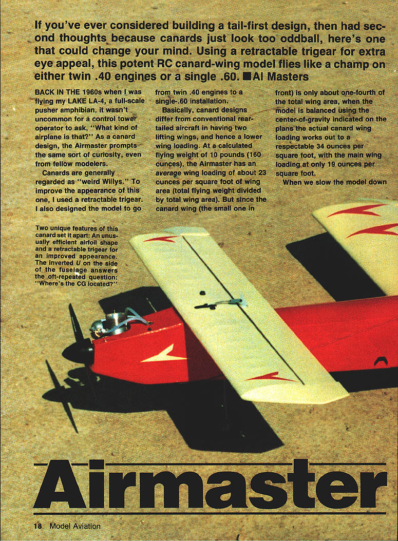
If you've ever considered building a tail-first design but balked because canards look odd, the Airmaster may change your mind. With a retractable trigear for appeal, this canard-wing RC model flies well as either twin .40s or a single .60. — AL Masters
Background
- I drew inspiration from flying a full-scale pusher amphibian (LAKE LA-4) in the 1960s; canards draw curiosity from fellow pilots and controllers.
- Canards are often regarded as "weird," so I fitted a retractable trigear and designed the airframe to accept either twin .40 engines or a single .60 to broaden appeal and utility.
- Test flying determines the desirable center-of-gravity (CG). CG behavior can be unpredictable—historically, Dr. Heinrich Focke died experimenting with CG on the Focke-Wulf 19A. On my first prototype test, with twin .40s at full throttle, the model performed a tight loop immediately after liftoff; power was cut and the model landed without damage.
Design and Aerodynamics
- Canard configuration: two lifting wings produces lower overall wing loading.
- Calculated flying weight: 10 lb (160 oz).
- Average wing loading: ~23 oz/ft² (total flying weight ÷ total wing area).
- Canard (front) area ≈ one-fourth of total wing area:
- Canard wing loading ≈ 34 oz/ft².
- Main wing loading ≈ 19 oz/ft².
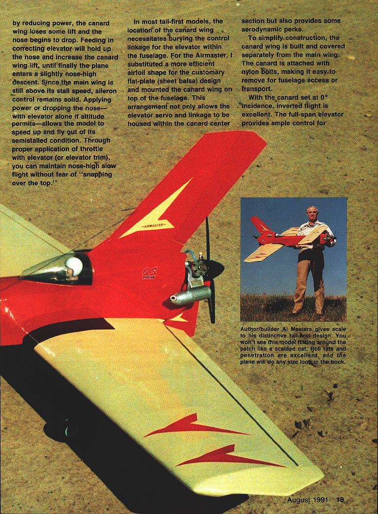
- Flight characteristics:
- When speed is reduced, the canard loses lift first and the nose drops. Applying up elevator increases canard lift; the model may enter a slightly nose-high descent while the main wing remains above stall, retaining aileron control.
- Recover by applying throttle or dropping the nose (or both). Proper throttle and elevator trim allow nose-high slow flight without "snapping over the top."
- With canard set at 0° incidence, inverted flight and outside loops are good; full-span elevator gives solid control.
- Layout choices:
- Canard mounted on top of the fuselage allows elevator servo and linkages to live inside the canard center section and enables an efficient airfoil rather than a flat-plate canard.
- Canard built and covered separately; attached with nylon bolts for easy removal.
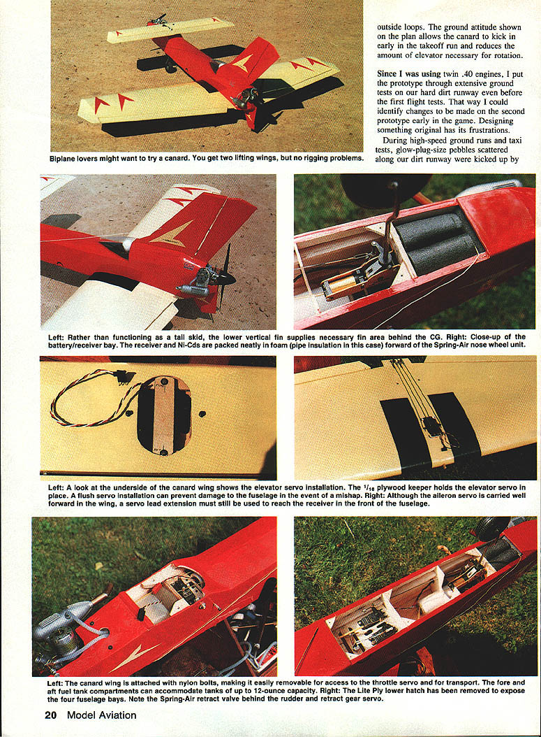
Major Features
- Retractable trigear (retracts for appearance).
- Configurable engine installations:
- Twin .40s (tractor front / pusher rear).
- Single .60 (pusher).
- Firewalls accept .40 or .60 engines; blind nuts provided for both sizes.
- Rugged construction with reinforced fin / rudder supports for pusher installations.
- Optional tip fins (tested then removed without adverse directional stability effects).
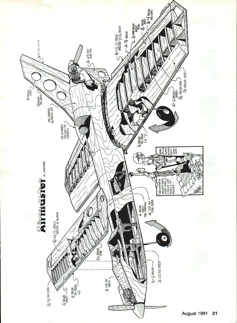
Construction Overview
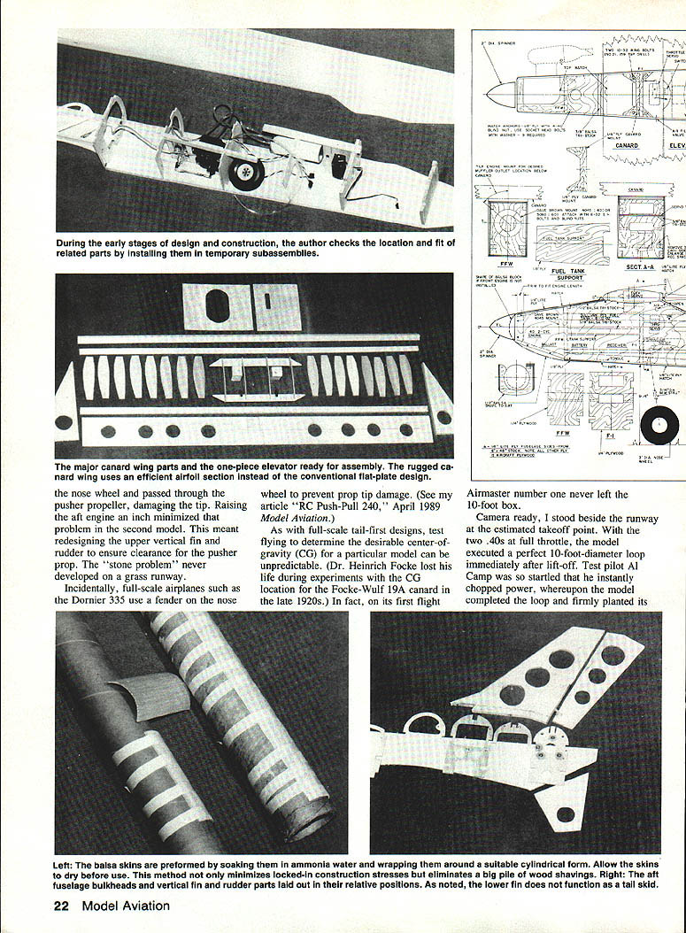
Note: The following condenses the key construction steps and critical dimensions called out in the plans. Refer to full-size plans (page 204) for complete details.
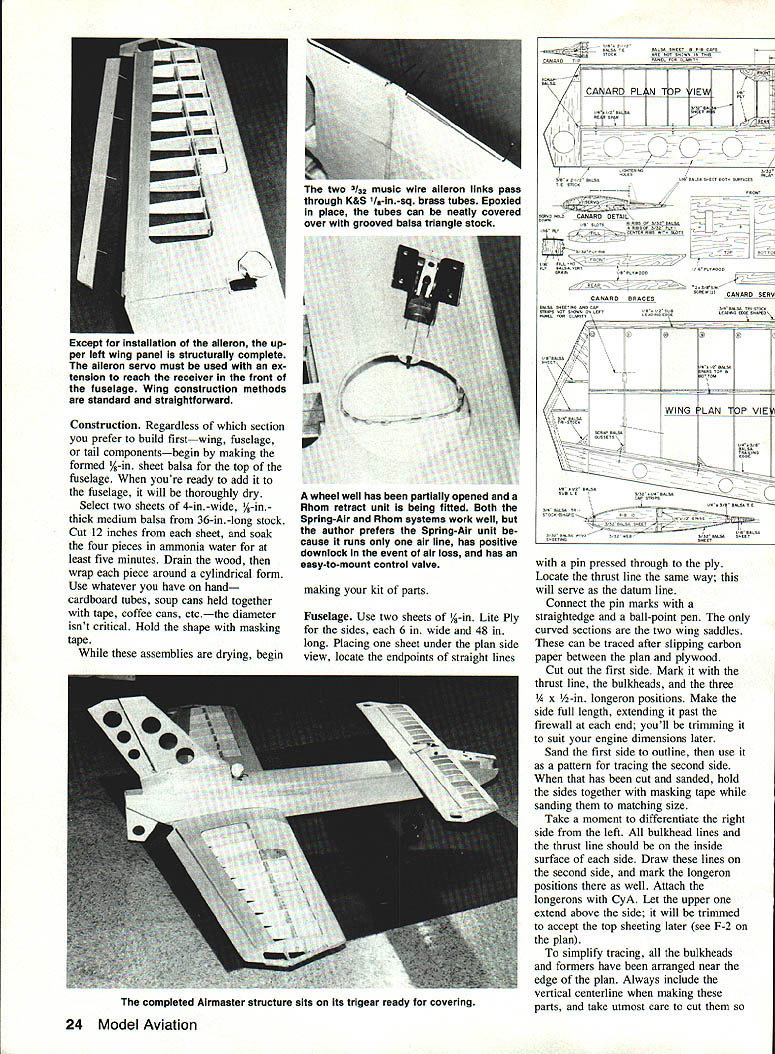
Preparing top sheeting
- Make formed 1/8" sheet balsa for the fuselage top:
- Two sheets, 4" wide x 1/8" thick from 36" stock; cut 12" from each.
- Soak pieces in ammonia water ~5 minutes, drain and wrap around a cylindrical form; hold with masking tape until dry.
Fuselage
- Sides:
- Use two 1/8" Lite Ply sheets, 6" × 48".
- Transfer thrust line and bulkhead locations from the plan; cut and sand one side and use it as pattern for the other.
- Longerons: attach with CYA; upper longeron extends above side to accept top sheeting later.
- Bulkheads and formers: include vertical centerline on each part; ensure accurate fit so sides remain parallel and bottoms are square.
- Slots for fin supports in F-7, F-8, and aft firewall must be precise; test-fit 3/8" balsa sheet for vertical fin.
- Engine selection and mount:
- If twin configuration and engines differ, put heaviest in tractor (front) position.
- Mount and align engine to thrust line; mark and install blind nuts on firewalls.
- Nose wheel:
- Position retract on F-1 and secure with blind nuts. A fixed Fults RF-500 unit can substitute for retracts.
- Assembly:
- Epoxy front firewall in place using F-5 as spacer, epoxy aft firewall in place, clamp until cured.
- Fit remaining bulkheads, verify alignment, lock parts with CYA, then double-glue F-1 and F-5 with epoxy.
- Push fin supports in position, epoxy at bulkhead contact points.
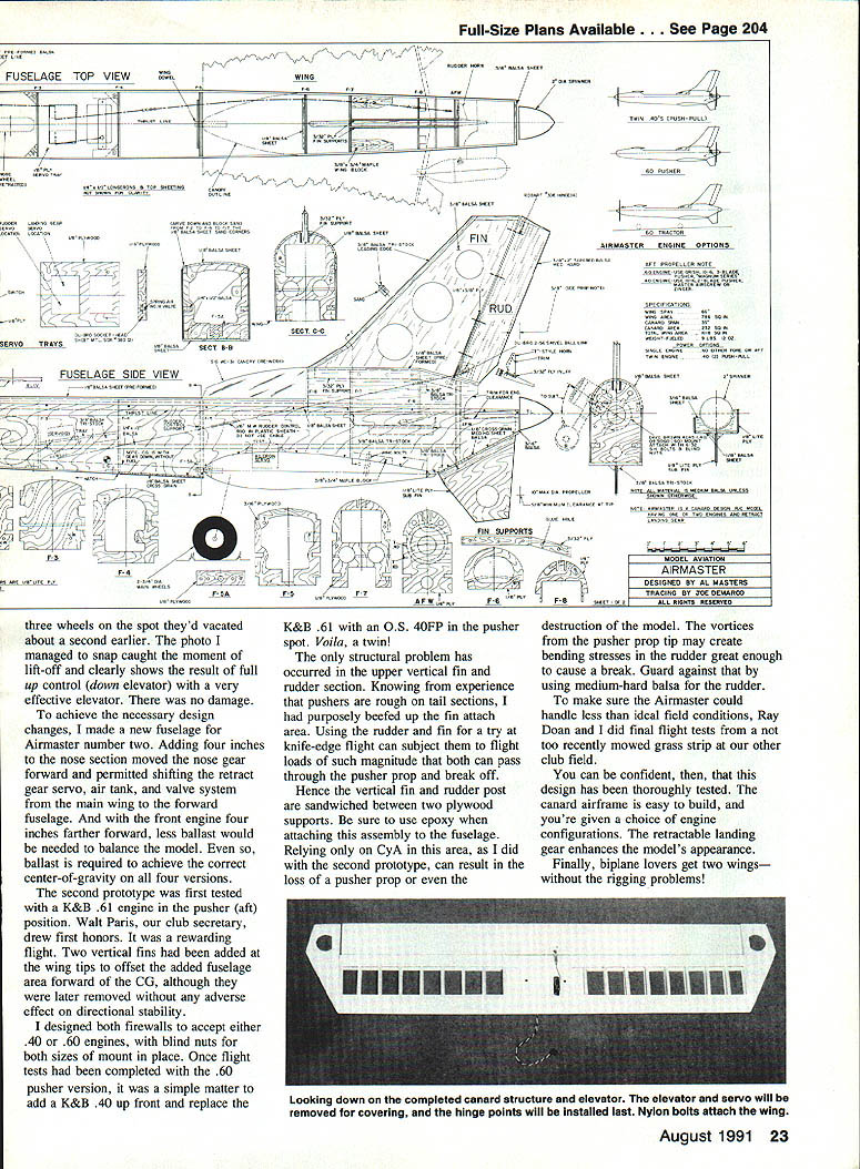
Canard
- Build over plan on waxed paper.
- Pin 1/4 × 1/2" rear spar and 1/2 × 1/8" sub-leading edge over the plan.
- Install 3/32" balsa sheet ribs; fit (do not glue) 1/8" plywood braces into the slotted center ribs.
- Top and bottom 1/16" plywood center sections: select grain as shown on plan to allow forming.
- Drill two 1/16" pilot holes in bottom center section for canard bolts; accurate center-to-center dimension matters for servo clearance.
- Add vertical-grain hard balsa fill blocks, top plywood, drill through with No. 21 and then No. 21 to No. 21? — (plans call for final holes with No. 21 pilot then No. 21?); final bolt hole is .159 (No.21) and later enlarge to No.21 front/back? — follow plan drill sizes shown.
- Complete canard: top/bottom sheeting, rib caps, 1/8" triangle leading edge. Tapered elevator stock used for canard tips.
Elevator
- Cut from 3/32" × 1/2" elevator stock; cut lightening holes.
- Drill 1/16" holes for Robart hinge points; drill matching holes through canard rear spar.
- Remove top material to accept 3/32" plywood insert for top-mounted control horn.
- Add 1/16" balsa sheeting to both sides; hinge points installed after covering.
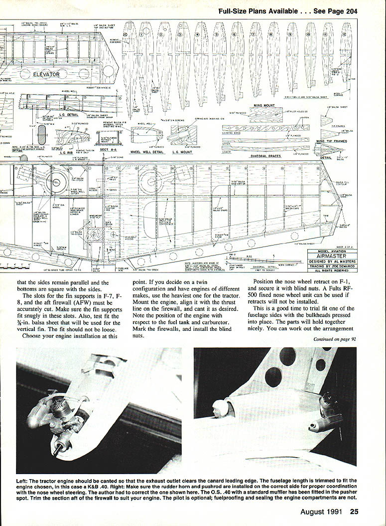
Wing
- Ribs: trace and cut one set, use as template for the other; sand in pairs.
- Spars: 1/4 × 1/2" balsa spars, cut to length.
- Dihedral braces and rib doublers from plywood; make left and right doublers.
- Glue rib doublers, drill for retract arm lines.
- If no retracts, use fixed-wire gear mounted to plywood doublers or formed aluminum gear.
- Build panels:
- Pin lower spar assembly over plan; position ribs 1–12; glue spar, sub-leading edge, and trailing edge.
- Add 3/32" balsa TE sheet, hinge supports, and vertical-grain web between ribs 1 and 12.
- Build second panel similarly.
- Join panels using 1/8" plywood dihedral braces and appropriate dihedral spacing (first panel elevated 2-1/4" as shown on plan). Glue all joints with CyA.
- Wing mount:
- Add plywood wing mount flush with top of ribs 1 and 1C, bolster with 1/2" triangle stock.
- Use soft balsa blocks drilled for bolt access (1/2" blocks, 3/16" holes).
- Make/fit main gear retract mounts (Rhom-Air or Spring-Air are acceptable).
- Main gear struts: 5/32" wire.
- Wheel wells: template and cut bottom sheeting for clearance, reinforce with 1/8" scrap balsa as indicated.
- Finish: tips, leading edge, rib caps, and center section sheeting. Open wing bolt access holes and true up.
Ailerons
- Cores from 3/8" × 1-1/2" aileron stock; add 1/16" light balsa sheet.
- Drill hinge pin holes with 7/64" bit; drill 3/32" hole for torque rod.
- Transfer hinge locations to wing; epoxy brass tubes on wing trailing edge for hinge pins.
- Remove ailerons for final sanding and covering.
Final Assembly and Fuselage Completion
- Sand wing saddle and fit wing to fuselage; ensure both sides meet wing at same angle.
- Epoxy wing hold-down blocks and clamp until cured.
- Drill pilot hole at leading-edge centerline, ream to 3/16" for wing dowel; assemble F-5A over dowel for adjustable mount.
- Drill and tap hardwood blocks for 1/4-20 wing bolts; redrill to 1/4" as required.
- Carve middle longeron in battery/receiver bay per plan; add fuel tank supports, servos, and radio tray.
- Epoxy 1/4" plywood canard mount; use canard to drill holes and tap for 10-32 nylon wing bolts; ream canard bolt holes to 3/16" for the dowel.
- Apply vaseline to dowel hole, insert 5/16" dowel for epoxy assembly of F-5A, then remove dowel from wing after epoxy cures (dowel to be epoxied into wing after covering).
- Add nose top sheeting, trim and shape longerons for smooth curve; fit aft sheeting—compound curves may require soaking or steaming sheet balsa.
- Fit fuselage bottom sheeting, tailcone fillets, tail skid plate with 1/32" plywood doublers.
- Install Spring-Air nose wheel or chosen unit; fit radio gear, Ni-Cads in foam-lined compartment forward.
Reinforcements and Critical Details
- Upper vertical fin and rudder:
- Pushers cause extra stress. Sandwich the rudder/fin post between two plywood supports and use epoxy to attach to fuselage—do not rely only on CYA.
- Use medium-hard balsa for rudder to resist prop-tip vortex-induced bending.
- Knife-edge or high-load maneuvers can break the fin or rudder if not reinforced.
- Hinges: treat hinge centers with petroleum jelly before epoxying hinge points to prevent loss of hinge action after epoxy cures.
- Fuelproof and seal engine compartments.
Engine, Propeller, Muffler and Related Notes
- Engine options:
- Twin .40s (tractor/pusher combination).
- Single .60 in pusher position.
- Ballast required for CG:
- Twin .40s: about 9 oz of ballast in nose area (with gear down).
- Single .60 pusher: 1–2 lb lead up front to rebalance (relocating Ni-Cads, receiver, and gear servo rearward can reduce ballast required).
- Mufflers:
- Prefer routing aft engine muffler exhaust rearward; some muffler outlets can be sawn at 45° to direct exhaust.
- O.S. .40 muffler outlet can be rotated for exhaust direction; muffler styles exist for O.S. .40 and HB .40 in pusher installation.
- Propeller guidance:
- Pusher prop must not exceed 10" diameter due to rudder / lower fin location.
- Avoid highly flexible pusher props with a .60 in the aft spot.
- Recommended: three-bladed Grish Magnum series for larger-power absorption without damage.
Ground Testing and Field Notes
- Hard dirt runway testing revealed pebble damage to pusher prop tips: nose wheel occasionally passed through pusher prop wake and struck tips.
- Solution: raise aft engine ~1/8" (one-eighth inch) on the second prototype and redesign upper vertical fin/rudder for clearance.
- Problem did not occur on grass strips.
- Full-size reference: Dornier 335 uses a fendered nose wheel to prevent prop-tip damage.
- Test and iterate early with ground runs to identify necessary changes before first flight.
Fuel Tank and Ballast Placement
- Aft fuel tank: after testing, place the tank clunk in the forward position with the clunk line as short as practical but flexible enough to reach the tank bottom.
- Avoid placing an aft fuel tank too low.
- Add ballast to achieve desired CG with gear down and before filling the fuel tank.
Radio, Control Linkages and Wiring
- Rudder control:
- Use 1/16" music wire through Nyrod sheath; connect to rudder horn with Du-Bro 2-56 swivel ball linkage to prevent flutter-inducing play.
- Servo leads and removability:
- Use servo extensions for easy removal of canard and main wings.
- Extend leads by cutting and soldering stranded extension wire; insulate solder joints with heat-shrink tubing.
- Choked extensions were not necessary with FM or PCM systems on prototypes.
- Muffler and exhaust routing, plus fuelproofing, are important prior to flight.
Flying Characteristics
- The Airmaster is predictable and stable when trimmed properly.
- Retract gear for appearance—looks great.
- Both twin .40 and single .60 installations produce an assertive, well-mannered flier with good roll rate and penetration.
- Aerobatics:
- Performs loops of all sizes, good outside loops, and maintains control if one engine stops.
- At reduced power with elevator full up the model can appear to hover with near-zero forward speed; no sharp stall experienced in testing.
- Landing:
- Nose-high approaches are acceptable; aileron control remains effective to touchdown.
- Feed a little throttle on final to reduce descent rate before running out of elevator.
- CG changes:
- Move CG gradually when experimenting—rearward shifts can change the model from stable to twitchy to uncontrollable.
Final Remarks
- The canard airframe is straightforward to build and offers engine configuration choices.
- Retractable landing gear, clean lines, and the two-wing layout will please biplane lovers—without rigging.
- Full-size plans available (page 204).
- Always fuelproof engine compartments, reinforce critical fin/hinge areas with epoxy, and conduct thorough ground testing before first flight.
Transcribed from original scans by AI. Minor OCR errors may remain.

