
Airmaster Peanut
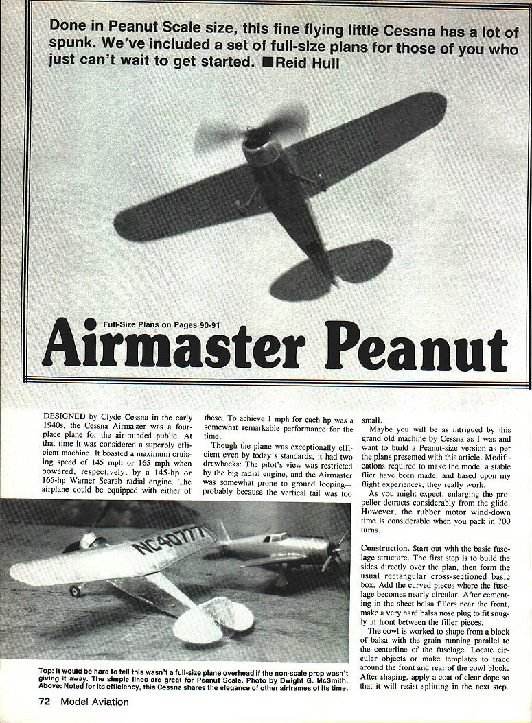
Done in Peanut Scale size, this fine flying little Cessna has a lot of spunk. We've included a set of full-size plans for those of you who just can't wait to get started. — Reid Hull
Overview / History
Designed by Clyde Cessna in the early 1940s, the Cessna Airmaster was a four-place plane for the air-minded public. At that time it was considered a superbly efficient machine. It boasted a maximum cruising speed of 145 mph or 165 mph when powered by, respectively, a 145-hp or 165-hp Warner Scarab radial engine. The airplane could be equipped with either of these. To achieve roughly 1 mph per hp was a notable performance for the time.
Though exceptionally efficient even by today's standards, the Airmaster had two drawbacks: the pilot's view was restricted by the big radial engine, and the Airmaster was somewhat prone to ground-looping—probably because the vertical tail was too small.
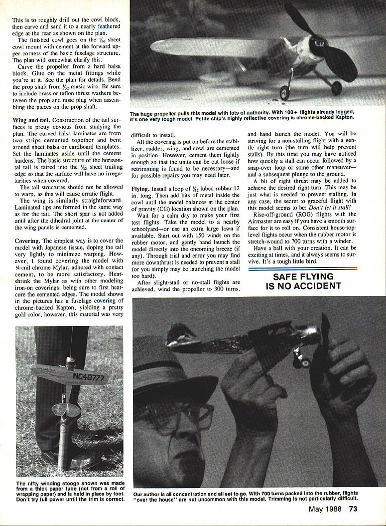
If you’re intrigued by this grand old machine, the plans presented here will let you build a Peanut-size version. Modifications to make the model a stable flier have been incorporated, and based upon flight experience, they work well. Enlarging the propeller will detract from glide, but the rubber motor wind-down time is considerable when you pack in 700 turns.
Construction
Fuselage
- Start with the basic fuselage structure. Build the sides directly over the plan, then form the usual rectangular cross-section basic box.
- Add the curved pieces where the fuselage becomes nearly circular.
- Cement in the sheet balsa fillers near the front.
- Make a very hard balsa nose plug to fit snugly in front between the filler pieces.
Cowl and Nose Plug
- Work the cowl to shape from a block of balsa with the grain running parallel to the centerline of the fuselage.
- Locate circular objects or make templates to trace the front and rear outlines of the cowl block.
- After shaping, apply a coat of clear dope so the wood will resist splitting during the next step.
- Drill out the cowl block and carve and sand nearly to a feathered edge at the rear as shown on the plan. The finished cowl is one piece.
- Cement a 1/16" sheet cowl mount forward up to the upper corners of the basic fuselage structure (the plan clarifies the exact placement).
Propeller and Shaft
- Carve the propeller from a hard balsa block.
- Glue in the metal fittings as shown on the plan.
- Bend the prop shaft from 1/32" music wire.
- Include brass or Teflon thrust washers between the prop and the nose plug when assembling the prop-shaft pieces.
Wing and Tail Construction
Tail Surfaces
- Tail construction is straightforward from the plan.
- Curved balsa laminates are formed from two strips cemented together and bent around sheet balsa or cardboard templates. Set the laminates aside until the cement hardens.
- The basic structure of the horizontal tail is faired with 1/32" sheet trailing edge so the surface will have no irregularities when covered.
- Allow tail structures to dry thoroughly; warp will cause erratic flight.
Wing
- The wing is similarly straightforward. Form laminated tips the same way as for the tail.
- Do not add the short spar until after the dihedral joint and the center wing panels are cemented.
- Note the plan callouts: 1/32" ribs, 1/16" x 1/8" leading edge, 1/16" square spars, and 1/8" x 1/16" trailing edge. The left tip includes 3° washout.
Covering
- The simplest covering is Japanese tissue; dope the tail very lightly to minimize warping.
- Another satisfactory covering is 1/4-mil chrome Mylar adhered with contact cement. Heat-shrink Mylar and other iron-on coverings can be used—be sure to first heat-cure cemented edges.
- The model pictured used chrome-backed Kapton for a gold fuselage finish; however, this material is difficult to install.
- Apply all covering before cementing the stabilizer, rudder, wing, and cowl into position. Cement lightly enough so these units can be cut loose for retrimming or repairs if necessary.
Flying
Power and Balance
- Install a loop of rubber for power. The plan shows a 12" long loop of 3/32" rubber strip; a loop about 1/8" (or the plan-specified 3/32") and 12" long is recommended.
- Add bits of metal inside the cowl until the model balances at the center of gravity (CG) location shown on the plan.
Test Flights and Trim
- Wait for a calm day for first tests. Use a nearby schoolyard or a very large lawn.
- Start with 150 winds on the rubber motor and gently hand-launch the model into the oncoming breeze.
- Through trial and error, you may find downthrust is needed to prevent a stall (or you may be launching too hard). After achieving slight-stall or no-stall flights, increase to about 300 turns for hand launches that result in non-stalling flights.
- A gentle right turn will help prevent stalls. A bit of right thrust can be added to achieve the desired right turn and reduce stalling tendency.
- The key to graceful flight with this model is: don't let it stall. Stalls can quickly lead to a snap-over loop or other maneuvers followed by a plunge to the ground.
Rise-Off-Ground (ROG)
- ROG flights are easy if you have a smooth surface for the model to roll on.
- Consistent house-top-level flights occur when the rubber motor is wound to about 700 turns using a winder.
- The model is a tough little bird and generally survives spirited flying.
Plans and Component Notes
Plan Labels and Notes (as shown on drawing)
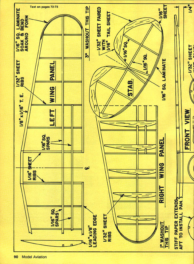
- LEFT WING PANEL
- 1/16" sq. laminate bend & form
- 1/32" sheet ribs
- 1/16" x 1/8" leading edge
- 1/16" sq. spars
- 1/8" x 1/16" trailing edge
- 1/16" sheet ribs
- 3° washout this tip
- RIGHT WING PANEL
- 1/32" ribs
- 1/16" x 1/8" leading edge
- 1/16" sq. spars
- STABILIZER (STAB.)
- 1/32" sheet faired with 1/16" tail sheet
- 1/16" sq. laminate
- 1/16" sq.
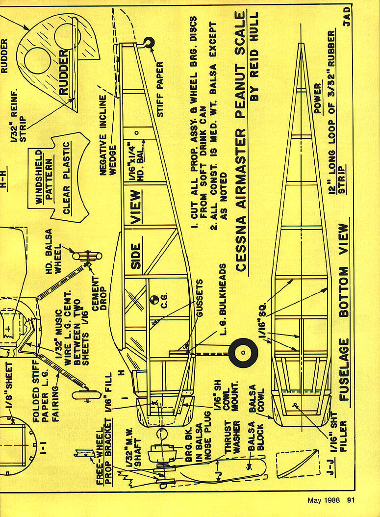
- FRONT VIEW: stiff paper extends aft to install panel.
- SIDE VIEW: 1/16" x 1/4" hd. bal.
- C.G. indicated on plan
- GUSSETS, L.G. BULKHEADS noted on plan
- FREE-WHEEL PROP. SHAFT: 1/32" music wire shaft
- BEARING BACKING, 1/8" balsa nose plug
- THRUST WASHER
- 1/16" sheet cowl mount
- BALSA cowl block
- 1/16" sheet filler
- HD. BALSA WHEEL
- PROP BRACKET: 1/32" music wire
- L.G. cement: wire between two sheets, 1/16" cement drop
- NEGATIVE INCLINE WEDGE
- STIFF PAPER
- RUDDER: 1/32" reinf. strip
- WINDSHIELD PATTERN: clear plastic
- FUSELAGE — BOTTOM VIEW: power — 12" long loop of 3/32" rubber strip
- 1/16" sq. (additional structure)
Construction Notes
- Cut all prop assembly and wheel bearing discs from soft drink can.
- All construction is medium-weight balsa except as noted.
(Plan details and component labels as shown on the drawing.)
Transcribed from original scans by AI. Minor OCR errors may remain.

