
AKRO BAT JR.
Design: Bill Winter Text: John Hunton
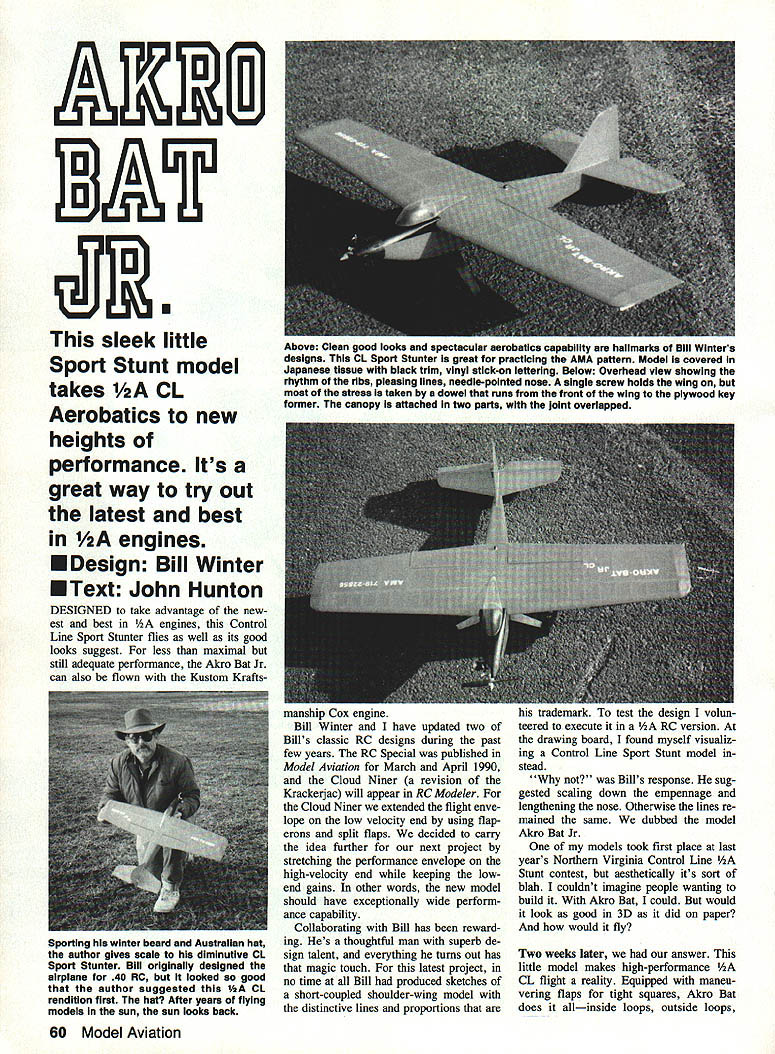
This sleek little Sport Stunt model takes 1/2A control-line aerobatics to new heights of performance. Designed to take advantage of the newest and best 1/2A engines, the Akro Bat Jr. flies as well as its good looks suggest. For less-than-maximal but still adequate performance, it can also be flown with a stock Cox engine with minor modifications.
Bill Winter and I have updated two of Bill's classic RC designs during the past few years. For our latest project we wanted a model with an exceptionally wide performance capability — good low-speed handling plus a high-velocity end of the flight envelope. Bill quickly produced sketches of a short-coupled, shoulder-wing model with his distinctive lines and proportions. We scaled down the empennage, lengthened the nose, and dubbed the model Akro Bat Jr.
Two weeks after the design was laid out we had our answer: the little model makes high-performance 1/2A control-line flight a reality. Equipped with maneuvering flaps for tight squares, Akro Bat Jr. does inside loops, outside loops and more, while retaining attractive, clean lines.
Construction
Akro Bat Jr. is unusually easy to build for two reasons:
- Accurate fuselage alignment is automatic once the plywood key former and landing-gear mounting plate are installed.
- Because the top spar is flat like the bottom spar, the continuous wing can be built flat on the workbench rather than in an airfoil jig.
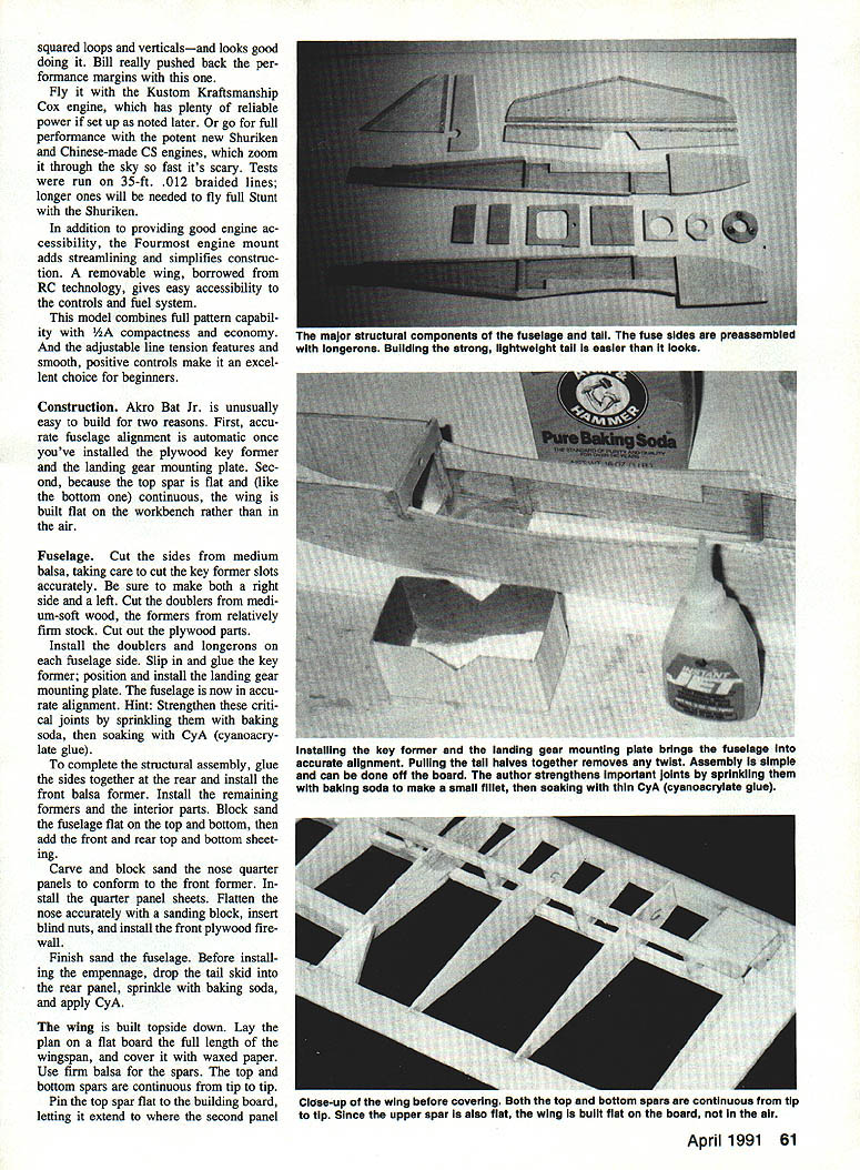
Fuselage
- Cut fuselage sides from medium balsa, taking care to cut the key-former slots accurately; make both right and left sides.
- Cut doublers from medium-soft wood and formers from relatively firm stock. Cut out plywood parts.
- Install doublers, longerons and fuselage sides. Slip-glue the plywood key former in position and install the landing-gear mounting plate; this ensures accurate alignment.
- Hint: Strengthen critical joints by sprinkling baking soda onto wetted cyanoacrylate (CYA) glue.
- Complete structural assembly; glue sides together at the rear and install the front balsa former. Install remaining formers and interior parts.
- Block-sand the fuselage flat on top and bottom; add front and rear top/bottom sheeting. Carve and block-sand the nose and quarter panels to conform to the front former. Flatten the nose accurately using a sanding block.
- Insert blind nuts and install the front plywood firewall.
- Before installing the empennage, prop the tail skid into the rear panel, sprinkle with baking soda, and apply CYA. Finish-sand the fuselage.
Wing
- The wing is built topside down. Lay the plan on a flat board the full length of the wingspan and cover it with waxed paper.
- Use firm balsa for the spars. The top and bottom spars are continuous from tip to tip.
- Pin the top spar flat to the building board, letting it extend to where the second panel joins. When the first panel is complete, remove the plan, spray it lightly with a release (WD-40 is often used) to make it easy to reverse, then reverse the plan and build the second panel over it.
- Add the top spar doubler. Cut out and position the ribs. Slip a support member onto the plan to support and align the ribs, and glue them to the spar.
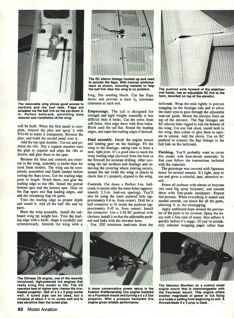
- Because the lines and controls are external to the wing, assembly is easier than for most stunt models. The wing can be completely assembled and finish-sanded before cutting the flaps loose.
- Cut the trailing-edge parts to length, notch them, and glue the trailing edge to the ribs. Install the partial bottom spar and the bottom spar. Glue on the flap spars and flap leading edges, and add remaining flap rib parts.
- Trim and install the leading edge. Add all the half ribs and tip parts.
- Sheet the wing assembly and install the outboard wing tip weight box. Trim the leading edge with a knife; shape it carefully and symmetrically. Smooth the wing with a long, flat sanding block.
- Cut the flaps loose and provide at least 1/32 in. minimum clearance at each end.
Empennage
- The tail is designed for strength and light weight. Cut the cores from soft balsa, then edge them with firm balsa.
- Block-sand the tail flat, round the leading edges and taper the trailing edges if desired.
Final assembly
- Install the engine mount and landing gear on the fuselage.
- Fit the wing to the fuselage, forming a neat, tight joint. Mark the wing leading-edge plywood from the hole in the firewall for accurate drilling.
- After covering the tail surfaces and fuselage and removing the covering where jointing occurs, mount the tail (with the wing in place) to check that it's properly aligned with the wing.
Controls
- Use a cut-down Perfect 3-in. bellcrank to access only the inner holes (approximately 2–3 in. lead-out spacing). Use the inner pushrod hole (about 0.6 in. from center).
- Drill for a ball connector to fit inside the pushrod (about 0.45 in. from center) and install the connector.
- Use a 2-56 RC pushrod with clevises; install so adjustable pushrod ends connect with the elevator horn.
- Use .020 in. minimum lead-outs from the bellcrank. Wrap the ends tightly to prevent snagging on the fuselage side and to allow the outer eyes to pass through the adjustable lead-out guide.
- Mount the elevator horn on top of the elevator.
- The flap linkages are RC aileron links rigged to exit the bottom of the wing. Cut one link short, install both in the wing, then solder or glue them to operate in the fuselage. Use an RC pushrod to connect the flap linkage to the ball link on the bellcrank.
Finishing
- Prime all surfaces with nitrate or butyrate dope (Sig spray butyrate was used on the prototype) and smooth with fine-grade sandpaper. Repeat until surfaces are sealed and smooth.
- Cut tissue for all parts, allowing 1/8 in. for overlapping.
- Apply unthinned dope around the perimeter of parts to be covered. Spray the tissue with a fine mist of water, then adhere it quickly before it becomes soggy.
- The prototype was covered with Japanese tissue because it is light, easy to use, and yields a colorful, taut finish.
- Lay the tissue in place, pulling out any noticeable wrinkles and sealing the edges with dope. Cover both sides of the part, dry thoroughly, then spray with clear dope for added strength.
- Spray or brush all parts with clear butyrate (use thinned dope for brushing). When the dope has dried completely, sand everything with fine paper. If you sand through the tissue, touch it up with a felt-tip pen of similar color.
- Apply additional coats of dope to strengthen and seal the surface. Add the AMA number and decoration.
- Use strong hinges and pin them for a secure grip.
Canopy
- Trim the canopy to fit the model. Cut it in two and attach the front half to the front fuselage and the rear half to the wing.
- Trim enough of the rear canopy to slip it into the front part. With the wing in place, glue on the canopy first at the front and then at the rear.
Rigging
Developing good stability and line tension depends on several factors:
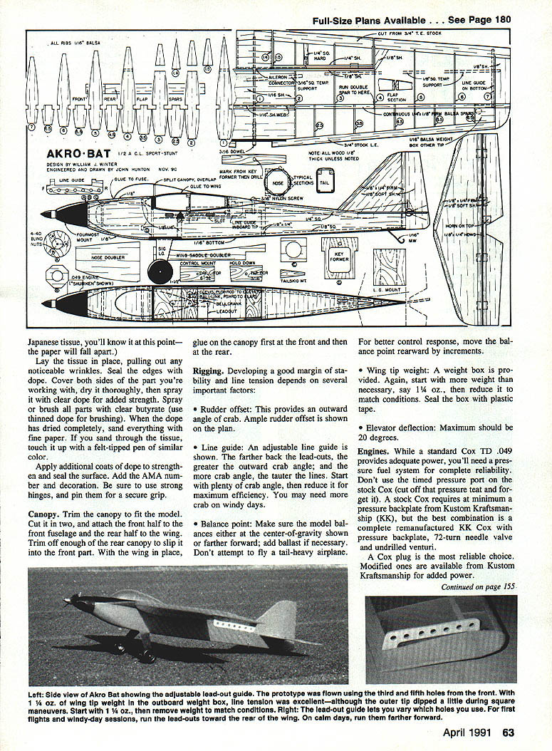
- Rudder offset: Provides an outward angle of crab. Ample rudder offset is shown on the plan.
- Line guide: An adjustable line guide is shown. The farther back the lead-outs, the greater the outward crab angle; more crab angle yields tauter lines. Start with plenty of crab angle, then reduce it for maximum efficiency. You may need more crab on windy days.
- Balance point: Make sure the model balances at the center-of-gravity shown or farther forward; add ballast if necessary. Do not attempt to fly a tail-heavy airplane. For better control response, move the balance point rearward in small increments.
- Wing tip weight: A weight box is provided. Start with more weight than necessary (for example, 1/4 oz.) then reduce it to match flying conditions. Seal the box with plastic tape.
- Elevator deflection: Maximum should be 20 degrees.
Engines
- A standard Cox TD .049 provides adequate power, but a pressure fuel system is recommended for reliability. Do not use the timed pressure port on the stock Cox; a stock Cox requires at minimum a pressure backplate from Kustom Kraftsmanship (KK).
- The best combination is a complete remanufactured KK Cox with pressure backplate, 72-turn needle valve and undrilled venturi. A Cox plug is the most reliable choice; modified plugs are available from Kustom Kraftsmanship for added power.
- The Shuriken (a Chinese-made engine) brings a new dimension of performance to 1/2A engines. It out-turns the Cox and is durable. The Shuriken fits into a modified Fourmost mount; use the smallest venturi option available. The Cox 5 × 3 prop works, but in an engine designed to operate at high rpm a thinned-blade 5 × 3 may work even better.
- A third option is the Chinese CS engine. Heavier than the Cox or Shuriken, the CS develops optimal power at higher rpm and requires a cut-down Cox 5 × 3 prop (perhaps to 4-1/2 in. diameter) and a pressure backplate. Use the sport version unless you want to fool with a tuned pipe.
Flying
- The 2-oz. fuel tank shown will sustain long flights. If you're new to flying, start with a half-filled tank.
- Position the model so it will break ground on the downwind side of the circle. Keep it low until you've built up enough speed to be certain the engine won't sag.
- Correct any tendency to bank in or out. Check that the rudder remains level in inverted flight.
- Once the model is fully trimmed, begin maneuvers. The AMA Precision Aerobatics routine is a good way to have fun while honing your flying skills.
Transcribed from original scans by AI. Minor OCR errors may remain.

