
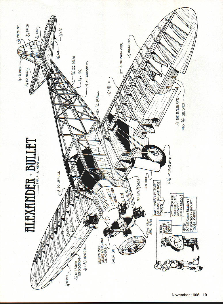
Alexander Bullet
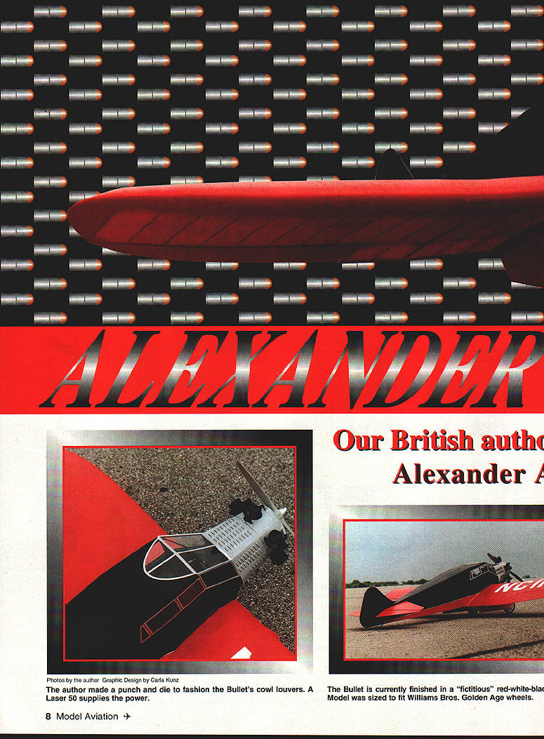
Photos by the author Graphic design by Carla Kunz
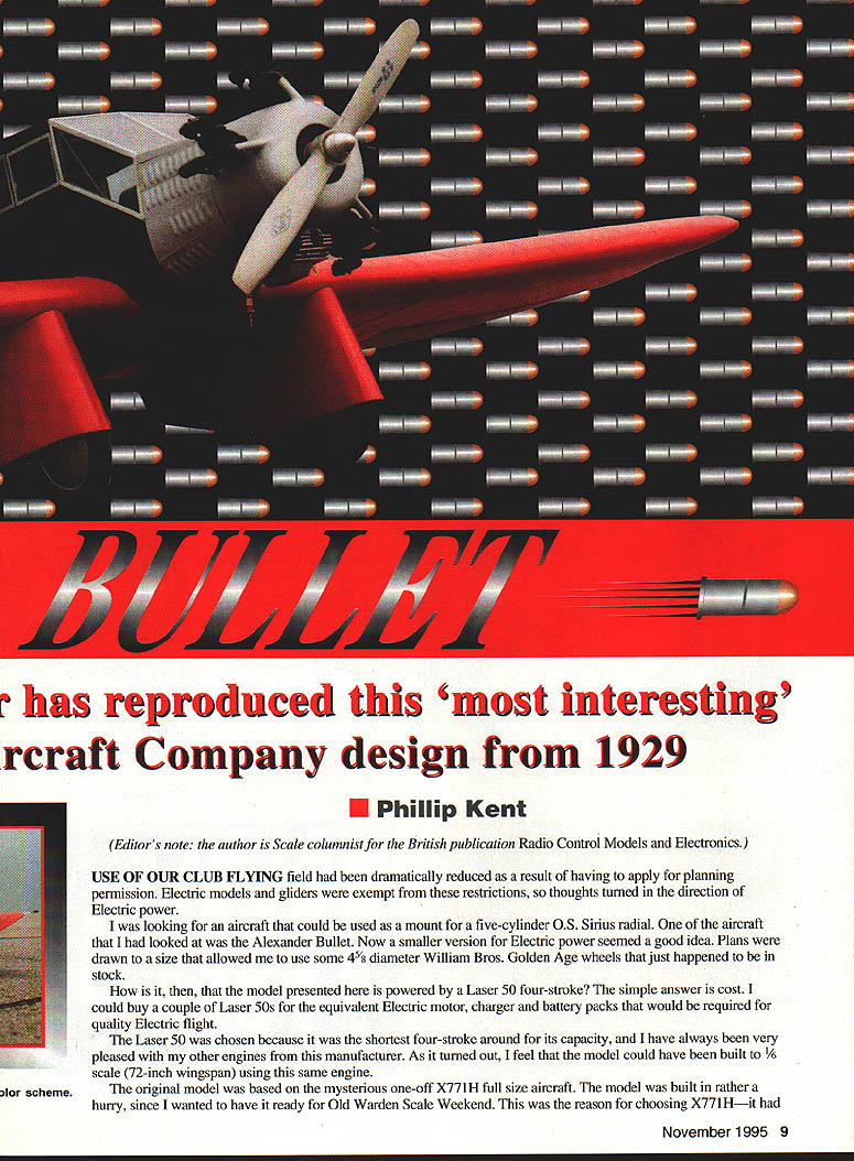
The Bullet is finished in a fictitious red–white–black scheme. A Laser .50 four-stroke supplies the power. The model was sized to fit Williams Bros. Golden Age wheels (4 3/8" diameter). The design reproduced here is based on the mysterious one-off full-size X771H aircraft.
Use of our club flying field had been dramatically reduced after planning-permission restrictions; electric models and gliders were exempt, so thoughts turned to electric power. I had been looking for an aircraft to mount a five-cylinder O.S. Sirius radial on; a smaller version for electric power seemed a good idea. Plans were drawn to a size that allowed use of some Williams Bros. wheels I already had in stock. The model presented here is powered by a Laser .50 four-stroke for reasons of cost and compactness — the Laser .50 is one of the shortest four-strokes available for its capacity. I think the same engine could have powered a 1/6-scale version (72" wingspan).
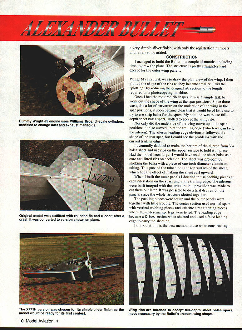
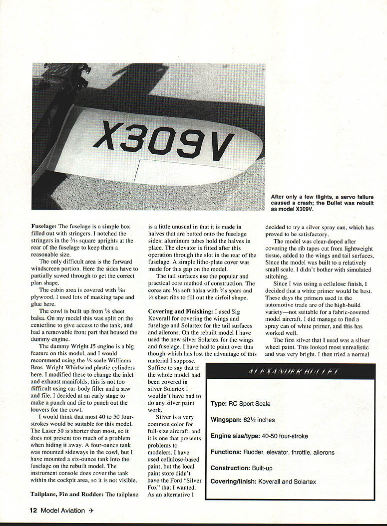
The original model was built quickly to be ready for the Old Warden Scale Weekend, so a very simple finish (silver with registration letters and numbers) was used.
(Editor’s note: the author is the Scale columnist for the British publication Radio Control Models and Electronics.)
Construction
I managed to build the Bullet in a couple of months including time to draw the plans. The structure is straightforward except for the outer wing panels.
Wing
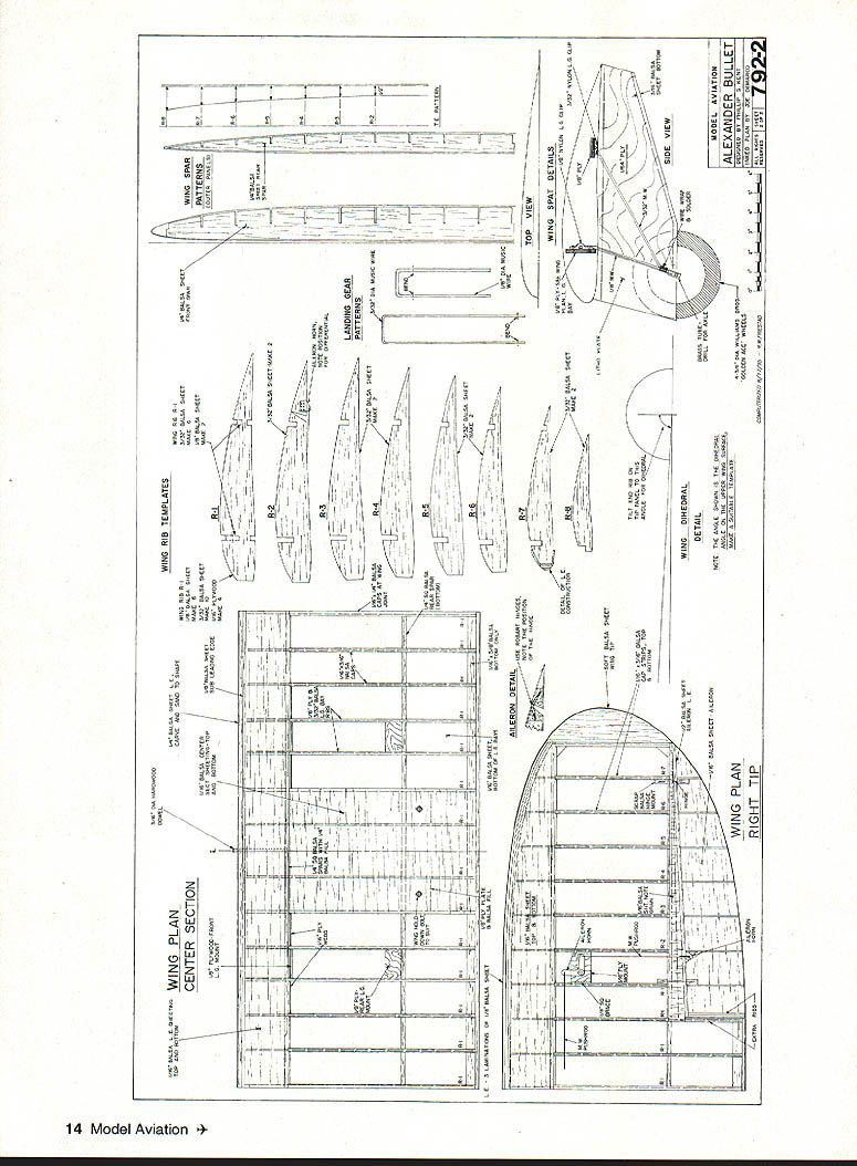
- First task: draw the plan view and plot the wing shape. The ribs reduced in size during plotting; I used a photocopying machine to reduce the original rib-section lengths and obtain the required rib shapes.
- Spar solution: because of considerable curvature on the underside, strip-balsa spars were unsuitable. I used full-depth sheet-balsa spars slotted to accept the ribs. The underside curvature meant the spar positions also curved up toward the trailing edge; the aileron leading edge follows the shape of the rear spar.
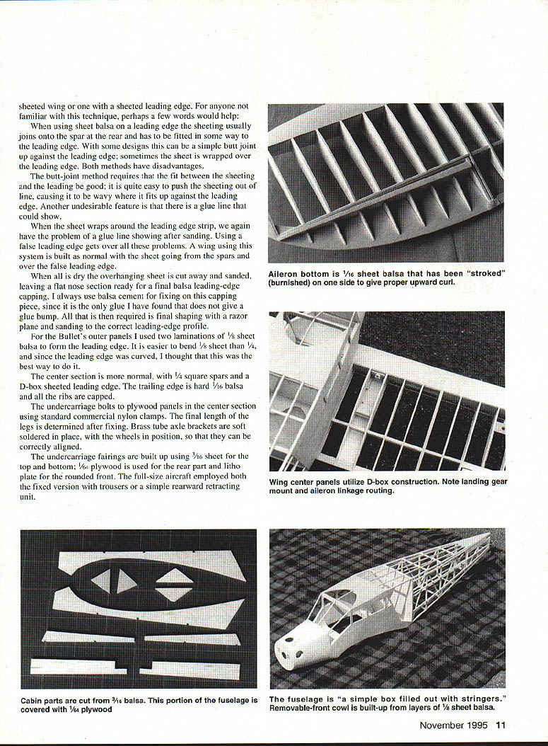
- Ailerons: the curved trailing edge led me to make the bottom surface of the aileron from 1/16" balsa sheet, with ribs on the upper surface to hold it in place. On a larger model I would have used a sheet-balsa core fitted with ribs.
- Pre-bending sheeting: to pre-bend a side sheet, stroke a balsa piece over a 1" diameter aluminium tube and push the tube along the top surface — this makes the sheet curl upward.
- Outer panels: I used packing pieces at the rib stations when setting up spars and the trailing edge. The ailerons were built integral to the panels with provision for cutting them out later. Since the whole structure slotted together, the panels assembled with little trouble.
- Centre section: normal spars with vertical webbing pieces and strengthening where the undercarriage legs fit. The leading edge was formed as a D-box and sheeted; I used a false leading edge to carry the sheeting — this avoids glue-line and fit problems associated with butt joints or wrapping the sheet over the leading edge.
- Leading-edge construction: for the outer panels I used two laminations of 1/8" sheet balsa to form the leading edge (easier to bend than 1/4"). The centre section uses 1/4" square spars, a D-box sheeted leading edge, hard 1/16" balsa trailing edge, and capped ribs.
Notes on sheeting technique:
- Butt-joint against the leading edge requires a very close fit and can produce waves or visible glue lines.
- Wrapping the sheet over the leading edge can leave a visible glue line after sanding.
- A false leading edge lets you sheet from the spars over the false leading edge, then cut away the overhang and fit a final balsa capping piece with balsa cement (avoids glue bumps). Final shaping is done with a razor plane and sanding.
Fuselage
- Structure: simple box with stringers. Stringers were notched into 7/16" square uprights at the rear to keep them a reasonable size.
- Windscreen area: the forward windscreen portion is tricky — the sides must be partially sawed through to get the correct plan shape.
- Cabin: covered with 1/64" plywood; I used lots of masking tape and glue during assembly.
- Cowl: built from 1/8" sheet balsa, split on the centreline for tank access, with a removable front section housing the dummy engine.
- Dummy engine: the Wright J5 is a big feature. I recommend using 1/6-scale Williams Bros. Wright Whirlwind plastic cylinders and modifying inlet/exhaust manifolds with car-body filler, saw and file. I made a punch and die to produce the cowl louvers.
- Engine and tank: most 40–50 size four-strokes should be suitable; the Laser .50 is relatively short and easier to hide. On the original I mounted a 4 oz tank sideways in the cowl; on the rebuilt model I used a 6 oz tank in the fuselage. The instrument console covers the tank so it is not visible.
- Undercarriage: bolts to plywood panels in the centre section using standard commercial nylon clamps. Final leg length is set after fixing. Brass-tube axle brackets are soft-soldered in place with wheels positioned for correct alignment. Undercarriage fairings are built from 3/16" sheet top and bottom, 1/16" plywood rear, and litho plate for the rounded front. Full-size aircraft used either fixed trousers or a simple rearward-retracting unit.
Tailplane, Fin and Rudder
- Tailplane: made in halves that butt onto the fuselage sides and are held by aluminium tubes. The elevator is fitted afterwards through the fuselage rear slot; a litho-plate cover was used over this gap.
- Construction method: tail surfaces used the core method — 1/16" soft balsa cores with 3/16" spars and 1/8" sheet ribs to fill the airfoil shape.
Covering and Finishing
- Covering: Sig Koverall for wings and fuselage; Solatex for tail surfaces and ailerons. On the rebuilt model I used silver Solatex for wings and fuselage, though I ended up painting over it.
- Painting: silver can be tricky — initial silver wheel paint looked unrealistically bright. A normal silver spray was better, but still too bright. Spraying over with matte Aerokote fuel proofer produced an excellent look, though my small hobby airbrush left a patchy finish.
- Priming: used a white spray primer (automotive high-build primers are not suitable for fabric-covered models).
- Doping and detailing: model was clear-doped after covering; rib tapes cut from lightweight tissue were added. Simulated stitching was omitted on this relatively small-scale model.
- Simulated metal framing: lettering was cut from Solartrim sheet; after positioning it was sprayed with matte Aerokote. Dummy engine painted with Humbrol matt enamel and silver spray.
Miscellaneous
- Cowl louvers: I made a punch and die to fashion the louvers for the cowl.
- Balance: the full-size aircraft balanced at 28% of the wing chord; I made the model balance in the same place. The heavy engine helps; battery or tank position can be adjusted. Rudder and elevator servos were mounted at the back of the cabin to help balance.
- Internal fittings: instrument console (card and thin plywood) and balsa seats.
Flying doors
- The wing-bolt access door was made working so the wing bolts could be hidden. On the first flight the door detached and was lost. The rebuilt door uses a Du-Bro latch, which is reliable.
Flying
- Despite small-looking fin and rudder, directional stability proved fine; the model flew straight off the board.
- The model took part in the Kings Cup air race at Liverpool and handled well, gaining joint second place. Takeoffs and landings were easy on grass.
Plans and Drawings
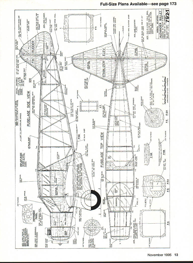
The scanned page included full-size plans and detailed drawing labels only (no running article text). The plans include:
- Fuselage side view
- Fin & rudder
- Stabilizer & elevator
- Fuselage top view
(Various plan detail labels, rib templates and construction notes appear on the drawings.)
Credits and Contact
Phillip Kent 32 Moorbottom Cleckheaton West Yorkshire BD19 6AD England
Transcribed from original scans by AI. Minor OCR errors may remain.

