
Align Your Front End
By T. Michael Jennings
Overview
This simple jig makes achieving a straight, strong front end much easier. The jig takes about two hours to build and costs about eight dollars. It can be adapted to many types of engine-powered model airplanes. With this jig you can build an easy-on, easy-off engine/tank mounting assembly that's lightweight, straight, and strong—resulting in a better-performing, more efficient model that's easier to handle, maintain, and fly.
Planning and design
- Do the paperwork first. The examples here feature an inverted engine installation, but the techniques for upright installations are the same.
- The key variable is the vertical distance between the engine needle-valve centerline and the fuel-tank centerline. If they coincide (as in these examples), similar engine runs for both level and inverted flight should be expected.
- If you prefer to lean out the engine for inverted flight, consider installing the fuel tank 3/8 in. lower.
- Once you find a good engine/fuel-tank combination, stick with it.
Making the drawings
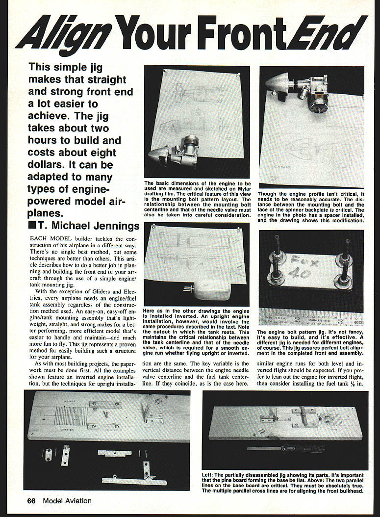
- Use Mylar drafting film for construction drawings. Mylar is stable and durable; a 24 x 36-in. sheet costs about four dollars. You’ll need roughly three square feet—cut sheets as required.
- Make two engine views on Mylar: a side profile with the engine bolted to the spinner assembly, and a bottom view. Use calipers or a 6-in. scale to measure critical engine features.
- Also draw the engine-bearer location and engine mounting bolt holes, showing the engine centerline (C/L).
- For certain designs (Precision Aerobatics, for example) a three-degree offset in the mounting holes may be optimal. Use whatever offset works for your aircraft; the drawings let you lay out hole locations in the maple bearers by placing the Mylar directly over the bearer.
- The next drawing should show the engine profile with a 3/8-in. extension between the engine and spinner assembly. Use an extension on most models (unless a spinner can’t be fitted)—it provides an extra 1/2 in. between the needle valve and the propeller. Note that extensions may cause faster wear on the front engine bearing; bearings can be replaced by hand.
- A final drawing should show the fuel tank, maple engine bearers, mounting plate, and bulkheads. You may put these views on one sheet, but separate sheets give flexibility and allow overlaying to compare front-end geometries and combinations.
Engine bolt-pattern jig
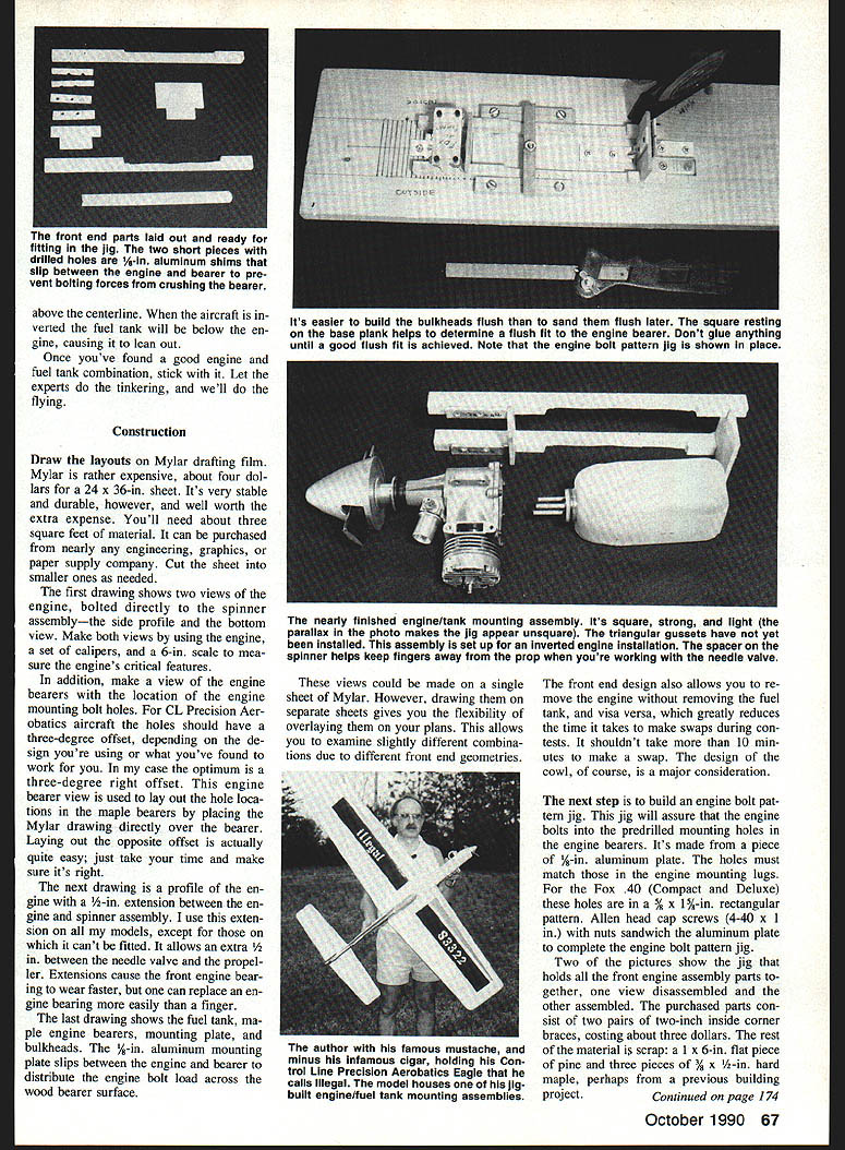
- Build an engine bolt-pattern jig to ensure the engine bolts into the predrilled mounting holes in the engine bearers.
- Make it from 1/8-in. aluminum plate. The holes must match the holes in the engine mounting lugs.
- Example: for the Fox .40 (Compact and Deluxe), the holes are in a 5/8 x 1-1/2-in. rectangular pattern.
- Use Allen-head cap screws (4-40 x 1 in.) with nuts to sandwich the aluminum plate and complete the bolt-pattern jig.
Front-end assembly jig — materials and preparation
Materials (example):
- Two pairs of 2-in. inside corner braces (about three dollars).
- A 1 x 6-in. flat piece of pine (scrap is fine).
- Three pieces of 3/4 x 1/4-in. hard maple (engine bearers).
- Aircraft plywood bulkheads (not Lite Ply).
- 1/8-in. aluminum mounting plate (to distribute engine-bolt load).
Steps:
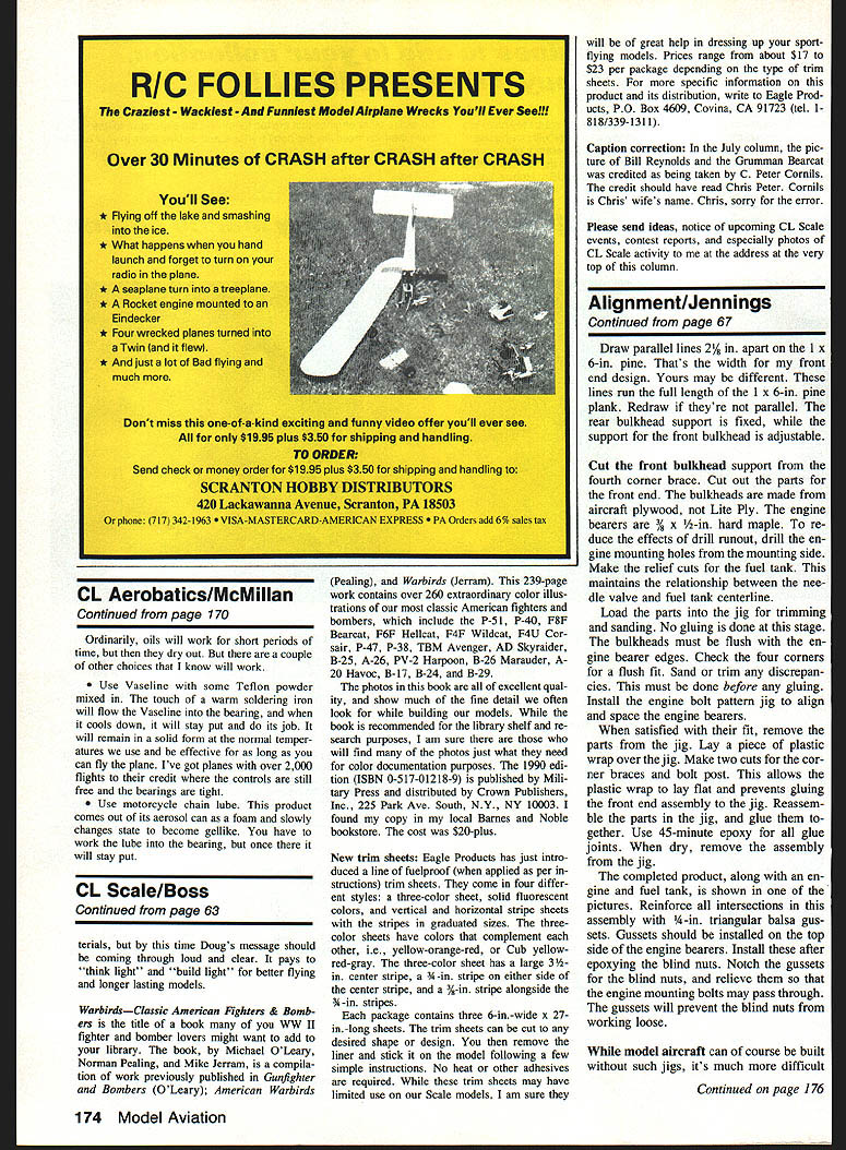
- Draw parallel lines 2 1/4 in. apart along the full length of the 1 x 6-in. pine—this is the width used in this front-end design (yours may differ). Redraw if the lines are not parallel.
- The rear bulkhead support is fixed; the front bulkhead support is adjustable.
- Cut the front bulkhead support from the fourth corner brace. Cut out the parts for the front end.
- Use 3/8 x 1/2-in. hard maple for the engine bearers.
- Drill the engine-mounting holes from the mounting side to reduce drill runout effects.
- Make the relief cuts for the fuel tank to maintain the relationship between the engine and tank centerlines.
Fitting, gluing, and assembly
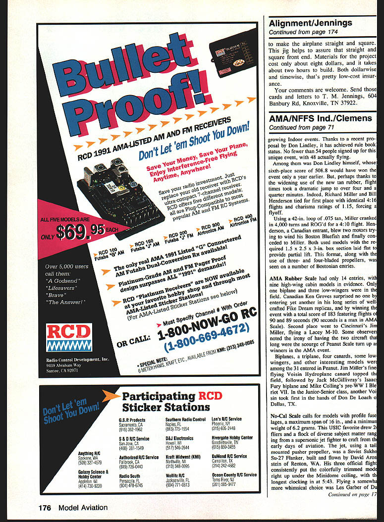
- Load the parts into the jig for trimming and sanding. Do not glue at this stage.
- Ensure the bulkheads are flush with the engine bearer edges and check all four corners for a flush fit. Sand or trim any discrepancies before gluing.
- Install the engine bolt-pattern jig to align and space the engine bearers while checking fit.
- When satisfied, remove the parts from the jig. Lay a piece of plastic wrap or wax paper on the jig.
- Make two cuts for the corner braces and bolt posts—this allows the braces and bolt posts to be bolted through the parts previously glued to the front-end assembly to the jig.
- Reassemble the parts in the jig and glue them together using 45-minute epoxy for all glue joints.
- When the epoxy is dry, remove the assembly from the jig.
- A 1/8-in. aluminum mounting plate slips between the engine bearers to distribute engine-bolt load across the wood-bearer surface.
- Drawing separate Mylar sheets for parts gives flexibility; overlaying plans allows examination of slightly different combinations.
Reinforcement and finishing
- Reinforce all intersections in the assembly with 1/4-in. triangular balsa gussets installed on the top side of the engine bearers.
- Install gussets after epoxying the blind nuts. Notch and relieve the gussets to clear the blind nuts and allow the engine-mounting bolts to pass through.
- These gussets will help prevent the blind nuts from working loose.
Benefits, cost, and time
- While model aircraft can be built without such jigs, it is much more difficult to make the airplane straight and square without one.
- This jig helps assure a straight and square front end.
- Materials for the project cost about eight dollars, and it takes about two hours to build—low-cost insurance for better construction.
Contact
Send comments to: T. M. Jennings 604 Banbury Rd Knoxville, TN 37922
Transcribed from original scans by AI. Minor OCR errors may remain.

