
All about Electrics
The heart of the electric-powered airplane is the motor. This chapter describes what's in the motor and provides some tips for successful operation and a long useful life. You don't have to know all about electric motors to enjoy flying electrics, but you'll be ahead of the crowd if you do. Part 2 — Bob Kopski
Last month I highlighted many features and characteristics of electric power, noting advantages and disadvantages and showing a variety of electric-powered models. The broad range of applicability and the convenience and fun aspects of this relatively new form of model power were emphasized. So much for the convincing. Now, how does the modeler of average skill make it all happen? Let's start by getting to know more about electric motors.
In a sense, knowledge about conventional gas power reciprocating engines often comes more "naturally." Many feel comfortable, if not familiar, with the family car and lawnmower engines. "Carburetor" is a word not unheard of at the dinner table. Not so with "commutator;" that's a bit more unfamiliar. The unknown can be a bit scary.
The purpose of this installment is to help you feel more comfortable with electric motors by describing some basics. Then I'll get into more detail so you can use them with confidence. We'll cover some things you should do and some things that you shouldn't do. There may be a few things that you didn't know that you should. Some things may not seem necessary to get you started, but they will surely help you keep going. I'll try to make it simple and easy to follow with a minimum of "heavy technical" and a good dose of "why" and "how to," plus plenty of tidbits not collected in any other single publication that I know of. I'll try to arrange this in convenient sections so you can skip around as your interest or need dictates and for easy future reference.
1. What's in a motor?
This is one of those sections you can skip over and still start to fly your model. On the other hand, this little bit of information may help you feel a lot more confident about the subject, because you'll be more familiar with what makes 'em hummmmmmmm!
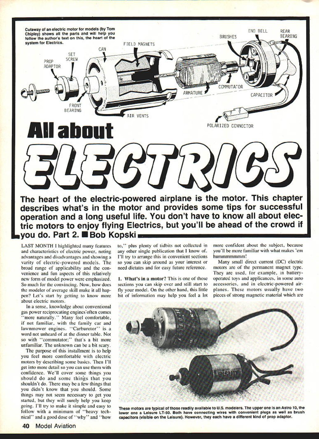
Many small direct-current (DC) electric motors are of the permanent-magnet type. They are used, for example, in battery-operated toys and appliances, in some auto accessories, and in electric-powered airplanes. These motors usually have two pieces of strong magnetic material mounted inside the round iron can housing. The field poles form a strong magnetic field inside the can. The armature assembly rotates within this field.
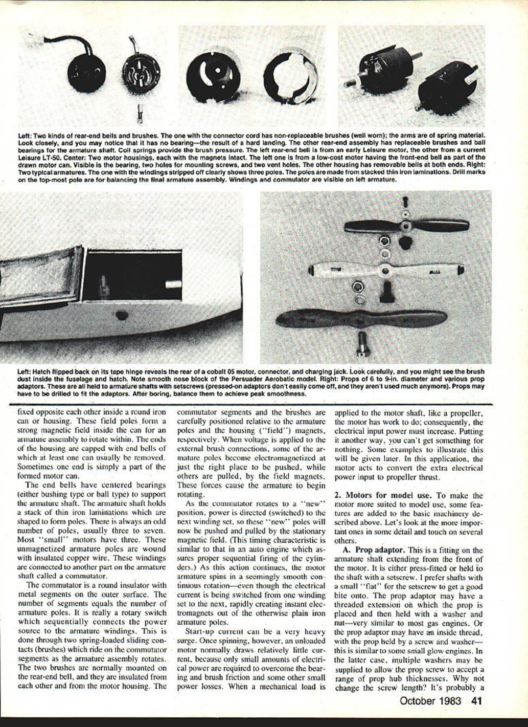
The ends of the housing are capped with end bells, and at least one of these can usually be removed. Sometimes the end is simply part of the formed motor can. End bells have centered bearings, either of the bushing type or the ball type, which support the armature shaft.
The armature shaft holds a stack of thin iron laminations shaped to form the poles. There are always an odd number of poles—usually three or seven. Most small motors have three. The unmagnetized armature poles are wound with insulated copper wire. The windings are connected to another part on the armature shaft called the commutator.
The commutator is a round insulator on which metal segments are mounted. The outer surface of the commutator provides the contact surface for the brushes which transfer current to the rotating armature. Brushes are held against the commutator by springs mounted in the end bell assembly; the brush springs provide the necessary pressure for good electrical contact.
The number of segments equals the number of armature poles. It is really a rotary switch which sequentially connects the power source to the armature windings. This is done through two spring-loaded sliding contacts (brushes) which ride on the commutator segments as the armature assembly rotates. The two brushes are normally mounted on the rear end bell, and they are insulated from each other and from the motor housing. The commutator segments and the brushes are carefully positioned relative to the armature poles and the housing ("field") magnets, respectively.
When voltage is applied to the external brush connections, some of the armature poles become electromagnetized at just the right place to be pushed, while others are pulled, by the field magnets. These forces cause the armature to begin rotating. As the commutator rotates to a new position, power is directed (switched) to the next winding set, so these new poles will now be pushed and pulled by the stationary magnetic field. This timing characteristic is similar to that in an auto engine which assures proper sequential firing of the cylinders.
Start-up current can be a very heavy surge. Once spinning, however, an unloaded motor normally draws relatively little current, because only small amounts of electrical power are required to overcome the bearing and brush friction and some other small power losses. When a mechanical load is applied to the motor shaft, like a propeller, the motor has work to do; consequently, the electrical input power must increase. In this application, the motor converts the extra electrical power input to propeller thrust.
2. Motors for model use
To make the motor more suited to model use, some features are added to the basic machinery described above. Let's look at the more important ones in some detail and touch on several others.
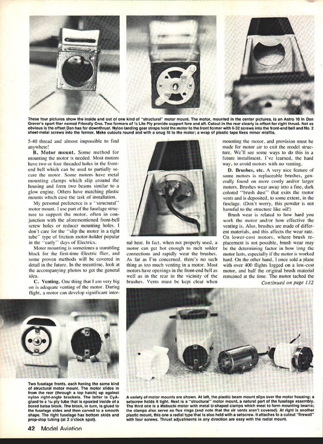
A. Prop adaptor
This is a fitting on the armature shaft extending from the front of the motor. It is either press-fitted or held to the shaft with a setscrew. I prefer shafts with a small flat for the setscrew to get a good bite on. The prop adaptor may have a threaded extension on which the prop is placed and then held with a washer and nut—very similar to most gas models. Or the prop adaptor may have an inside thread, with the prop held by a screw and washer—this is similar to some small glow engines. In the latter case, multiple washers may be supplied to allow the prop screw to accept a range of prop hub thicknesses. After boring props to fit the adaptor, balance them to achieve peak smoothness.
Note: some adaptors are predrilled to accept a pin; others are press-fitted and not intended to be removed. Small threads such as 5-40 are common on some adaptors and can be hard to find replacements for.
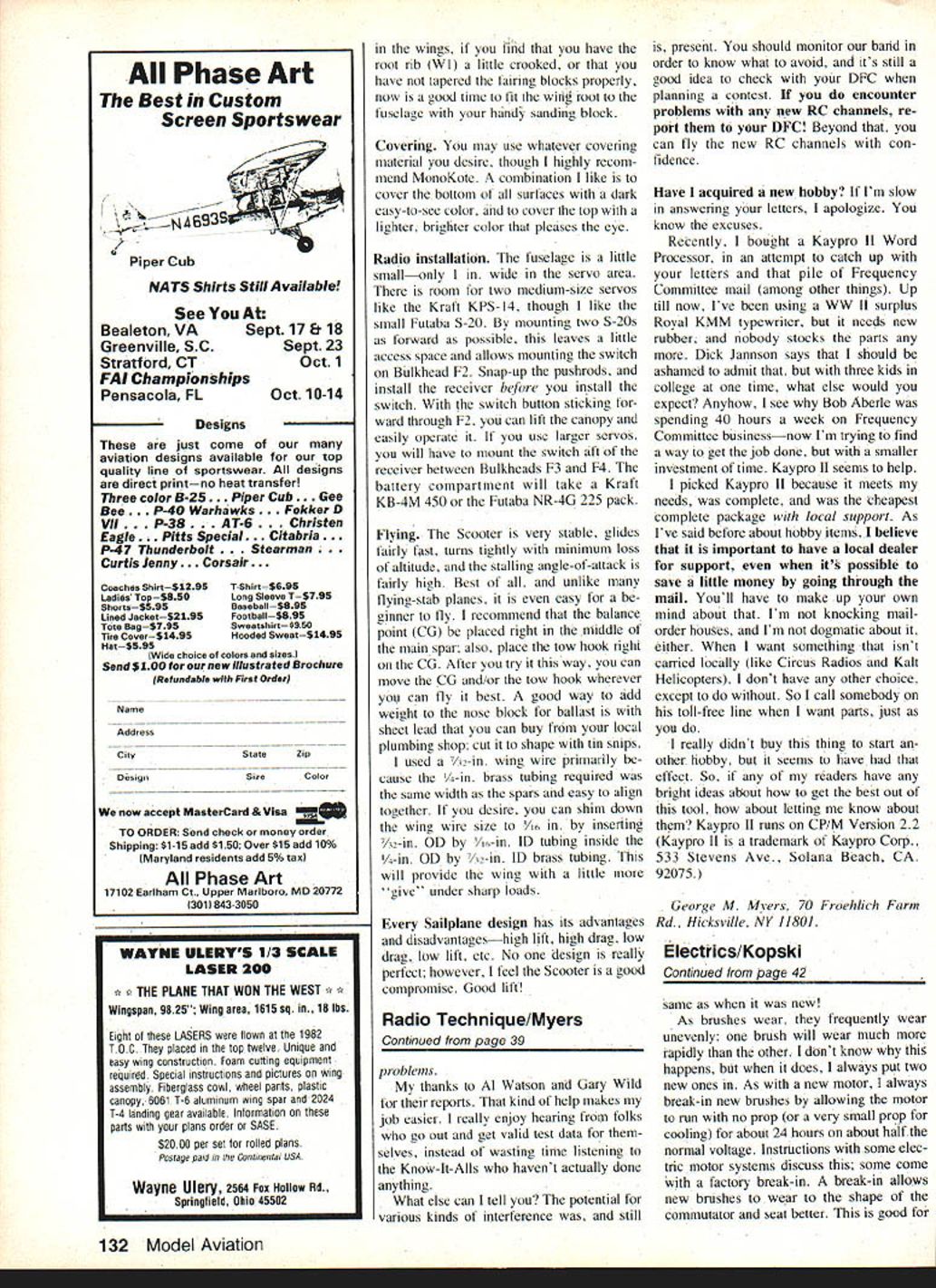
B. Motor mount
Some method for mounting the motor is needed. Most motors have two or four threaded holes in the front end bell which can be used to partially secure the motor. Some motors have metal mounting clamps which slip around the housing and form two beams similar to a glow engine. Others have matching plastic mounts which ease the task of installation.
My personal preference is a "structural" motor mount. I use part of the fuselage structure to support the motor, often in conjunction with the aforementioned front-bell screw holes or reducer mounting holes. I don't care for the "slip the motor in a tight tube" type of friction motor holder popular in the early days of electrics.
Motor mounting is sometimes a stumbling block for the first-time electric flier, and some proven methods will be covered in detail in the future. In the meantime, examine photos and installations to get the general idea.
C. Venting
I am very big on adequate venting of the motor. During flight a motor can develop significant internal heat. In fact, when not properly used, a motor can get hot enough to melt solder connections and rapidly wear the brushes. As far as I'm concerned, there's no such thing as too much venting in a motor. Most motors have openings in the front end bell as well as in the rear in the vicinity of the brushes. Vents must be kept clear when mounting the motor, and provision must be made for motor air to exit the model structure. I've learned the hard way to avoid motors with no venting.
D. Brushes and the commutator
A very nice feature of some motors is replaceable brushes, generally found on more costly and/or larger motors. Brushes wear away into a fine, dark-colored "brush dust" that exits the motor vents and is deposited, to some extent, in the fuselage. This powder is not harmful to the structure like oil.
Brush wear is related to how hard you work the motor and how effective the venting is. Brushes are made of different materials, and this affects the wear rate. On lower-cost motors, where brush replacement is not possible, brush wear may be the determining factor in how long the motor lasts, especially if the motor is worked hard. On the other hand, I've seen low-cost motors that lasted for hundreds of flights with plenty of brush material remaining.
As brushes wear, they frequently wear unevenly; one brush will wear much more rapidly than the other. When this happens I always install two new brushes. As with a new motor, break in new brushes by allowing the motor to run with no prop on (or a very small prop for cooling) for about 24 hours on roughly half the normal voltage. A break-in allows new brushes to wear to the shape of the commutator and seat better; this is good for motor life. Some systems come with factory break-in instructions.
When installing replacement brushes, make sure the springs are not distorted and that the brushes move freely in their holders; bent springs or binding brushes cause sparking and poor contact. If brushes become "banked" and cut a groove in the commutator, the commutator must be trued or replaced.
Commutators are made of a much harder material than brushes, so they normally do not wear away. However, if the brushes are allowed to wear down completely so that the metal brush arm or brush springs begin to ride on the commutator, it will probably become scored, motor performance will decline, and electrical noise due to excessive sparking is likely. The commutator could be permanently ruined. To avoid this problem, inspect the brushes occasionally, especially those that are replaceable. Some are visible through the vent holes so disassembly is not necessary for inspection. Others are easily removed externally from the brush holders by unscrewing the caps. Handle brushes carefully and replace them the same way they came out.
I've seen other problems in the brush-commutator area. Some motors may display a noticeable performance drop and erratic running for no apparent reason. This is often associated with excessive brush sparking and possibly radio glitches. It may be due to inadequate brush pressure, even though the brushes show little wear. If the brush arms, which are spring material on lower-cost motors, become overheated due to the motor being overworked, they may lose some tension.
Another effect of high heat can be commutator distortion. If the commutator gets out of round, brush bounce occurs. In this case, even brushes in excellent condition can't do the job. This can be seen during break-in where the unloaded (unpropped) motor runs erratically. You can actually feel the rotational irregularity in your hand when the commutator is out of round. If you lay the running motor on a table, you can watch it twitch. Use your warranty if your motor is defective as received.
Both inadequate brush pressure and an out-of-round commutator can sometimes be tested by applying a little pressure to either brush through a vent hole with a toothpick. If the motor speed picks up and smooths out noticeably, chances are one of these problems exists.
Sometimes brushes become a little snug in their guides and the pressure is effectively reduced. Brush dust can clog the guide a bit. Removing the brushes, wiping them with a tissue, and cleaning the guide tube with a dry pipe cleaner often fixes the problem. Handle the brushes carefully and avoid contaminating them with your fingers.
If the motor has been run hard, some brush material may be smeared heavily on the commutator surface and prevent good electrical contact. A possible cure: take the prop off and run the motor with the normal battery pack for two or three minutes, then replace the prop. You may see a noticeable improvement.
If possible, note motor/battery performance when new (after break-in). Record RPM with a particular prop (size and make) and battery voltage at that time. Later, if there's a question about performance, these data can be compared. This is similar to range-checking a radio and rechecking under the same conditions at a later date.
A crash or even a hard bump on the prop or prop adaptor can easily bend the armature shaft, resulting in obvious wobble and vibration. Sometimes the shaft can be straightened so that the prop will run true, but the armature may still wobble due to a shaft bend behind the front bearing. This also causes brush bounce and erratic running. Some higher-quality motors have armature replacements that can be bought; in many cases this is the only recourse unless you're into machine work. Sometimes the impact can be severe enough for the rear end bell and/or bearing to break or get pushed out by the rearward-driven armature assembly. Be careful, and use a flexible nylon prop and/or a prop stop (to stop the prop in a horizontal position) to minimize such problems.
E. Bearings
Electric motors for models have either sleeve (bushing) bearings or ball bearings. Usually, the sleeve bearings are self-lubricating and self-centering. The motor with over 400 flights I mentioned was of this type; it eventually was replaced after bearing wear caused unacceptable noise.
Ball bearings are found on larger and/or more costly motors. A somewhat unpleasant contradiction is a more costly motor with ball bearings and non-replaceable brushes—this is a little like a car with non-replaceable tires.
Given the choice, I'm content with sleeve bearings on small motors. I'm not convinced that ball bearings are worth the added cost for the kind of flying I do. They may afford a competitive edge, but this series and most of my flying are addressed to fun and sport flying.
Whatever the bearing type, never add lubricant to the motor bearings.
F. Other motor features
Some other attributes that make a motor better for model aircraft often include:
- A wire set with a suitable polarized connector or terminals for easy connections.
- One or more capacitors wired to the brush terminals to help suppress electrical noise which may otherwise interfere with RC operation.
- High-temperature insulation and epoxy coating of the windings.
- Lacing of the wires at the commutator connections to keep everything in place.
- Finely finished and balanced armatures to assure smooth, vibration-free operation.
- Neutral timing so that the motor turns equally well in either direction, or offset timing to maximize performance in the normal direction for propeller use.
Some motors pack higher power handling capability in a small case through the use of very high-strength field magnets, such as samarium-cobalt material. This feature adds to the motor price, but the armature shafts still bend easily—so pay attention on landing.
The German Keller motor is available with flux rings. These are metal bands slipped over the outside of the motor can to make the case thicker. Without them, a thin case motor works best with small props at high revs. Adding one or more flux rings increases torque, allowing the motor to turn larger props more efficiently at lower RPM. It's like having a variety of motors in one.
3. Motor size
Motor size is often a subject of confusion for beginners. It's presently a cause for much discussion in the modeling industry. Opinions vary as to how to specify sizes or classes. Eventually some standards will emerge, as the AMA, SEAM (Society of Electric Aircraft Modelers), and other interested parties sort out the best options.
This is not necessarily a simple task. Unlike a gas engine, typically characterized by displacement (in cubic inches), there are several candidate ways to characterize electric motors. One way would be to measure physical size, such as armature dimensions or overall motor weight. Another way is to describe the battery instead of the motor, where size or class is determined by the number and/or kind of cells in the motor battery. This method is used in Europe for FAI events. It will be interesting to see how this is settled.
Historically, many motors in the U.S. have descriptions that sound like gas engine sizes. For example, the most popular motor size is an "05." This has come to mean that the motor would swing the same size prop at about the same RPM as the typical glow .049 counterpart. Thus, an 05 example would probably use a 6-in. diameter, 4-in. pitch prop and turn that prop at about the same speed as many glow .049s. Similarly, an electric 15 might swing an 8-4 prop.
While this sounds simple enough, it isn't. Things are changing. Electric is evolving, and there are some growing pains. My cobalt 05, for example, can easily out-power a .049 glow engine—and swing a much heftier prop too. It's really not a "good ol' 05." Windings and designs change, and identical nomenclature or catalog numbers do not guarantee identical performance over time. This illustrates the increasing need for size or class standards, and it reminds us of the present dynamics in this relatively new area of model aviation. So be advised, but don't be discouraged.
Consider the small number of U.S. suppliers who have stuck with electric-powered flight products. It's been a long, lean decade of dedication, perseverance, and belief in the future. Without them, you wouldn't be reading this.
4. When do we get to the good stuff?
We're nearing the end of Part Two of this series, and I know many readers may be anxious to get on with building and flying something. That's understandable. But let's pause and put this whole electric thing in perspective. It's relatively new and unfamiliar to most modelers, including some who are very astute and skilled. Based on inquiries I receive, this subject continues to bring far more questions than there are readily available answers.
Consider the many basic articles devoted to conventional engines in popular magazines; people still have questions. Look at the relative scarcity of basic articles devoted to electric motors, electric flight batteries, or electric anything else—all those unanswered questions. Not many have been published.
We all know someone in the flying group who's "got it all together." He's the guy with experience, whose engines always run right, who maintains his equipment, who is a specialist in some area. This guy knows an awful lot about modeling in general, too. This series aims to give readers that same confidence in electrics: basics plus examples.
While this series will have plenty of "how to" examples as we go along, its parallel goal is to convey a basic understanding of the fundamental aspects of electric-powered flight. With that under your hat, you'll soon be able to answer such questions as what motor is needed to fly what plane and what it should weigh to assure so much flight time.
Soon the electric products of today will become dated, as will specific "how to" examples based on them. I don't want this series to become dated; I want it to continue to be of basic value in the understanding and utilization of whatever new and better products come along. Those who have a reasonable acquaintance with how and why electric works will have no trouble obtaining first-time and continuing success.
For the very anxious, while you're following this series, keep your eye on contemporary magazines as a good source of suitable electric designs. Many have already been published. MA alone has had three or four in the last year. These articles typically include the electric system information for the design. Later this series will suggest guidelines for motor/plane combinations that will assure success. Installation "how to" is coming. As mentioned in Part One, a very versatile RC design, the Spectra, which can accommodate a variety of electric power systems, is planned as a construction article.
Next up, Part Three will discuss propellers and electric power. The motor's sole function is to convert energy stored in the battery to propeller thrust. I'm sure many of you will be amazed at just what it takes to turn a prop, how various props compare, and how a prop change affects flight performance. I think you'll find Part Three enlightening, though still fundamental, and also graphic and unique. I don't think anything like it has been published before.
Part Four will be devoted to batteries—everything about batteries. Installations and plane suggestions will follow.
Now for the answer to the title question: this is the good stuff, and it will continue, and it will eventually all come together. I promise.
As I continue with the challenge of this series, I've come to appreciate its sizeable scope. It is very difficult to write a compact, complete, and simple introduction to electrics. In this regard, I want to thank my wife, Wilma; MA Editor Carl Wheeley; Columnist Bill Winter; and my electric flying friends from KRC — Herb Dirks, John Hickey, Heinz Koerner, Don LeGower, and Dan Mitten — for critiquing my drafts and artworks and for their many helpful suggestions.
Any questions related to this part or earlier parts of the series may be directed (with SASE) to the author, Bob Kopski, 25 West End Dr., Lansdale, PA 19446.
Transcribed from original scans by AI. Minor OCR errors may remain.

