
All about Electrics
Part 5 — Bob Kopski
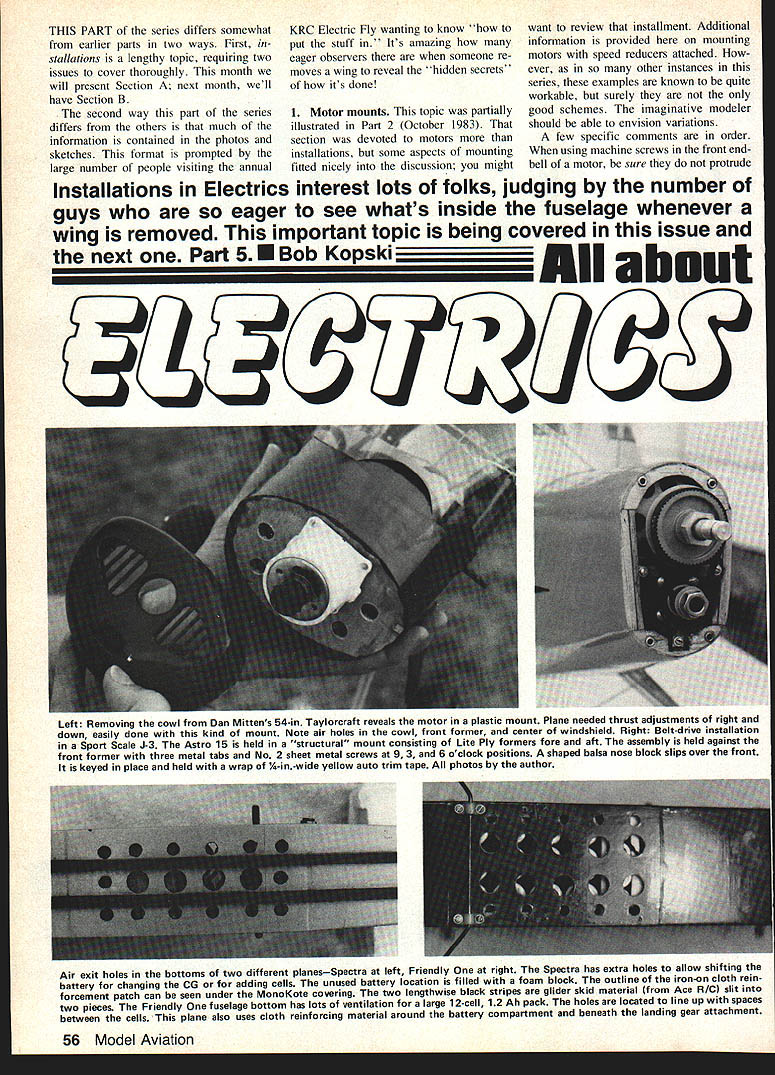
Installations in electrics interest lots of folks, judging by the number of people eager to see what's inside the fuselage whenever a wing is removed. This important topic is being covered in this issue and the next one. This part differs from earlier installments in two ways. First, installations is a lengthy topic requiring two issues to cover thoroughly: this month we present Section A; next month we'll have Section B. Second, much of the useful information is contained in the photos and sketches — prompted by the many people at events who want to know "how to put the stuff in."
1. Motor mounts
A good motor mount will support the motor front and rear and take the torsional and thrust loads produced. If you fabricate a mount with light plywood formers and metal or nylon angle fittings, use screws into tapped holes or captive nuts. If you use a soft-balsa nose block, line the balsa hole with 1/64" plywood or otherwise reinforce the screw holes to prevent crushing.
Specific points:
- When using machine screws in the front endbell of a motor, be sure they do not protrude into the armature.
- Prevent motor rotation: use front endbell mounting holes, clamps, plastic motor mounts, setscrews, or captive fittings.
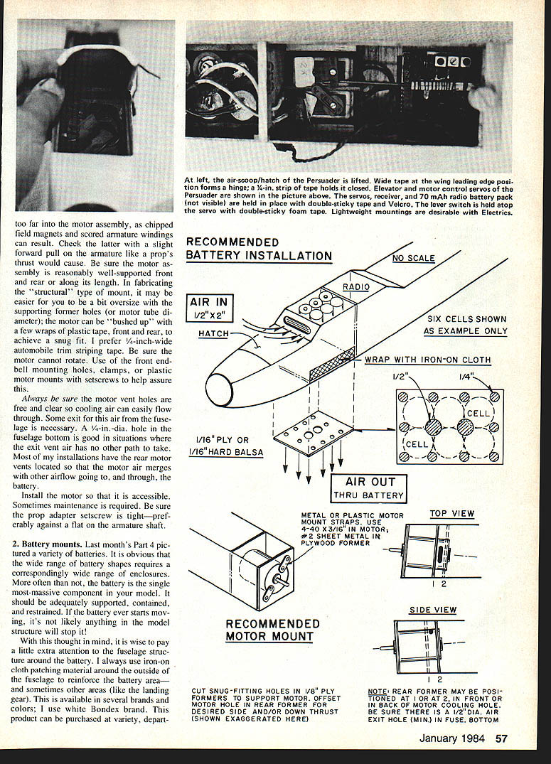
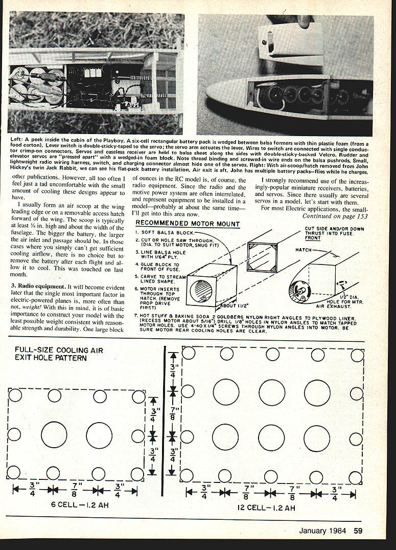
- Be sure motor vent holes are clear so cooling air can flow through. Some installations require an exit vent in the fuselage; a 1/4-in.-dia. hole in the fuselage bottom is effective where that exit air has no other path.
- Most installations locate the rear motor vents so motor air merges with other airflow through the battery compartment.
- Install the motor so it is accessible — maintenance is sometimes required.
- Be sure the prop-adapter setscrew is tight, preferably against the flat on the armature shaft.
- When fabricating a structural-type mount, it may be easier to make the former slightly oversize and "bush up" the motor tube with a few wraps of plastic tape front and rear for a snug fit. I prefer 1/4-in.-wide automobile trim (striping) tape.
Make sure any skin or cowling around the motor has adequate openings for air entry and exit. If using soft balsa for the nose block, reinforce around screw holes to prevent crushing. Use screws into reinforced areas or line with thin plywood where appropriate.
2. Battery mounts
Batteries come in many shapes, and the wide range of shapes requires a correspondingly wide range of enclosures. Often the battery is the single most massive component in the model; it must be adequately supported, contained, and restrained. If a battery starts moving in flight, the structural damage can be severe.
Installation tips:
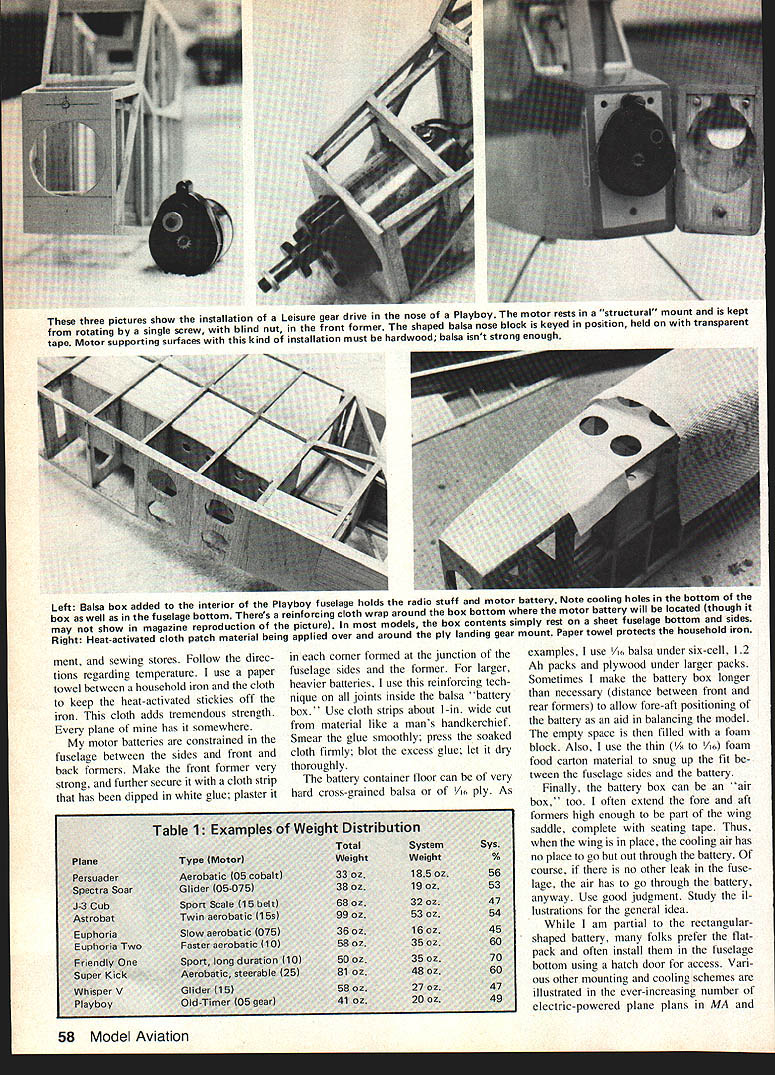
- Reinforce the fuselage around the battery. I always use iron-on cloth patching material around the outside of the fuselage to reinforce the battery area and other high-stress areas (such as landing gear attachments). Several brands and colors are available; I use white Bondex. Follow the iron-on directions regarding temperature and use a paper towel between a household iron and the cloth to keep sticky residue off the iron.
- Make the front former very strong. Further secure it with a cloth strip dipped in white glue and plastered into each corner where the fuselage sides meet the former. For larger batteries, use this reinforcing technique on all joints inside the balsa "battery box."
- Use cloth strips about 1 in. wide (cut from the iron-on material), smear the glue smoothly, press the soaked cloth firmly, blot excess glue, and let dry thoroughly.
- Battery container floor can be hard cross-grained balsa or 1/8-ply. For example, use 1/8 balsa under six-cell 1.2 Ah packs and plywood under larger packs.
- Sometimes make the battery box longer than necessary to allow fore-aft positioning for balancing; fill empty space with a foam block. Use thin foam (1/8 to 1/16 in.) to snug the battery fit between fuselage sides.
- Install batteries so they are secure but accessible. Use straps, clips, or a removable tray to prevent fore-aft or rotational movement.
- Keep up with pack condition. Swollen or damaged cells are hazardous and should be replaced.
- Consider the battery box as part of the cooling airflow. Extend fore and aft formers high enough to be part of the wing saddle; with the wing in place, cooling air has to pass through the battery compartment. Use good judgment and study illustrations for the general idea.
Cooling and airflow:
- I usually form an air scoop at the wing leading edge or on a removable access hatch forward of the wing. A typical scoop is at least 3/8 in. high and about the width of the fuselage. The larger the battery, the larger the air inlet and passage should be.
- If sufficient cooling airflow cannot be achieved, you may need to remove the battery after each flight and allow it to cool.
Table 1: Examples of Weight Distribution
- Persuader — Aerobatic (0.05 cobalt) — Total: 33 oz. — System: 18.5 oz. — Sys. %: 56
- Spectra Soar — Glider (0.05–0.075) — Total: 38 oz. — System: 19 oz. — Sys. %: 53
- J-3 Cub — Sport Scale (0.15 belt) — Total: 68 oz. — System: 32 oz. — Sys. %: 47
- Astrobat — Twin aerobatic (15s) — Total: 99 oz. — System: 53 oz. — Sys. %: 54
- Euphoria — Slow aerobatic (0.075) — Total: 36 oz. — System: 16 oz. — Sys. %: 45
- Euphoria Two — Faster aerobatic (0.10) — Total: 58 oz. — System: 35 oz. — Sys. %: 60
- Friendly One — Sport, long duration (0.10) — Total: 50 oz. — System: 35 oz. — Sys. %: 70
- Super Kick — Aerobatic, steerable (0.25) — Total: 81 oz. — System: 48 oz. — Sys. %: 60
- Whisper V — Glider (0.15) — Total: 58 oz. — System: 27 oz. — Sys. %: 47
- Playboy — Old-Timer (0.05 geared) — Total: 41 oz. — System: 20 oz. — Sys. %: 49
While I am partial to rectangular-shaped batteries, many prefer flat packs and install them in the fuselage bottom using a hatch door for access. Various other mounting and cooling schemes appear in electric-plane plans; often I feel some of those designs provide minimal cooling, so consider adding scoops or vents.
3. Radio equipment
Weight is often the single most important factor in electric-powered planes, so construct with the least possible weight consistent with strength and durability. Radio equipment is one of the larger blocks of ounces in an RC model, so choose light components when practical.
Recommendations and observations:
- I strongly recommend the increasingly popular miniature receivers, batteries, and servos. Since several servos are usually installed, start with servos: for most electric applications the small servos are quite satisfactory, though large or fast planes with heavy control loads may require larger units.
- My current installations use Bantam Midget mechanics; others include D&R Micro mechanics, Futaba S-20s, World S22s, Cannon Micro, and similar. The listed servos/mechanics are typically under one ounce and work well for most electric applications.
- I use 250 mAh flight packs or smaller. The 250s go into glider types (long flight times), large ships, and aerobatic planes (which have heavier servo loads). Smaller packs are practical if you keep track of flying time.
- Example: My aerobatic Persuader uses 70 mAh cells taken from G.E. nine-volt Ni-Cd assemblies. On the bench, continuously moving the ailerons and elevator, the pack ran down in 22 minutes. Typical Persuader flights are 4–5 minutes; I fly the plane four times, then run the pack down fully and fast-charge at the field.
Charging and servicing:
- Arrange equipment so charging and replacement of cells is convenient in the field.
- Monitor packs and replace cells or packs that show deterioration.
RECOMMENDED MOTOR MOUNT
- Soft balsa block.
- Cut or hole-saw through to suit the motor for a snug fit.
- Line the balsa hole with 1/64" ply.
- Glue block to front of fuselage.
- Carve to a streamlined shape.
- Motor inserts through top hatch (remove prop for this).
- Use hot-stuff epoxy and baking soda to set if desired. Recess motor about 5/16". Use Goldberg nylon right-angle brackets to plywood liner; drill 1/8" holes in nylon angles to match tapped motor holes. Use 4-40 x 1/4" screws through nylon angles into motor. Be sure motor rear cooling holes are clear.
Follow these mounting suggestions and make sure the installation allows access for maintenance and cooling airflow.
Wrap-up and contact
- This issue is part one of a two-part installation series; next month will include Section B and a wrap-up addressing frequently asked questions and incidentals.
- The Spectra construction article is still planned for the conclusion of the series.
Please forward any questions (with SASE) to: Bob Kopski 25 West End Dr. Lansdale, PA 19446
I apologize for any past delays in responses and remain intent on answering expediently, conditions permitting.
Transcribed from original scans by AI. Minor OCR errors may remain.

