
All about Electrics
Part 6. Bob Kopski
Half of the installations topic was covered last month—motor, battery, and radio (the big items). This month the author looks at the installation of switches, connectors, fuses, wiring, etc.—the smaller things that are equally necessary. You may want to review Part 5 as you go through this one. They are related, and some pictures and sketches cover mutual areas.
1. Switches
Generally, two common types are used in electric power systems: miniature toggle and miniature snap-action switches (microswitches). Switches are used in a variety of ways—manually or servo-driven—to do different things, such as a simple ON-OFF operation, or to change speed in steps, as in OFF-LO-HI.
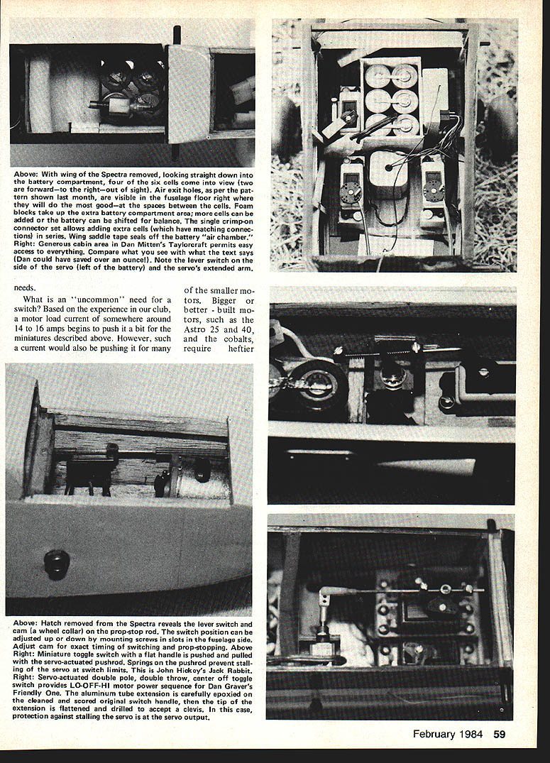
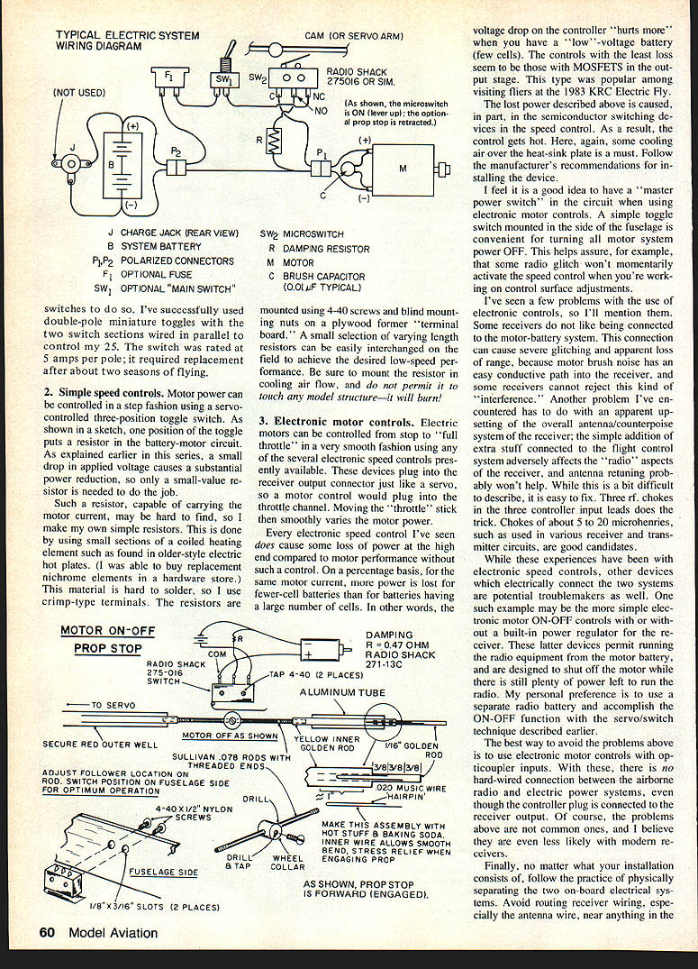
A toggle switch is easily mounted on the fuselage for an external "master power control." Or a toggle may be mounted internally and actuated through a simple servo and pushrod arrangement. A three-position toggle (ON-OFF-ON) allows the OFF-LO-HI function.
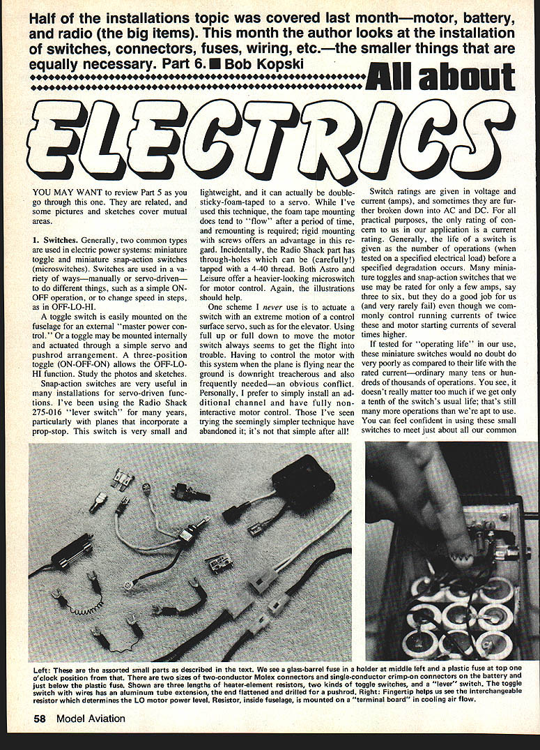
Snap-action switches are very useful in many installations for servo-driven functions. I've been using the Radio Shack 275-016 "lever switch" for many years, particularly with planes that incorporate a prop-stop. This switch is very small and lightweight, and it can actually be double-sticky-foam-taped to a servo. While I've used this technique, the foam tape mounting does tend to "flow" after a period of time, and remounting is required; rigid mounting with screws offers an advantage in this regard. Incidentally, the Radio Shack part has through-holes which can be (carefully) tapped with a 4-40 thread. Both Astro and Leisure offer a heavier-looking microswitch for motor control.
One scheme I never use is to actuate a switch with an extreme motion of a control surface servo, such as for the elevator. Using full up or full down to move the motor switch always seems to get the flight into trouble. Having to control the motor with this system when the plane is flying near the ground is downright treacherous and also frequently needed—an obvious conflict. Personally, I prefer to simply install an additional channel and have fully noninteractive motor control. Those I've seen trying the seemingly simpler technique have abandoned it; it's not that simple after all.
Switch ratings are given in voltage and current (amps), and sometimes they are further broken down into AC and DC. For all practical purposes, the only rating of concern to us in our application is current. Generally, the life of a switch is given as the number of operations (when tested on a specified electrical load) before a specified degradation occurs. Many miniature toggles and snap-action switches that we use may be rated for only a few amps, say three to six, but they do a good job for us (and very rarely fail) even with commonly encountered control running currents of twice the rated current—and motor starting currents several times higher.
If listed for "operating life" in our use, these miniature switches would no doubt do very poorly as compared to their life with the rated current—ordinarily many tens or hundreds of thousands of operations. It doesn't really matter too much if we get only a tenth of the switch's usual life; that's still many more operations than we're apt to use. You can feel confident in using these small switches to meet just about all our common needs.
What is an "uncommon" need for a switch? Based on the experience in our club, a motor load current of somewhere around 14 to 16 amps begins to push it a bit for the miniatures described above. However, such a current would also be pushing it for many of the smaller motors. Bigger or better-built motors, such as the Astro 25 and 40, and the Cobalts, require heftier switches. I've successfully used double-pole miniature toggles with the two switch sections wired in parallel to control my 25. The switch was rated at 5 amps per pole; it required replacement after about two seasons of flying.
2. Simple speed controls
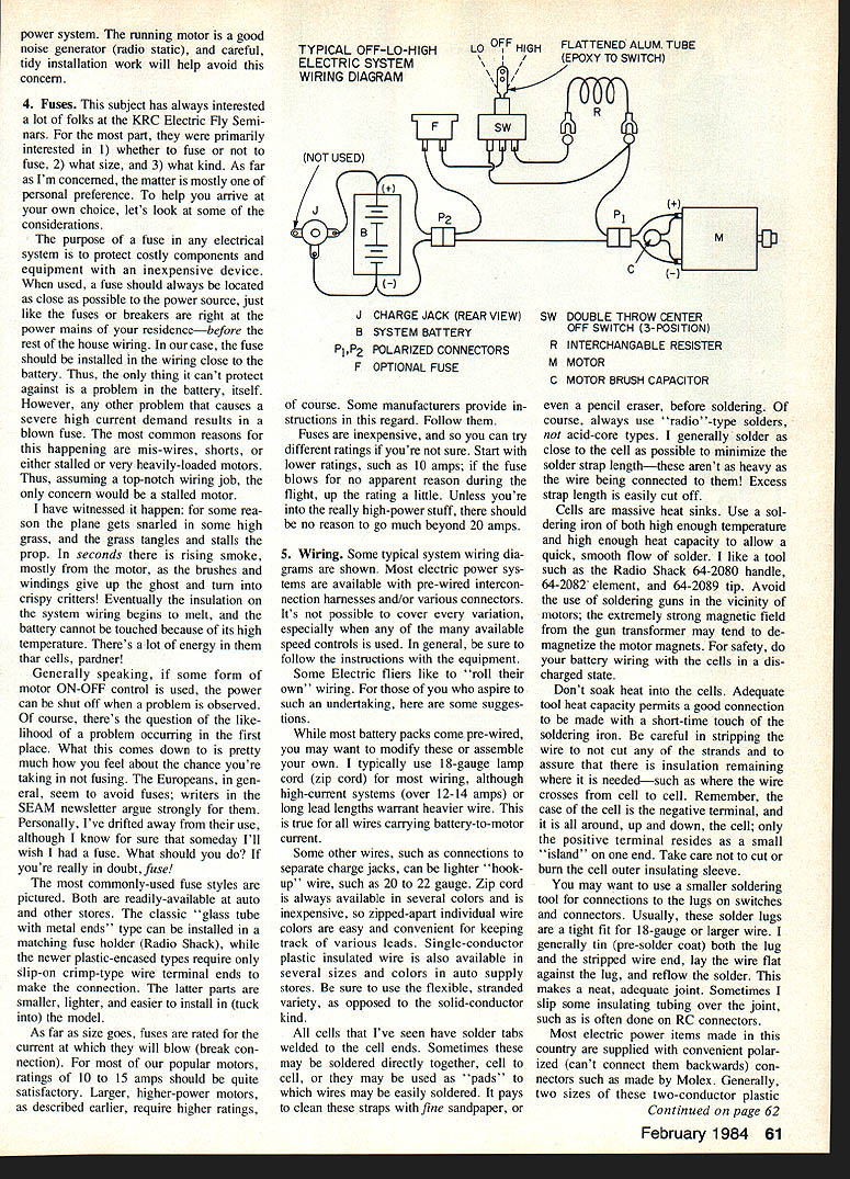
Motor power can be controlled in the same fashion using a servo-controlled three-position toggle switch. One position of the toggle puts a resistor in the battery-motor circuit. As explained earlier in this series, a small drop in applied voltage causes a substantial power reduction, so only a small-value resistor is needed to do the job.
Such a resistor, capable of carrying the motor current, may be hard to find, so I make my own simple resistors. This is done by using small sections of a coiled heating element such as found in older-style electric hot plates. (I was able to buy replacement nichrome elements in a hardware store.) This material is hard to solder, so I use crimp-type terminals. The resistors are mounted using 4-40 screws and blind mounting nuts on a plywood former "terminal board." A small selection of varying length resistors can be easily interchanged on the field to achieve the desired low-speed performance. Be sure to mount the resistor in cooling airflow, and do not permit it to touch any model structure—it will burn!
3. Electronic motor controls
Electric motors can be controlled from stop to "full throttle" in a very smooth fashion using any of the several electronic speed controls presently available. These devices plug into the receiver output connector just like a servo, so a motor control would plug into the throttle channel. Moving the "throttle" stick then smoothly varies the motor power.
Every electronic speed control I've seen does cause some loss of power at the high end compared to motor performance without such a control. On a percentage basis, for the same motor current, more power is lost with batteries that have fewer cells than with batteries having a large number of cells. In other words, the voltage drop on the controller "hurts more" when you have a low-voltage battery (few cells). The controls with the least loss seem to be those with MOSFETs in the output stage. This type was popular among visiting fliers at the 1983 KRC Electric Fly.
The lost power described above is caused, in part, by the semiconductor switching devices in the speed control. As a result, the control gets hot. Some cooling air over the heat-sink plate is a must. Follow the manufacturer's recommendations for installing the device.
I feel it is a good idea to have a "master power switch" in the circuit when using electronic motor controls. A simple toggle switch mounted in the side of the fuselage is convenient for turning all motor system power OFF. This helps assure, for example, that some radio glitch won't momentarily activate the speed control when you're working on control surface adjustments.
I've seen a few problems with the use of electronic controls, so I'll mention them. Some receivers do not like being connected to the motor-battery system. This connection can cause severe glitching and apparent loss of range, because motor brush noise has an easy conductive path into the receiver, and some receivers cannot reject this kind of interference. Another problem I've encountered has to do with an apparent upsetting of the overall antenna/counterpoise system of the receiver; the simple addition of extra stuff connected to the flight control system can adversely affect the radio aspects of the receiver, and antenna rerouting probably won't help. While this is a bit difficult to describe, it is easy to fix. Three RF chokes in the three controller input leads does the trick. Chokes of about 5 to 20 microhenries, such as used in various receiver and transmitter circuits, are good candidates.
While these experiences have been with electronic speed controls, other devices that electrically connect the two systems are potential troublemakers as well. One such example may be the more simple electronic motor ON-OFF controls with or without a built-in power regulator for the receiver. These latter devices permit running the radio equipment from the motor battery, and are designed to shunt off the motor while there is still plenty of power left to run the radio. My personal preference is to use a separate radio battery and accomplish the ON-OFF feature with the servo/switch technique described earlier.
The best way to avoid the problems above is to use electronic motor controls with opto-coupler inputs. With these, there is no hard-wire connection between the airborne radio and electric power systems, even though the controller plug is connected to the receiver output. Of course, the problems above are not common ones, and I believe they are even less likely with modern receivers.
Finally, follow the practice of physically separating the on-board electrical systems. Avoid routing receiver wiring, especially the antenna wire, near anything in the vicinity of the motor, battery, switch or controller. Keep the battery as far as practical from the receiver; try to have the battery and the receiver on separate bulkheads. If you use a common ground, run the motor return wire directly to the battery, not through the receiver. Avoid using the receiver battery clip or connector as part of the motor current path. The running motor is a good noise generator (radio static), and careful, tidy installation work will help avoid this concern.
4. Fuses
This subject has always interested a lot of folks at the KRC Electric Fly Seminars. For the most part, they were primarily interested in:
- whether to fuse or not to fuse,
- what size, and
- what kind.
As far as I'm concerned, the matter is mostly one of personal preference. To help you arrive at your own choice, let's look at some considerations.
The purpose of a fuse in any electrical system is to protect costly components and equipment with an inexpensive device. When used, a fuse should always be located as close as possible to the power source, just like the fuses or breakers are right at the power mains of your residence—before the rest of the house wiring. In our case, the fuse should be installed in the wiring close to the battery. Thus, the only thing it can't protect against is a problem in the battery itself. However, any other problem that causes a severe high current demand results in a blown fuse. The most common reasons for this happening are mis-wires, shorts, or either stalled or very heavily-loaded motors. Thus, assuming a top-notch wiring job, the only concern would be a stalled motor.
I have witnessed it happen: for some reason the plane gets snarled in some high grass, and the grass tangles and stalls the prop. In seconds there is rising smoke, mostly from the motor, as the brushes and windings give up the ghost and turn into crispy critters! Eventually the insulation on the system wiring begins to melt, and the battery cannot be touched because of its high temperature. There's a lot of energy in those cells.
Generally speaking, if some form of motor ON-OFF control is used, the power can be shut off when a problem is observed. Of course, there's the question of the likelihood of a problem occurring in the first place. What this comes down to is pretty much how you feel about the chance you're taking in not fusing. The Europeans, in general, seem to avoid fuses; writers in the SEAM newsletter argue strongly for them. Personally, I've drifted away from their use, although I know for sure that someday I'll wish I had a fuse. What should you do? If you're really in doubt, fuse!
The most commonly-used fuse styles are readily available at auto and other stores. The classic glass-tube-with-metal-ends type can be installed in a matching fuse holder (Radio Shack), while the newer plastic-encased types require only slip-on crimp-type wire terminal ends to make the connection. The latter parts are smaller, lighter, and easier to install in (tuck into) the model.
As far as size goes, fuses are rated for the current at which they will blow (break connection). For most of our popular motors, ratings of 10 to 15 amps should be quite satisfactory. Larger, higher-power motors require higher ratings, of course. Some manufacturers provide instructions in this regard. Follow them.
Fuses are inexpensive, and so you can try different ratings if you're not sure. Start with lower ratings, such as 10 amps; if the fuse blows for no apparent reason during the flight, up the rating a little. Unless you're into the really high-power stuff, there should be no reason to go much beyond 20 amps.
5. Wiring
Some typical system wiring diagrams are shown. Most electric power systems are available with pre-wired interconnection harnesses and/or various connectors. It's not possible to cover every variation, especially when any of the many available speed controls is used. In general, be sure to follow the instructions with the equipment.
Some electric fliers like to "roll their own" wiring. For those of you who aspire to such an undertaking, here are some suggestions.
While most battery packs come pre-wired, you may want to modify these or assemble your own. I typically use 18-gauge main cord (zip cord) for most wiring, although high-current systems (over 12–14 amps) or long lead lengths warrant heavier wire. This is true for all wires carrying battery-to-motor current.
Some other wires, such as connections to separate charge jacks, can be lighter "hook-up" wire, such as 20 to 22 gauge. Zip cord is always available in several colors and is inexpensive, so zipped-apart individual wire colors are easy and convenient for keeping track of various leads. Single-conductor plastic insulated wire is also available in several sizes and colors in auto supply stores. Be sure to use the flexible, stranded variety, as opposed to the solid-conductor kind.
All cells that I've seen have soldered tabs welded to the cell ends. Sometimes these may be soldered directly together, cell to cell, or they may be used as "pads" to which wires may be easily soldered. It pays to clean these straps with fine sandpaper, or even a pencil eraser, before soldering. Of course, always use radio-type solders, not acid-core types. I generally solder as close to the cell as possible to minimize the solder strap length—these aren't as heavy as the wire being connected to them! Excess strap length is easily cut off.
Cells are massive heat sinks. Use a soldering iron of both high enough temperature and high enough heat capacity to allow a quick, smooth flow of solder. I like a tool such as the Radio Shack 64-2080 handle, 64-2082 element, and 64-2089 tip. Avoid the use of soldering guns in the vicinity of motors; the extremely strong magnetic field near the gun transformer may tend to demagnetize motor magnets. For safety, do your battery wiring with the cells in a discharged state.
Don't soak heat into the cells. Adequate tool heat capacity permits a good connection to be made with a short-time touch of the soldering iron. Be careful in stripping the wire to not cut any of the strands and to assure that there is insulation remaining where it is needed—such as where the wire crosses from cell to cell. Remember, the case of the cell is the negative terminal, and it is all around, up and down, the cell; only the positive terminal resides as a small "island" on one end. Take care not to cut or burn the cell outer insulating sleeve.
You may want to use a smaller soldering tool for connections to the lugs on switches and connectors. Usually, those solder lugs are a tight fit for 18-gauge or larger wire. I generally tin (pre-solder) the lug with the wire and the stripped wire end, lay the wire flat against the lug, and reflow the solder. This makes a neat, adequate joint. Sometimes I slip some insulating tubing over the joint, such as is often done on RC connectors.
Most electric power items made in this country are supplied with convenient polarized (can't connect them backwards) connectors such as those made by Molex. Generally, two sizes of these two-conductor plastic mates have been used. More recently, the smaller of the two has become the more popular. These connectors are available from Astro and Leisure, and from electronics supply houses.
Another connector style you may find useful is the single-conductor, crimp-on type. These require a crimping tool for proper installation. Often I wish to connect single wires, and this is the kind of connector for that and for connecting the plastic fuses mentioned earlier. These single connectors are available already insulated and can be obtained at Radio Shack, auto stores, and hardware stores. Be sure to purchase a size suitable for 18 or 16-gauge wire.
There are a few more things you should know about both connector types. The mating fit is very tight when new, and often a very hard pull is needed to separate them. Frequently, they suddenly let go, and your hands can easily disassemble your model! Be wary. On the other hand, the same connectors can become quite loose after repeated use, and when this happens, the connection quality becomes doubtful. Fortunately, they're low in cost and easy to replace. By the way, some polarized Molex connectors have snap indents for the purpose of being sure they stay together. These "catches" are not necessary, so I trim them off with a modeling knife.
Another connector commonly used for our purposes was mentioned in Part 4—the charge plug and jack. These parts are made by Switchcraft, and are available from Astro. I have used them for many years; they are extremely reliable and convenient. Proper connection polarity is shown in one of the drawings. It is very helpful and convenient on the flying field if fliers use similar charging connectors; sometimes it is necessary to share charging equipment. The Switchcraft are in common use at KRC.
Now, for some wiring trivia: a single 10-in.-long conductor of 18-gauge lamp cord carrying 10 amperes has a voltage drop of 0.054 volts and a power dissipation (loss) of 0.54 watts. At 20 amps, the dissipation increases to 2.16 watts, and the wire will probably get warm. Use heavier wire in this case.
The same 10-in. length of wire weighs about 0.13 oz. The next time somebody on the flight line acts like he knows everything, you can lay these on him. You keep 'em in mind, too!
6. Prop stops
I have been using prop stops for many years, thanks to the idea presented by Jim Zarembski and his Pioneer 15 glider in RCM long ago. The idea of a prop stop is simply to locate an unpowered prop in a horizontal position so that the landing can be on the fuselage skid and not on a prop tip. This offers the distinct advantage of fewer broken props and, more importantly, fewer bent armature shafts. Clearly, the prop stop is almost required on a model with no landing gear.
In practice, the prop stop is actuated by a small stop rod. The stop rod does not have to thrust completely through the prop thickness.
Small motors that have three armature poles tend to "cog," i.e., stop at any of these specific armature positions. This is due to the pull of the magnets. Mount the prop on the adapter so that the prop stop engages close to one of these natural armature resting positions. Motors with more than three poles have less tendency to cog (with the exception of some with very strong cobalt magnets) and the prop will tend to spin more freely. In any case, just ease the stop into the prop. Sometimes it takes a little practice and adjustment to get the prop to stop repeatedly in the desired horizontal position, but do persist.
The resistor shown in the sketch serves the purpose of braking the motor when the switch goes OFF. In this state, the resistor instead of power is switched across the still-coasting motor. Without this damping resistor, the motor and prop are likely to continue spinning, prop stop not withstanding. Such a coasting armature/prop has considerable inertia—readily appreciated should you engage your finger, and can easily chew up the stop rod.
The freewheeling motor with its windmill blades acts as a generator, actually developing voltage at its open terminals. The resistor forms an electrical load—a dynamic brake—and limits the resulting current surge, slowing and stopping this "generator." The resistor shown is a typical value; half to twice that value are usable. The optimum value varies with the motor and prop, plane speed, etc. You may wish to try several values. The singular annoyance about such low-value resistors is their availability, especially in a small physical size. A high wattage rating is not needed; 1/2 to 1 watt is plenty.
Finally, prop stops are best used on direct-drive props; speed-reduced props (gear or belt drive) cannot be stopped as easily. Folding props are much better here. In addition to protecting both the prop and the prop shaft, folders offer considerable aerodynamic drag reduction—just what's needed on high-time gliders.
Next month, Part 7 will deal extensively with suitable model designs, both in principle and in practice. There'll be some discussion of construction techniques, model size, motor size, battery size, weight, and flight times—for all sorts of models.
As a closing note, having referenced several Radio Shack parts and supplies, I have to comment that Radio Shack has the disquieting practice of suddenly dropping items from its catalog. Items mentioned herein were available at press time.
Please forward any questions (with SASE) to the author: Bob Kopski, 25 West End Dr., Lansdale, PA 19446.
Transcribed from original scans by AI. Minor OCR errors may remain.

