
All about ELECTRICS
Bob Kopski
This is a continuation of the topic begun last month: what flies. The previous issue described in detail the makeup and performance of four Electrics. While specific designs were covered, the real message of Part 7 was that there is nothing magical about the particular examples — planes of similar makeup should fly comparably.
Now we're going to cover some generalized rules of thumb for electric power and some construction suggestions. The purpose is to further tie together earlier information and to help assure first-time and continuing Electric success — what I call Electric Elation.
Rule of thumb number one
An extremely important consideration in determining the flying quality of an Electric is weight. Quantitatively:
- Motor power input (cruise) ≈ 9 × (weight in ounces)² / (wing area in square inches)
Another convenient (equivalent, empirical) form used is:
- Watts ≈ Weight (in lbs) × Wing loading (oz./sq. ft.)
Notes:
- The units are empirical and don’t follow conventional dimensional sense; don’t let that bother you — the expression is fitted to many controlled flight experiments.
- Power is input power (volts × amps) to the motor observed in a static bench condition.
- The expression applies to a nominal airplane of reasonable design fitted with an appropriate motor, battery, and prop.
Examples and comments:
- Sport Scale J‑3: Using the formula P = (9 × 68 × 68) / 700 gives about 60 watts for cruising level flight, which was verified by marking the transmitter throttle for cruise and measuring bench input power.
- Another validation technique: choose a plane with good climb, add weight at the CG until sustained level flight occurs for the same power. Results agreed closely between methods.
- Practical meaning: power required for cruise scales roughly with the square of weight. A 10% increase in weight requires about a 21% increase in power for the same flight.
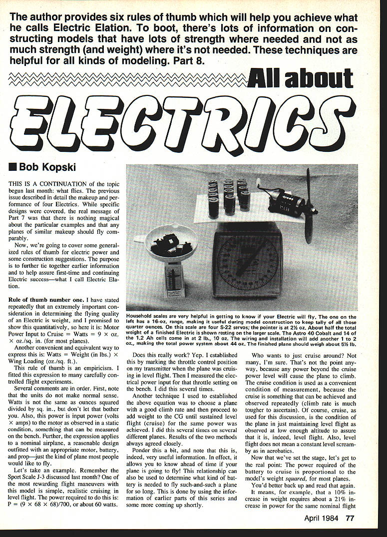
Practical tip: household scales are handy in construction — a small 16‑oz range scale helps keep track of quarter‑ounce increments; a larger scale is useful for the finished airplane.
Rule of thumb number two
- Motor input power (battery drain) required for ROG (run‑off‑ground) takeoff is about 30–50 watts per pound of nominal airplane.
Notes and examples:
- Variables include wing loading, wheel size, runway surface (hard runway vs. plush grass), and model ground handling.
- J‑3 example: gross weight ≈ 4.25 lb. Predicted takeoff power ≈ 4.25 × 30 W/lb ≈ 125 W. Typical system (Astro 15, belt drive, Top Flite 12×8) has input around 160 W at full throttle — easy takeoff.
- Superkick example: all-up weight 81 oz (~5.06 lb), wing loading ~17 oz/sq ft, small wheels — predicted ~250 W (≈50 W/lb); nominal operating 250–280 W — matches experience.
- Practical lower limit: about the smallest reliable power system for typical outdoor conditions is ~150 W, though exceptions exist.
Rule of thumb number three
- The electric power system components should make up about half the total weight of an RC Electric. Reasonable limits: 40%–60%.
Rule of thumb number four
- Wing weight guideline: a wing for an Electric RC model should weigh about 2 oz per sq. ft. Reasonable limits: 1.2–2.2 oz per sq. ft.
- Lower limit typical for smaller gliders; upper limit for aerobatic wings.
- These weights are for the complete wing structure (excluding servos and landing gear).
- Covering note: Super MonoKote weighs about 4 oz per sq. ft.; remember the covered area is twice the wing area.
Implicit in this guideline is the need for adequate strength. Lightness does not necessarily mean weakness if materials and techniques are used smartly.
Rule of thumb number five
- Think in quarter ounces: four quarter‑ounces make an ounce; four ounces make a quarter‑pound.
This is crucial. Small weight gains (a few ounces) significantly affect motor run time and flight performance. Watch servo choices, batteries, and construction details — quarter ounces add up.
Rule of thumb number six
- Forget most kits.
Rationale:
- Many glow‑engine kits are overbuilt because glow power and user habits tolerate extra weight. That extra pound or two often goes unnoticed with glow power but hurts electric performance.
- Exceptions: many glider kits adapt well to electric. Some kits are intended for Electric (examples seen by the author: Astro Porterfield, Astro Sport (shoulder‑wing), Leisure Playboy, Larry Jolly’s Electrics). Also, many magazine designs for Electric are excellent candidates, though they require scratch‑building skills.
If you have favorite glow plans, study them carefully before converting to Electric. Often scratch‑building or careful modification is the better route.
Some Construction Guidelines
Now that we've seen rules of thumb and some hard data, let's look beneath the covering.
Wings — three categories
I divide wings into three groups: gliders, aerobatic, and all‑purpose (Old Timer, Scale, Sport).
- Glider wings: relatively high aspect ratio; must support power installation mass. Weight is more critical for Electric gliders than for sailplanes that tolerate ballast and tow stresses.
- Aerobatic wings: lowest aspect ratio (“stubby”); often partial planking and very smooth surfaces; spars are often kept below covering level for smoothness.
- All‑other wings: blends of the techniques below.
A note on plug‑together wings: avoid if possible for Electric gliders because multi-piece wings usually carry a weight penalty.
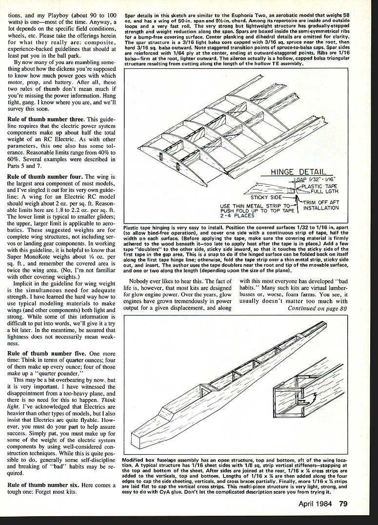
Spar and wing center construction (recommended approach)
Use a stepped, distributed-strength structure: main spars plus inner stub spars, webbing, and staggered spruce doublers that taper outward.
Key points:
- Use two main spars and two stub (partial‑span) spars (top and bottom for each pair). Stub spars can be partial span and the bottom stub spar may continue full span to support ribs.
- Web spars for part of their length; vary web coverage outward.
- Add spruce doublers of staggered lengths starting at the root and stopping at different rib stations — places spruce where strength is needed and avoid it where it’s not.
- Plank the center over one rib bay top and bottom before making the dihedral joint; sand mating surfaces flat for good end‑grain contact and epoxy gluing.
- Short full‑depth plywood dihedral braces glued to spruce doubler pieces produce a strong center joint.
- Result: very strong center section and gradually stepped reduction in strength and weight toward the tips.
Example (Spectra Soar wing):
- 8‑in chord, 67‑in span, rectangular planform, polyhedral.
- Main panels 20 in.; tip panels 13½ in.; ribs spaced 2½ in., 1/16 in. balsa.
- Four balsa spars 5/16 × 1/4 in.; stub spars ~12½ in.; webbing and spruce doublers 5/32 sq glued alongside balsa spars with staggered ending points.
- Wing area ≈ 536 sq in.; MonoKoted wing weight ≈ 6½ oz; supports a 39‑oz total weight plane. (This wing has been looped vigorously and has high strength in actual service.)
Larger wings use proportionally larger wood; smaller wings can be lighter. The idea is to use material conservatively but keep strength where it counts.
Tail assemblies
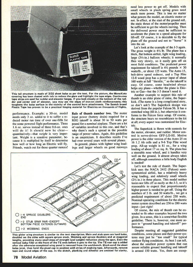
- Simple sheet balsa structures work well. Choose light, warp‑free wood and add hard capstrip material for strength and durability.
- Cap leading and trailing edges with hard balsa strips of the same thickness as the sheet and one to two times the thickness in width.
- Suggested sheet thickness:
- 3/32 in. sheet: adequate up to about 3–3½ lb models.
- 1/8 in. sheet: works fine up to about 6 lb.
- Built‑up tail structures can be lighter than solid sheet for similar durability. Use thin L.E./T.E. stock 1/8–1/4 in. thick and widths two to four times thickness.
Hinges
- Scotch Plastic Tape (not transparent tape) is an excellent hinge material when used correctly.
- Use 3/4‑in clear tape (Scotch P/N 210062) so the covering color shows through. It’s very light, strong, and durable over wide temperature ranges; the tape also closes hinge gaps when properly applied.
- The author has many hundreds of flights on these hinges with no fatigue issues.
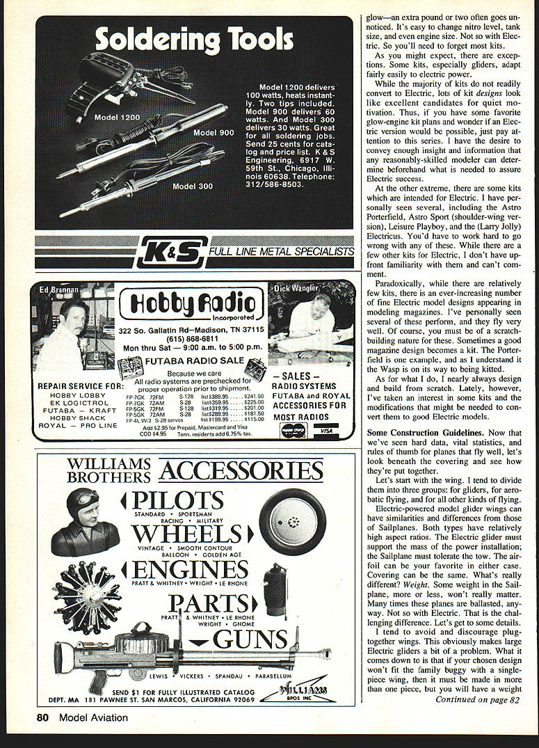
Fuselage construction
- Options: simple sheet box, modified sheet box (preferred), or all‑stick.
- Modified sheet box: sheet sides with partly open top and bottom to save weight while keeping necessary strength — a good “quarter‑scoring” approach.
- Use 1/16 in. sheet balsa sides up to about 3 lb models with partial doublers where needed. Be mindful of balsa grain and density.
Useful materials:
- 1/16 in. ply wing skin: adds strength with minimal weight — good for fuselage side doublers and motor mount lining.
- 1/8 in. Lite Ply: stronger/heavier than balsa but lighter than birch ply — ideal for formers in structural motor mounts and other places needing three‑ply lamina properties.
Adhesives and dihedral joints
- Most building done with CyA (CA) adhesives; epoxy (Hobbypoxy Formula 1 preferred) for dihedral joints and a few high‑stress areas.
- Dihedral joint technique: butt the wing center surfaces first (planking in place), sand mating surfaces flat, apply a thin smear of epoxy to soak in, wait 15–20 minutes, then apply fresh epoxy and glue the joint, holding for a few hours. Install dihedral braces afterward.
- Thoughtful material selection and fitting allow CA to do its job and epoxy to be used judiciously — results in lighter, stronger construction.
Covering
- Proper application of MonoKote (or similar plastic covering) to sheet structures adds significant finished strength. Smooth, evenly‑adhered covering helps; loose or bubbled covering does not.
- Spend extra care when covering sheet surfaces to gain this “free” structural benefit.
Building discipline
- Quarter‑ounce awareness and disciplined material selection are essential. Electrics tend to be heavier, so you must compensate by careful construction and avoiding “bad habits” that add unnecessary weight.
- Use scales during building: a small 16‑oz scale for parts and a larger scale for the finished airplane.
Final notes and future topics
- Next installment will survey motors, props, and batteries and their associated operating power levels. Combining those data with the rules of thumb here will help you plan successful Electrics.
- The author thanks readers for letters of appreciation and requests; reader input has guided some additions to this series.
Questions, comments, or requests (with SASE) may be directed to: Bob Kopski 25 West End Dr. Lansdale, PA 19446
Part 8 — Bob Kopski
Transcribed from original scans by AI. Minor OCR errors may remain.

