
All About Two-Cycle Engines
A definite update on the theory and design of modern model powerplants. The first of two parts. — Glenn Lee
Part One
Model fliers today are extremely lucky: we have a phenomenal amount of equipment and a number of good engines available at reasonable prices. Engines come in all sizes, and several are sold in versions suitable for RC, control line, free flight, or boats. We can readily obtain a powerplant for anything we wish to build.
There are so many engines available, however, that modelers new to the sport are often confused when it comes to buying one. Even some old timers do not understand terms used to describe the newest designs and innovations — terms such as Schnuerle porting, ABC, Dykes rings, ABCD, exhaust timing, squish-band, boost ports, etc. If you know everything about two‑cycle engines, there is no need for you to read this article. If, however, you would like a review of the design of our model engines, I will try to explain things thoroughly so even beginners can understand the differences in the various engines available. I will also review some of the newest engines that have come out in the last couple of years.
The basic design of model engines has not changed much since the first ones were built, but tremendous advancements have occurred in metallurgy and assembly. Most porting arrangements were patented back in the Thirties, so we cannot say they are very new. Machining tolerances and manufacturing techniques have progressed so far that finished dimensions of parts are held to a few millionths of an inch. These precise clearances between moving parts result in easy starting and long life as well as mass production assembly.
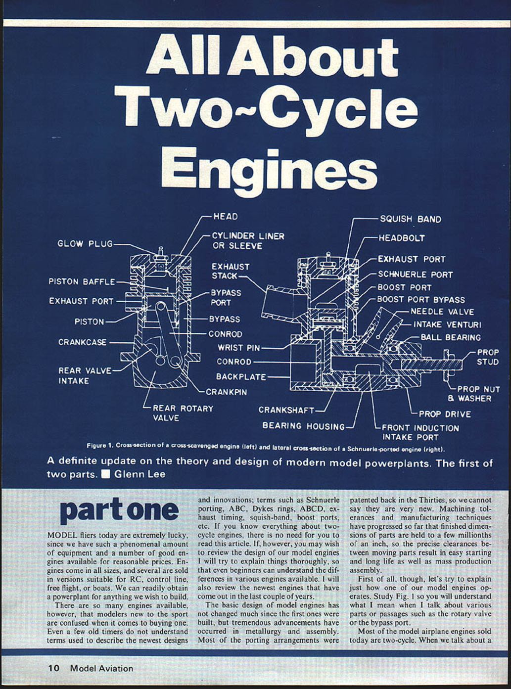
First of all, though, let's explain how a model two‑cycle engine operates. Study Fig. 1 so you will understand what I mean when I talk about various parts or passages such as the rotary valve or the bypass port.
Most model airplane engines sold today are two‑cycle. When we talk about a two‑cycle engine the piston traverses from one extreme (top dead center, TDC) to the other extreme (bottom dead center, BDC) and back again. In other words, a complete revolution of the crankshaft results in two cycles. A two‑cycle engine fires every revolution, while a four‑cycle engine (such as a big automotive engine) fires every other revolution.
Perhaps you are familiar with the four‑cycle engine and its parts and accessories such as cams, valves, oil pump, etc. The four‑cycle sequence is as follows:
- Start at TDC at the beginning of the exhaust stroke. As the piston moves down the exhaust valve is open and the intake valve is closed; fresh charge is drawn through the carburetor and manifold.
- After the piston reaches BDC it starts back up; the intake valve closes and the fuel‑air charge is compressed as the piston travels up to TDC.
- Near TDC the spark plug fires and combustion forces the piston down for the power stroke.
- The exhaust valve opens and the gases are forced out as the piston comes up during the fourth stroke.
Thus the intake, compression, power and exhaust strokes occur during two complete revolutions of the crankshaft. Four‑cycle engines burn an air‑fuel mixture and the lubricating oil must be contained in the crankcase and pumped or splashed around the moving parts. You can see why a four‑cycle engine needs such things as an oil pump, camshaft, valves, and a distributor or magneto for ignition.
Our two‑cycle engines have very few moving parts — just the piston assembly, conrod, crankshaft, and maybe a rotary valve. Some engines have a rear intake rotary valve; other engines have intake and exhaust openings (ports) which are opened and closed at the proper time as the piston reciprocates up and down. Intake air and fuel come into the crankcase through a carburetor and manifold. Lubrication is accomplished by mixing oil with the fuel; oil then reaches bearings and moving parts via the crankcase and transfer passages.
Two‑Cycle Operation (sequence)
- Start with the piston at BDC. As the piston moves upward it acts as a pump, creating negative pressure in the crankcase that draws a fresh charge of air and fuel through the carburetor and intake (rotary valve, reed, or piston port).
- The previous charge in the cylinder is compressed as the piston approaches TDC. The glow plug ignites the compressed charge near TDC and combustion forces the piston down for the power stroke.
- As the piston moves down, the intake rotary valve (or reed) closes, sealing the crankcase and allowing the piston to compress the charge drawn into the crankcase.
- Further downward travel opens the exhaust port first; burned gases begin to leave the cylinder.
- A little later the piston uncovers the bypass (transfer) ports, allowing the compressed crankcase charge to flow up into the cylinder. This fresh charge scavenges the cylinder, forcing burned gases out the exhaust and filling the cylinder with fresh mixture.
- The cycle then repeats.
Intake systems
- Rotary valve: Often used for best efficiency. A hole in the crankshaft (shaft induction) or a segmented disc actuated by the crankpin (rear‑intake rotary) times the intake opening. Intake timing can be designed for optimum performance.
- Reed valve: A thin springy sheet (brass or steel) that seals the intake and flexes open under crankcase vacuum. Reed valves improve idle and part‑throttle response by permitting flow in one direction only.
- Piston‑ported intake: The piston itself uncovers the intake port as it moves. This is the simplest and least expensive system but gives the poorest control of intake timing. Engines with unrestricted piston ports can often run in either direction.
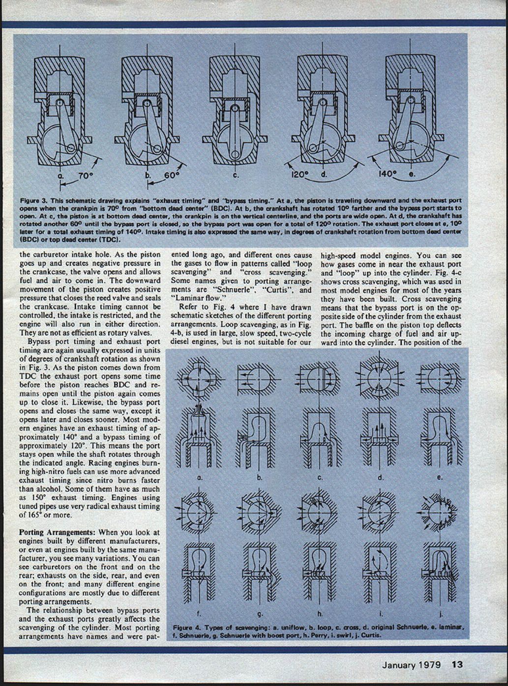
Port Timing
Intake timing, exhaust timing, and bypass (transfer) timing are usually expressed in degrees of crankshaft rotation. Typical values have been determined experimentally for each engine and application.
- Rotary valve timing example: A common sport/stunt timing is open at 45° ABDC (after bottom dead center) and close at 45° ATDC (after top dead center) — giving 180° intake timing. Racing engines may open at 35° ABDC and close at 60° ATDC, or 205° intake timing.
- Exhaust and bypass timing: Most modern model engines have exhaust timing about 140° and bypass timing about 120°. Racing engines burning high‑nitro fuels (nitro burns faster than alcohol) can use more advanced exhaust timing — some up to 150°. Engines using tuned pipes often use very radical exhaust timing (165° or more).
As the piston comes down from TDC the exhaust port opens before the piston reaches BDC and remains open until the piston comes back up. The bypass port opens later and closes sooner than the exhaust port.
Porting Arrangements
The relationship between bypass ports and the exhaust port greatly affects scavenging — the removal of burned gases and filling with fresh charge. Porting arrangements have names and typical gas‑flow patterns, such as "loop scavenging" and "cross scavenging." Common arrangements and characteristics:
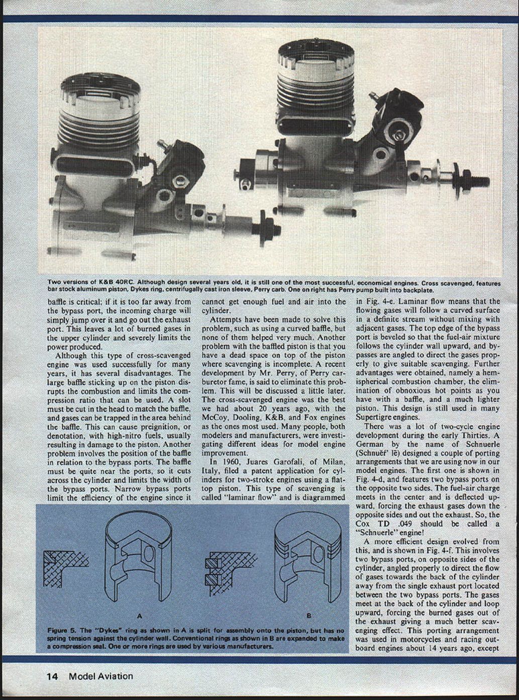
- Cross scavenging (traditional): Bypass ports are on the side opposite the exhaust port. A piston baffle deflects the incoming charge across the cylinder toward the exhaust. This arrangement was common in early model engines (McCoy, Dooling, K&B, Fox). Drawback: the piston baffle creates dead space and limits bypass port width.
- Loop scavenging: Used in larger, slow‑speed two‑cycle diesel engines; not suitable for high‑speed model engines. Gases flow in near the exhaust and loop up into the cylinder.
- Schnuerle porting: Invented by Schnuerle in Germany. There are variations:
- Two opposed bypass ports that meet and direct the flow upward, forcing exhaust down the sides and out the exhaust (early Schnuerle).
- A more efficient Schnuerle with two bypass ports angled toward the back of the cylinder and a single exhaust between them; the flows meet at the back and loop upward, improving scavenging.
- Schnuerle with an additional bypass (boost) port opposite the exhaust: the boost port angles upward to direct additional fresh mixture into the cylinder. Schnuerle porting with boost ports produces more power and greater efficiency because of increased bypass area and better scavenging.
- Laminar flow (flat‑top piston): Juarez Garofali (Milan, Italy) patented a flat‑top piston laminar flow approach in 1960. The bypass port top edge is beveled so the mixture follows the cylinder wall upward, reducing mixing and enabling a hemispherical combustion chamber, eliminating hot spots from piston baffles and allowing a lighter piston. Used in many Super Tigre engines.
- Perry Directional Porting (PDP): Consists of narrow bypass ports near the exhaust but directed away from it; reduces unscavenged "dead space" near the piston center. Can be used with Schnuerle or cross porting.
- Curtis porting: Several bypass ports are arranged and angled progressively so those near the exhaust are directed away and others angled upward, ending with a laminar flow type opposite the exhaust.
- Boost ports: Additional ports angled upward to increase charge directed into the combustion chamber.
- Uniflow porting: Uses an exhaust valve at the top of the cylinder opened by a camshaft so gases flow in one direction; very efficient at reducing mixing but more complicated than simple ported timing.
Historical notes:
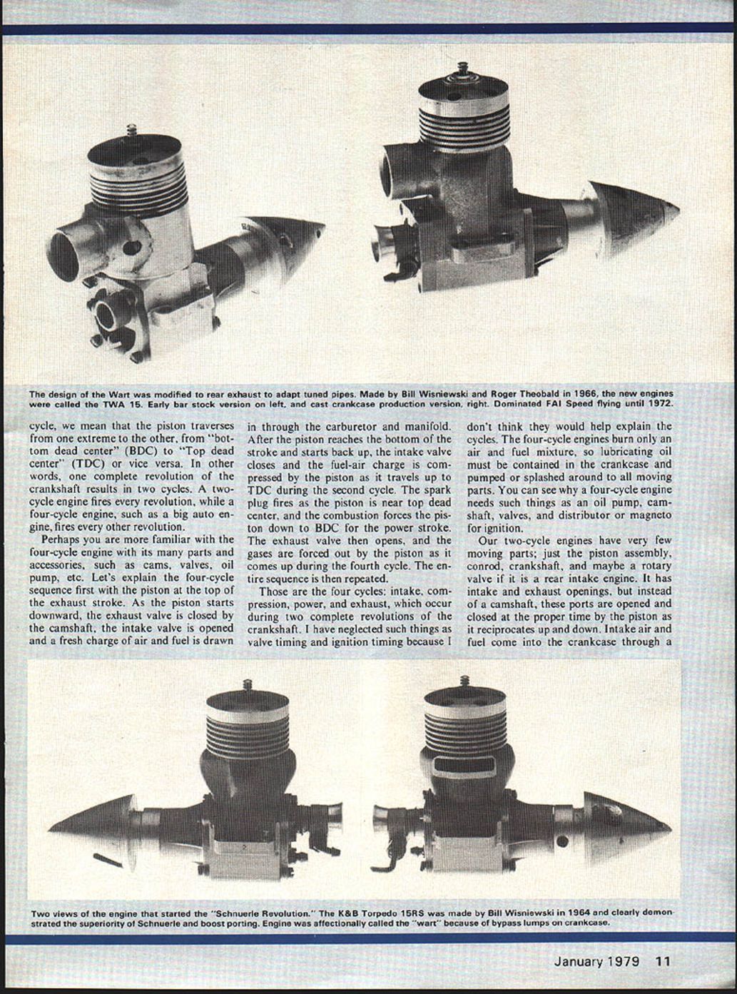
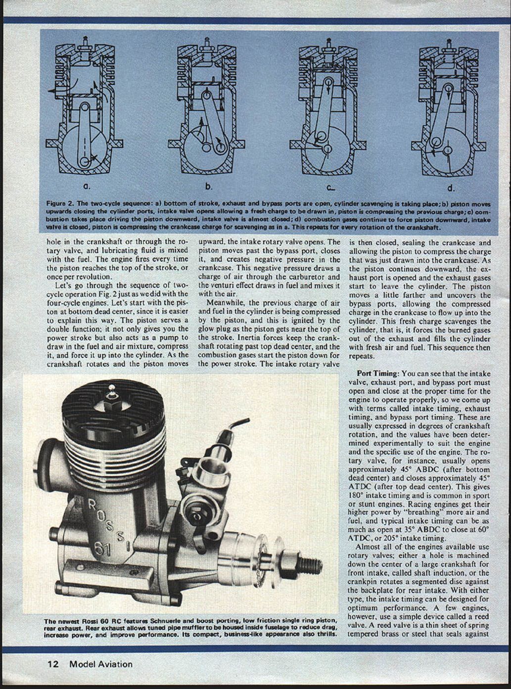
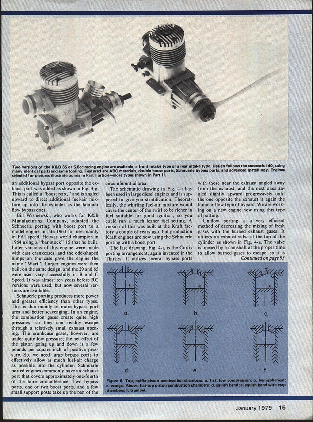
- Bill Wisniewski (K&B) adapted Schnuerle porting with a boost port for model engines in late 1963, producing successful racing engines (the "Wart" nickname came from odd case shapes). Schnuerle porting became widely adopted for its power and efficiency.
- Other experimental arrangements (e.g., stratifying swirl patterns) have been tested but the Schnuerle + boost arrangement has proven very effective in production.
Mechanical Improvements
Advances in metallurgy and manufacturing have significantly improved modern engines:
- Pistons: Now often machined from 2024‑T3 bar stock or forged rather than die‑cast. 2024 is harder and stronger with better hot strength than die‑casting alloys, giving increased rigidity, power, and wear life.
- Connecting rods: Made of forged 2024‑T3 aluminum, shot‑peened to increase strength and reduce stress concentrations.
- Heads: Machined from high‑strength alloys for resistance to warpage and better heat transfer.
- Crankshafts: Case‑hardened high‑strength alloy steels.
- Plating: Aluminum parts (backplates, etc.) can be nickel or chrome plated for wear resistance.
- Crankcases: Die cast or investment cast aluminum, heat treated for strength.
- Sleeves and rings: Where piston rings are used, rings are often high‑strength centrifugal cast iron used with chrome‑plated steel sleeves.
Many of these innovations were driven by control‑line speed competition where high nitro fuels demanded stronger alloys and better designs. Modern large RC engines can develop over 1.5 horsepower on 10% nitro fuels and run for hundreds of hours before significant wear.
Materials by size:
- Small engines (.19 displacement or less) often use cast iron pistons and free‑machining leaded steel sleeves — wear resistant and low friction but heavy.
- Larger engines (.40 displacement and up) use aluminum pistons for weight and balance reasons.
ABC and ABCD
- ABC: Aluminum, Brass, Chrome. A lapped aluminum piston (special high‑silicon alloy, 19–22% silicon) in a chrome‑plated brass sleeve. The high‑silicon aluminum has a low coefficient of thermal expansion, and the brass sleeve expands more when heated, maintaining proper clearances over operating conditions. This gives low friction, high power, long life, and little break‑in.
- ABCD: Aluminum, Brass, Chrome, Dykes ring. Similar construction but the piston (either high‑silicon casting or 2024‑T3) uses a single compression ring of the Dykes type rather than a lapped piston. The Dykes ring floats without spring tension and seals under combustion pressure only, reducing friction compared with a conventional springy ring.
Differences in idling characteristics between lapped ABC engines and ringed ABCD engines are possible (perhaps due to slight leakage at low rpm changing effective compression) but are generally minor.
Combustion Chambers
Combustion chamber shape affects performance and tendency to preignition:
- Flat‑top piston with a well‑designed chamber eliminated much preignition, allowing high compression and high nitro fuels (up to 80% nitro in racing events).
- The most successful high‑performance chamber shape used in many Schnuerle‑ported engines features a domed chamber with a squish band: a flat area around the periphery set very close to the piston at TDC. The squish band forces the mixture into the domed chamber, producing high turbulence and improved combustion efficiency.
- The distance from the top of the piston to the glow plug strongly affects engine temperature and plug performance.
- Trumpet chambers (used in Cox and Rossi high‑performance engines) also work well.
- Some "hop‑up" modifications alter the squish band; however, similar or better performance is typically achieved by setting the head clearance for optimum compression ratio and adjusting for weather conditions where necessary.
- Sport and RC engines are less sensitive to weather changes, so compression adjustments are rarely needed for them. A good tachometer is necessary when varying head clearance to measure rpm and find the best setting.
This ends part one; next month we will cover tuned pipes and general descriptions of several new engines on the market.
Transcribed from original scans by AI. Minor OCR errors may remain.

