
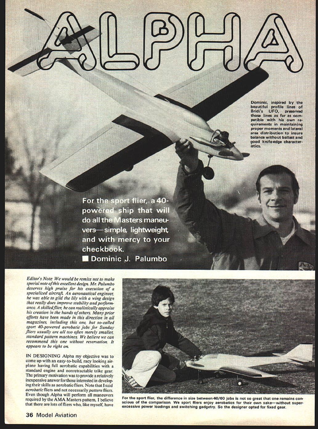
Alpha
Dominic J. Palumbo
Editor's Note
We would be remiss not to make special note of this excellent design. Mr. Palumbo deserves high praise for his execution of a specialized aircraft. An aeronautical engineer, he was able to gild the lily with a wing design that really does improve stability and performance. A skilled flier, he can realistically appraise his creation in the hands of others. Many prior efforts have been made in this direction in all magazines, including this one, but so-called sport 40-powered aerobatic jobs for Sunday fliers usually are merely smaller, standard-pattern machines. We believe we can recommend this one without reservation. It appears to be right on.
Introduction
In designing Alpha my objective was to come up with an easy-to-build, racy-looking airplane having full aerobatic capabilities with a standard engine and nonretractable trike gear. The primary motivation was to provide a relatively inexpensive answer for those interested in developing their skills as aerobatic fliers. Note that I said acrobatic fliers and not necessarily pattern fliers. Even though Alpha will perform all maneuvers required by the AMA Masters pattern, I believe there are lots of fliers who, like myself, have neither the time, desire, nor bankroll necessary to become serious contenders in pattern competition.
So-called sport fliers enjoy aerobatic flying for its own sake—without super-excessive power loadings and switching gadgetry. Alpha was designed to look fast, fly fast, and yield snappy performance at a cost much less than a typical full-blown pattern aircraft.
Evolution of the Design
Among the many factors that enter into the design of highly aerobatic aircraft, two stand out as most important: drag and weight. Every aircraft is a unique compromise of these factors, but the vertical-maneuver capabilities which aerobatic aircraft must possess make these two factors increasingly important.
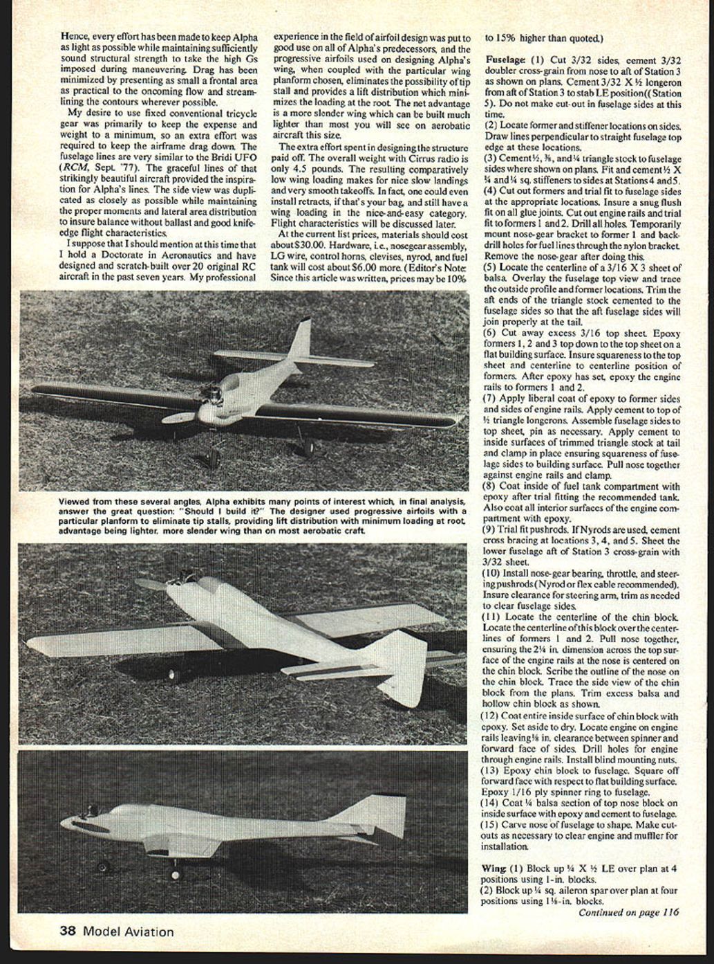
Effort was made to keep Alpha as light as possible while maintaining sufficiently sound structural strength to withstand the high Gs imposed during maneuvering. Drag has been minimized by presenting a small frontal area to the oncoming flow and by streamlining contours wherever possible.
Because I desired to use fixed, conventional tricycle gear primarily to keep expense and weight to a minimum, extra effort was required to keep airframe drag down. The fuselage lines are very similar to the Bridi UFO (RCM, Sept. ’77); its graceful lines and striking beauty provided inspiration. Alpha’s side-view lines were duplicated as closely as possible while maintaining proper moments and lateral-area distribution to ensure balance, ballast, and good knife-edge flight characteristics.
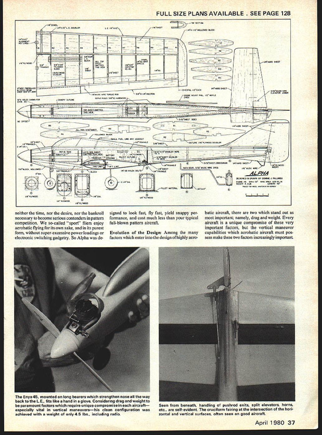
I hold a doctorate in aeronautics, have designed and scratch-built over 20 original R/C aircraft during the past seven years, and have professional experience in the field of airfoil design. I put this experience to good use: Alpha’s predecessors and progressive airfoils were used in designing Alpha’s wing. The progressive airfoils, coupled with the chosen wing planform, eliminate the possibility of tip stall and provide a lift distribution that minimizes loading at the root. The net advantage is a more slender wing which can be built much lighter than most you will see on an aerobatic aircraft this size.
The extra effort spent in designing the structure paid off. The overall weight with Cirrus radio is only 4.5 pounds. The resulting comparatively low wing loading makes for nice slow landings and very smooth takeoffs. One could even install retracts and still have a wing loading in the easy category. Flight characteristics are discussed later.
At current list prices materials should cost about $30.00. Hardware (nosegear assembly, LG wire, control horns, clevises, nylon, and fuel tank) will cost about $6.00 more. (Editor's Note: Since this article was written, prices may be 10% to 15% higher than quoted.)
Construction
Fuselage
- Cut 3/32" sides; cement 3/32" doubler cross-grain from nose to aft of Station 3 as shown on plans. Cement 3/32" x 5/16" longeron from aft of Station 3 to stab LE position (Station 5). Do not make cut-out in fuselage sides at this time.
- Locate former and stiffener positions on sides. Draw lines perpendicular to straight fuselage top edge at these locations.
- Cement 1/2", 3/8", and 1/4" triangle stock to fuselage sides where shown on plans. Fit and cement 1/2" x 1/4" and 3/4" x 1/4" stiffeners to sides at Stations 4 and 5.
- Cut out formers and trial-fit to fuselage sides at the appropriate locations. Ensure a snug flush fit on all glue joints. Cut out engine rails and trial-fit to formers 1 and 2. Drill all holes. Temporarily mount nosegear bracket to former 1 and back-drill holes for fuel lines through the nylon bracket. Remove the nosegear after doing this.
- Locate the centerline of a 3/16" x 3/8" sheet of balsa. Overlay the fuselage top view and trace the outside profile and former locations. Trim the aft ends of the triangle stock cemented to the fuselage sides so that the aft fuselage sides will join properly at the tail.
- Cut away excess 3/16" top sheet. Epoxy formers 1, 2, and 3 top-down to the top sheet on a flat building surface. Ensure squareness to the top sheet and centerline-to-centerline position of formers. After epoxy has set, epoxy the engine rails to formers 1 and 2.
- Apply a liberal coat of epoxy to former sides and sides of engine rails. Apply cement to top of 1/2" triangle longerons. Assemble fuselage sides to top sheet; pin as necessary. Apply cement to inside surfaces of trimmed triangle stock at tail and clamp in place, ensuring squareness of fuselage sides to building surface. Pull nose together against engine rails and clamp.
- Coat inside of fuel tank compartment with epoxy after trial-fitting the recommended tank. Also coat all interior surfaces of the engine compartment with epoxy.
- Trial-fit pushrods. If Nyrod(s) are used, cement cross bracing at locations 3, 4, and 5. Sheet the lower fuselage aft of Station 3 cross-grain with 3/32" sheet.
- Install nose-gear bearing, throttle, and steering pushrods (Nyrod or flex cable recommended). Ensure clearance for steering arm; trim as needed to clear fuselage sides.
- Locate the centerline of the chin block. Center this block over the centerlines of formers 1 and 2. Pull the nose together, ensuring the 2-1/4" dimension across the top surface of the engine rails at the nose is centered on the chin block. Scribe the outline of the nose on the chin block. Trace the side view of the chin block from the plans. Trim excess balsa and hollow chin block as shown.
- Coat the entire inside surface of the chin block with epoxy. Set aside to dry. Locate engine on engine rails leaving 1/8" clearance between spinner and forward face of sides. Drill holes for engine through engine rails. Install blind mounting nuts.
- Epoxy chin block to fuselage. Square off forward face with respect to flat building surface. Epoxy 1/16" ply spinner ring to fuselage.
- Coat 1/4" balsa section of top nose block on inside surface with epoxy and cement to fuselage.
- Carve nose of fuselage to shape. Make cutouts as necessary to clear engine and muffler for installation.
Wing
- Block up 1/4" x 1/4" LE over plan at four positions using 1" blocks.
- Block up 3/8" square aileron spar over plan at four positions using 1-1/4" blocks.
- Using a square, project the locations of the ribs up from the plan and mark these locations on the LE and aileron spar. Mark off the centerline of the LE and aileron spar at each rib location.
- Glue ribs between LE and aileron spar so that centerline of rib coincides with centerlines of LE and aileron spar at each location. Ensure squareness of ribs to building surface using a square.
- Cement 1/4" x 1/4" LE doubler between R1 and R2.
- Cement 1/4" square spruce spars into notches in ribs.
- Cement 1/16" balsa LE and TE sheeting. For the right-hand wing panel (cut-outs in R2, R3 and R4 for LG block facing down) also sheet the centersection from R1 to R4 before turning the panel over.
- Turn the panel over. Reposition the support blocks, and sheet the LE and TE.
- To make the left-hand panel, repeat steps 1 through 7 except that now the cut-outs in R2, R3 and R4 will face up. Do not sheet the centersection before turning the left panel over. Turn the left panel over, reposition the support blocks, sheet the LE and TE. Sheet the centersection.
- If you've followed instructions correctly up to this point, you should have a right and left wing panel, with the tip of each centersection sheeting even with the bottom of each centersection not sheeted. Now epoxy the 1/16" ply rib web doubler to R2 and R4.
- Install LG (landing gear) blocks, trunnion blocks with 3/8" triangle on either side, and 1/16" ply dowel support between the spars between R1 and R2. Trial-fit the 5/32" landing gear before sheeting the undersides of each panel. Note that the centersection sheeting on the underside should extend out to the end of the LG block; that is, about 1/2" beyond R4.
- Cement 1/4" x 1/16" cap strips to R5 through R1. Wing tip blocks are carved, hollowed, and cemented to each panel as shown.
- Bend torque rods for ailerons using 1/8" music wire. Use a piece of 5/32" aluminum tubing for a bearing around the torque rods. The 1/8" wire will fit nicely into a standard piece of K&S 5/32" tubing. Notch the trailing edge to accept the torque rods.
- Cement the trailing edge with the torque rods inserted into the wing panels. Be extremely careful to maintain alignment of the torque rods while the cement sets. Ensure the trailing edge is positioned symmetrically about the centerline of the airfoil section before the glue hardens. Use masking tape to keep the TE position from changing while the glue hardens.
- Trial-fit the ailerons to the wing panels. Insert hinges into the aileron spars and locate corresponding slots in the ailerons. Drill and notch the inboard sections of the ailerons to accept the torque rods. Make sure the ailerons move easily before final installation.
- Before joining the wing panels, shape the LE carefully and sand the dihedral angle into the center joint of each panel. Cement the 1/4" x 1/8" alignment blocks into one of the panels. Apply epoxy to the joining surfaces and cement the panels together. Cover the centersection joint with a 4" wide piece of 6 oz. fiberglass filled with epoxy or resin.
Tail Surfaces
- Cut vertical and horizontal stabilizers from 1/4" hard balsa sheet. Taper elevator and rudder and shape fin and stab leading edges to form an airfoil-like contour.
- Install and pin hinges into the stationary portion of each and make corresponding slots in elevator and rudder to accept hinges.
- Cement 1/8" pine insert into rudder for control horn as shown on the plan. If a flap control horn is used to join the elevator halves, no pine insert is needed. If 3/32" medium-weight balsa (MW) is used, cement a pine insert into one of the elevator halves at the control horn location desired.
- Install elevator joiner (or flap control horn) into elevator halves. To ensure alignment of the two halves, drill an oversized hole for the joiner, fill with epoxy, and join on a flat surface covered with wax paper.
- The elevator is permanently hinged to the forward stab and the centerpiece epoxied in place. Coating the joiner with Vaseline prior to epoxying the centerpiece in place will ensure the joiner is not epoxied to the stab.
Final Assembly
- Final-shape the rear top portion of the fuselage. Cut the 1/8" slots for the horizontal stab as shown on the plan. Cement the horizontal stab to the fuselage. True alignment is obtained by laying the fuselage on its top over the plan and locating the elevator hinge line over the location shown. With the fuselage top flat on the building surface, place a piece of scrap 3/16" balsa under each end of the stab and pin everything down.
- The sub-fin is cemented to the fuselage while the horizontal stab is drying. Shape the rear lower fuselage prior to gluing the sub-fin in place. Ensure squareness of the sub-fin to the building surface and that it is centered on the fuselage.
- The 1/8" plywood wing hold-down is now cemented to the fuselage. Be sure to epoxy 1/4" triangular stock pieces at the junctions between the fuselage sides and former number 3.
- Locate the centerline of the wing over the centerline of the fuselage. Ensure precisely the same height off the building surface to the leading and trailing edges (this will yield zero incidence). Adjust the fuselage cut-outs accordingly to ensure true alignment with the horizontal stab.
- Locate the holes in the leading edge for the 1/8" hard dowels. Drill 1/4" diameter holes all the way through the 1/16" plywood dowel supports aft of the main spars. Insert the dowels and epoxy in place.
- With the wing properly aligned, drill #7 holes at the location of the nylon bolts. Drill through the 1/8" hold-down plate. Remove the wing, tape the holes in the hold-down plate, open the holes in the wing trailing edge to 1/4" diameter. Replace the wing, bolt in place using 1/4-20 nylon bolts. Fairings at the leading and trailing edges are built up and sanded to shape.
- Cement the fin and canopy blocks to the fuselage, ensuring that they are properly centered. Sand and shape the fuselage to the contours shown on the plans; build up fillets as desired using your favorite filler (the author prefers Epoxolite).
- Apply your favorite finish but keep it as light as possible.
- Install landing gear, fuel tank, engine, and all pushrods. Make sure the nose wheel is adjusted so that the wing sits at zero incidence (level to the ground). Install radio to achieve the desired CG location. Locate CG at the position shown on the plans for less sensitivity to elevator deflection. Full acrobatic capabilities exist when CG is positioned as shown.
Finishing
Use your favorite covering method but keep it as light as possible. The author used Solarfilm to cover the wings and tail surfaces, while the fuselage was covered with silk, with three coats of clear dope, and two coats of Formula-U.
Flying Alpha
Alpha tracks like she's riding on rails. Flat-out airspeed is 70+ mph, while landing airspeed is a mere 20 mph. A standard Enya .45 with Tatone muffler is all that is needed. Several props were tried, including:
- Zinger 10-6
- Top Flite 10-6 and 11-4 (Standard and Super-M)
- Tornado Nylon 10-6
- Top Flite Nylon 10-6
Best performance was obtained with the Standard Top Flite 10-6. It was noted that several flights were made using the Enya .45 muffler and a noticeable increase in performance was evident upon switching to the Tatone muffler. A tuned pipe would probably increase the effective power output even more, but the aircraft is capable of all Masters pattern maneuvers without the pipe.
As with any aircraft, sensitivity to controls is a strong function of CG location. Fore and aft limits are shown on the plan, and having tested the aircraft at all locations between these limits, the recommended position is shown. Further aft of this, the plane is too sensitive to elevator deflection and wind gusts; more forward leads to more sluggish elevator response and spins resembling vertical diving stalls.
A moderately flat spin is achieved with the CG positioned as shown, full up elevator, and opposite rudder and aileron. Recovery is extremely quick and smooth upon neutralizing the controls. Snap-rolls pose no problem. Perhaps the most impressive stall turns observed were achieved with Alpha: apply rudder a fraction of a second before throttling back and watch Alpha perform one of the flattest turns you’ll ever see. Inverted and knife-edge flight characteristics are good, with no observable bad tendencies. A slight amount of up elevator is required in the knife-edge position to keep the plane tracking straight.
Build Alpha properly and you're in for some very pleasant aerobatic flying at a fraction of the cost.
Transcribed from original scans by AI. Minor OCR errors may remain.

