
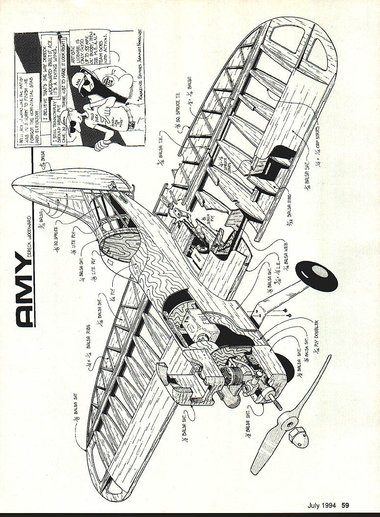
AMY
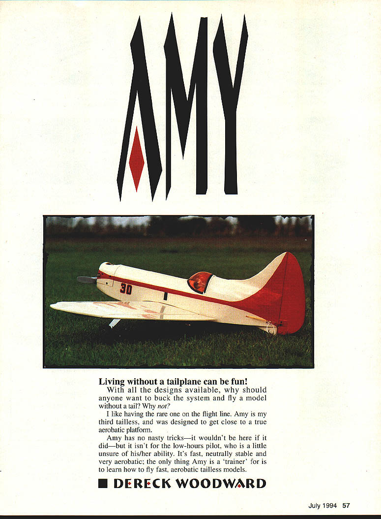
Living without a tailplane can be fun!
With all the designs available, why should anyone want to buck the system and fly a model without a tail? Why not? I like having the rare one on the flight line. Amy is my third tailless and was designed to get close to a true aerobatic platform.
Amy has no nasty tricks — it wouldn't be here if it did — but it isn't for the low‑hours pilot who is a little unsure of his/her ability. It's fast, neutrally stable and very aerobatic; the only thing Amy is a 'trainer' for is to learn how to fly fast, aerobatic tailless models.
■ DERECK WOODWARD
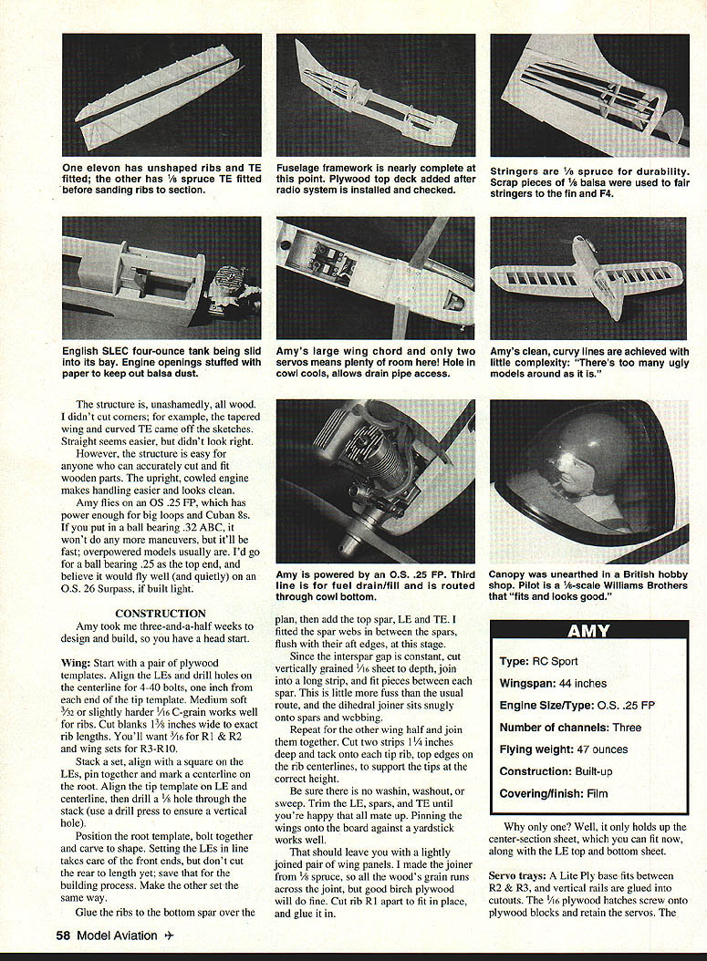
The structure is, unashamedly, all wood. I didn't cut corners; for example, the tapered wing and curved trailing edge came off the sketches. Straight seems easier, but didn't look right. However, the structure is easy for anyone who can accurately cut and fit wooden parts. The upright, cowled engine makes handling easier and looks clean.
Amy flies on an O.S. .25 FP, which has power enough for big loops and Cuban 8s. A ball‑bearing .32 would make it fast and rather overpowered — it won't improve manoeuvres. I'd go for a ball‑bearing .25 as the top end, and believe it would fly well (and quietly) on an O.S. 26 Surpass if built light.
SPECIFICATIONS
- Type: R/C Sport
- Wingspan: 44 inches
- Engine size/type: O.S. .25 FP
- Number channels: Three
- Flying weight: 47 ounces
- Construction: Built‑up wood
- Covering/finish: Film
CONSTRUCTION
Amy took three‑and‑a‑half weeks to design and build, so you have a head start.
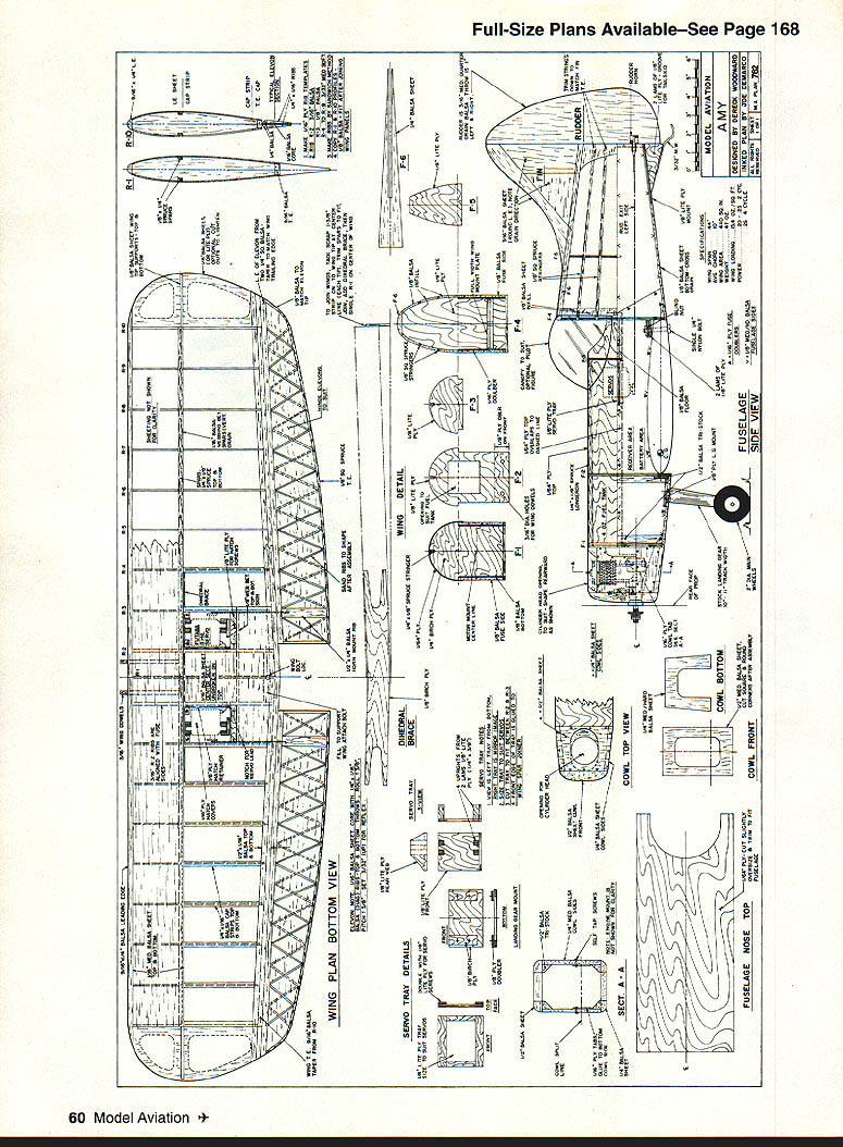
Wing
- Start with a pair of plywood templates. Align the leading edges (LEs) and drill holes on the centreline for the 4‑40 bolts at the outer end of the tip template.
- Use medium‑soft 3/32" or slightly harder 1/16" C‑grain stock for the ribs. Cut blanks 1‑3/8" wide to the exact rib lengths shown on the plan. Make R1 & R2 as specified on the plan and stack the remaining ribs (R3–R10) for template work.
- Stack a set, align the square LEs, pin together and mark the centreline at the root. Align the tip template on the LE and centreline, then drill a vertical hole through the stack (use a drill press to ensure a true vertical hole).
- Position the root template, bolt the stack together and carve to shape. Setting the LEs in line takes care of the front ends; do not cut the rear to final length yet — save that for the building process. Make the other wing half the same way.
- Glue the ribs to the bottom spar over the plan, then add the top spar, LE and TE. Fit spar webs between the spars, flush with their aft edges.
- Since the inter‑spar gap is constant, cut vertically grained 1/16" sheet to depth, join into a long strip and fit pieces between each spar. This makes the dihedral joiner sit snugly onto spars and webbing.
- Repeat for the other wing half and join them together. Cut two small strips and tack them onto the tip rib top edges at the rib centrelines to support the tips at the correct height.
- Check carefully for washin, washout and sweep. Trim the LE, spars and TE until all mating surfaces are true. Pin the wings onto a building board against a yardstick for accurate alignment.
- Make the joiner from 1/8" spruce; if the grain runs across the joint use good birch plywood instead. Cut rib R1 apart to fit over the joiner and glue it in place.
- Fit the centre‑section sheet and the LE top and bottom sheets once the join is secure.
Servo trays
- A lite‑ply base fits between R2 & R3. Glue vertical rails into the cutouts.
- 1/16" plywood hatches screw onto plywood blocks and retain the servos.
- Only one hatch is needed to support the centre‑section sheet and to allow access to the servos.
Fuselage
- The fuselage framework is nearly complete at this point. Add the plywood top deck after the radio system is installed and checked.
- Stringers are 1/8" spruce; use scrap pieces as fairing stringers. Spruce is more crush‑resistant than balsa and looks sharper when covered.
- Glue the 1/4" top deck onto the fin and attach that assembly to the top of F4 and the fuselage rear. When set, add the 1/8" square spruce stringers.
- The fin is F4. An English SLEC four‑ounce fuel tank slides into its bay. Stuff engine openings with paper while sanding to keep out balsa dust.
- Amy's large wing chord and two servos mean plenty of room. A hole in the cowl provides cooling and allows drain pipe access. The third‑line fuel drain/fill is routed through the cowl bottom.
- The canopy was sourced from a British hobby shop; the pilot is a scale Williams Brothers figure and fits well.
Wheels and undercarriage
- Small wheels are preferable; they create less drag. I use two‑inch Sullivan Skylite wheels on short, rough grass.
RADIO AND CONTROL SETUP
This model was designed around Futaba FF7 computer gear for elevon mixing, hence the wing servos drive each elevon directly. If you don't have such a transmitter, a dedicated elevon mixer (mechanical or electronic) like Ace R/C's Christie Mixer can be used.
With many electronic options for elevon mixing available, I didn't use a mechanical mixer. There is ample room in the fuselage if you prefer one.
Notes:
- Ensure adequate clearance between the wing‑mounted moving parts and fixed items in the fuselage cavity.
- Use heavy‑duty torque rods; the elevons are larger than ailerons on a comparable conventional model.
- The receiver goes in the forward top deck atop a flat Ni‑Cd four‑pack, suitably padded. You'll need two extension leads for the elevon servos — mark them and their matching servo leads.
If Amy is your first elevon‑equipped model, be methodical in setting up. I recommend setting up the controls before covering. Try this sequence:
- Mount gear, switch on to establish servo neutrals, set servo arms and pushrod lengths to achieve an elevon position of 3½° up (at the elevon TE) from neutral. "Neutral" is with the elevon lower surface parallel to the fuselage bottom.
- Move the elevator stick and establish a "pitch" throw of 1/4" each way.
- When happy with pitch, set "roll" to 3/8" each way by moving the aileron stick only. At this stage, the controls move in the same manner as on a conventional aircraft.
- Check for "full and free." Move the controls through their full combined range to ensure nothing binds. For example, "full up and left" should move the left elevon up about 5/8" at the root TE datum, with the rest of the surface moving in due proportion.
You can tweak throws later to suit your style. I set the rudder to move about 1" each way as a starting point.
FINISH
- I recommend a film covering material to keep the weight down; the structure is stiff enough that the covering is cosmetic rather than structural.
- Keep the colour scheme bright with good "this way up" clues.
- The colour used on my example was British Solarac and Solartrim; any compatible paint or adhesive trim will do.
BALANCE AND FLIGHT PREPARATION
- An aft centre of gravity will result in an unrecoverable departure from controlled flight. Balance the model accurately before leaving home.
- Do not accept "near enough" when balancing on the flying field. Use a proper balancer — the trivial difference between perfectly trimmed and slightly tail‑heavy can be enormous in effect.
FINAL NOTES
- Amy is fast, neutral and very aerobatic. It's not a beginner's first model but is rewarding for a pilot confident with elevon flying and higher speeds.
- Build the structure light where possible if you plan to use the quieter O.S. 26 Surpass or to keep wing loading modest.
Transcribed from original scans by AI. Minor OCR errors may remain.

