
Anne's Plane
By Ron McNally
Overview
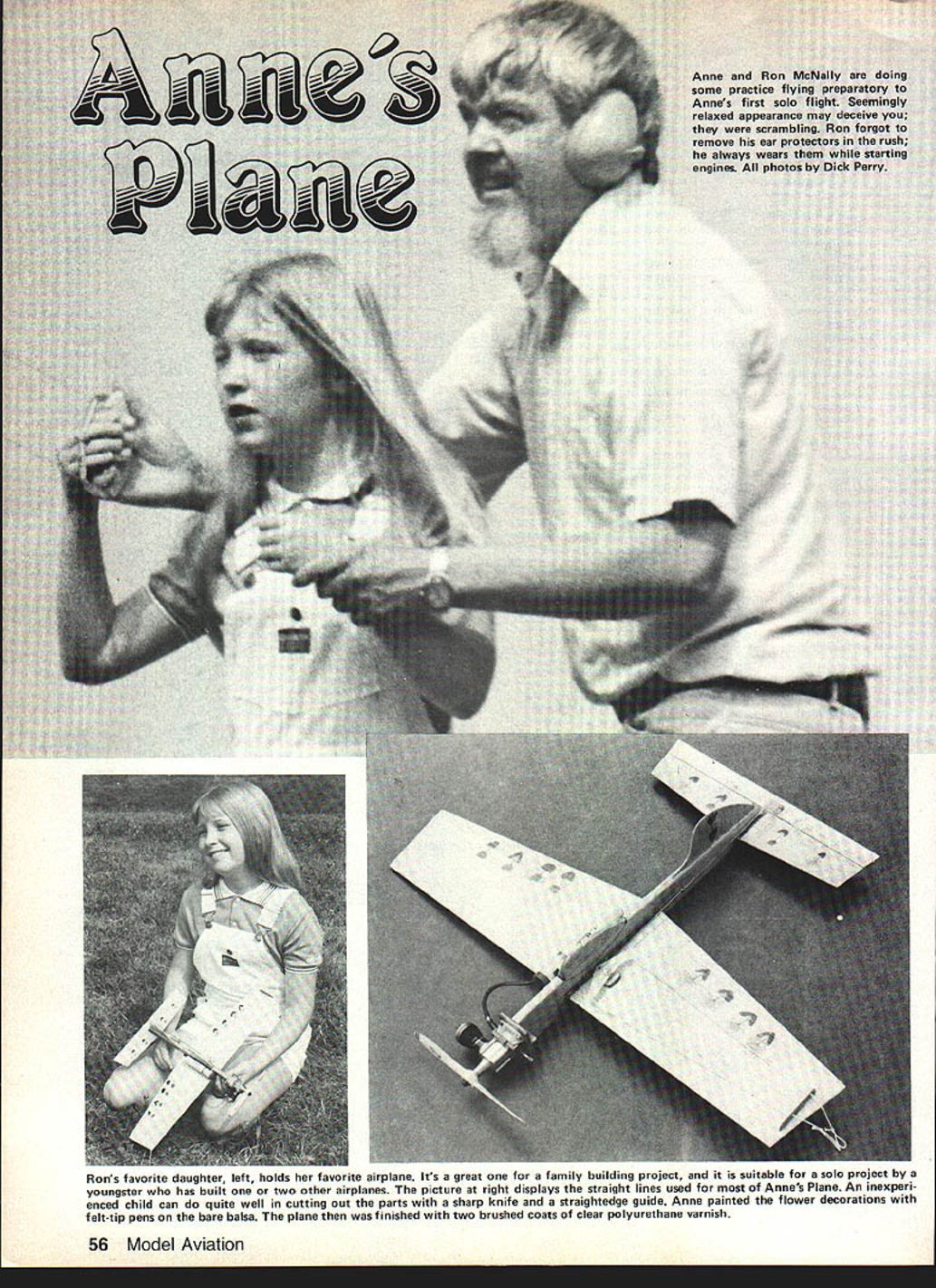
When my daughter Anne, age eight, decided she wanted to build a small control-line (CL) airplane we could make together, the inspiration was a $2.15 bag of odds-and-ends balsa. Sorting the shavings, Anne found several light, flat sheets of 1/16-in balsa—just right for a small slab-wing airplane. One idea led to another; soon we were sketching wing, stab, elevator and fuselage shapes, seeking Anne's approval as we went. Simplicity, interesting appearance, and easy flying qualities were the criteria.
The build is straightforward and nearly foolproof for wing/stab alignment because fuselage construction uses two 3/16 x 3/4-in spacers. The 1/16-in material for many parts keeps the model light and less prone to damage; 1/8-in wood can be used but is more likely to break. This is an excellent joint project for parent and child and also a good solo project for a youngster who has built one or two models previously.
Anne decorated the plane with felt-tip pens on the bare balsa and finished it with two brushed coats of clear polyurethane varnish.
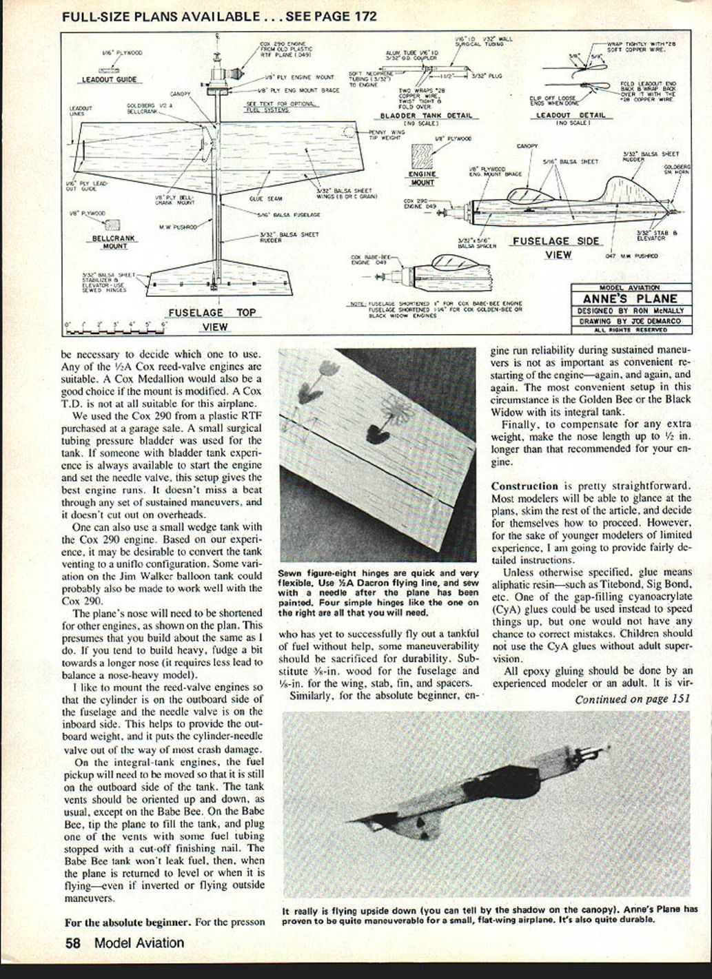
FULL-SIZE PLANS AVAILABLE. SEE PAGE 172.
Engine
Recommended engines
- Suitable: Cox reed-valve .049 (1/2A) engines such as the Cox 290, Babe Bee, Golden Bee, or Black Widow.
- Not suitable: Cox T.D.
- Possibly suitable: Cox Medallion with mount modification.
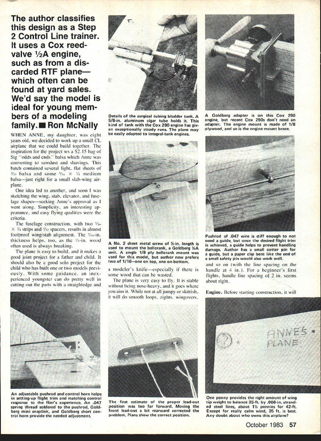
Discarded RTF planes (often found at yard sales) are a good source for a Cox .049 engine. The Cox 290 has given exceptionally steady running in this model. Recent Cox 290s usually do not require an adapter used with older engines.
Mounting and tanks
- Engine mount: made from 1/8-in plywood. Orient mount long-side-vertical or long-side-horizontal depending on the engine used.
- Integral-tank engines: the engine-mount brace can be adapted to work with these; move the fuel pickup so it remains on the outboard side of the tank.
- Bladder tank: a small surgical-tubing pressure bladder works well. A small syringe (10 cc) and a clamp are useful to fill and pinch off the fuel line.
- Alternative tanks: small wedge tank or balloon-type tanks can be used; uniflow venting may improve reliability with some setups.
Mount reed-valve engines with the cylinder on the outboard side of the fuselage and the needle valve inboard to help with outboard weight and to protect the needle valve from crash damage.
Details / Hardware
- Bellcrank mount: originally a single 1/8-in ply mount (Goldberg AA unit); the author prefers two 1/16-in ply mounts (one top, one bottom).
- Bellcrank mounting screw: No. 2 sheet-metal screw, ~3/8-in length (or 1/4-in in some descriptions).
- Engine mount brace: 1/8-in plywood, ~1-1/4 to 1-1/2 in long depending on engine.
- Pushrod: .047-in piano wire is stiff enough for flight loads.
- Pushrod guide: small cotter-pin guide, bent paper clip, or a small safety-pin-style guide works well.
- Control hardware: Goldberg mini snaplink and short control horn recommended for adjustable linkage.
- Leadouts: 0.008-in stranded steel lines, 35 ft is typical; 42 ft can be used in very calm conditions.
- Wing-tip weight: a penny glued under the wing tip provides the correct wing-tip weight balance on the author’s model.
Construction
Unless otherwise specified, "glue" refers to aliphatic resin (Titebond, Sig Bond, etc.). Gap-filling cyanoacrylates (CyA) can speed assembly but give little time for correction; children should not use CyA without adult supervision. All epoxy work should be done by an experienced modeler or adult. Avoid inhaling sanding dust and minimize skin contact with epoxy.
It helps to do a dry run of the fuselage assembly before gluing anything permanently.
Materials and basic stock
- 1/16-in balsa sheets: for wing, stab, fin
- 2-in and 3-in strips of 1/16 x 36-in balsa for wing lamination (see Wing section)
- 5/16 x 3/4 x 36-in medium-hard balsa for fuselage sides (cut to length)
- 3/16 x 3/4-in spacers (two pieces; rear spacer ~4 in, front spacer ~1-1/16 in, adjust per engine)
- 1/8-in plywood: engine mount, bellcrank mount (or use 1/16 ply for two pieces)
- 1/16-in plywood: small parts such as line guide, bellcrank mounts (if using two)
- Misc: soft copper wire, sheet-metal screws, small pieces for canopy, soft neoprene tubing for bladder tank, etc.
Wing
- Use two sheets (one 2-in and one 3-in) of 1/16 x 36-in balsa to make a lamination rather than finding a single wide sheet.
- Cut both sheets to an 18-in length.
- True up one edge of each sheet with a sharp knife and straightedge so the edges match squarely.
- Tape the two sheets together along the seam, open them, apply glue in the joint, then pin tape-side-down on a flat board to dry overnight.
- When dry, remove tape and sand the seam smooth with 320 paper.
- Measure and cut wing outline with a sharp knife and straightedge; do not round leading and trailing edges yet.
Stabilizer and elevator
- Cut stab and elevator from remaining 2-in sheet.
- Tape stab and elevator together (do not glue) prior to cutting outlines for accuracy.
- Finish shapes with a straightedge and sharp knife.
Vertical fin
- Glue together three pieces of 1/16-in sheet to form the fin, using remaining 2-in sheet and trimmed material.
- Ensure the grain is vertical.
- Cut oversize, especially toward the front, and sand to final outline after gluing to the fuselage.
Fuselage
- Select straight 5/16 x 3/4 x 36-in medium-hard balsa and cut two pieces about 12 in long (or leave longer and trim after assembly).
- Cut spacers from scrap balsa: rear spacer ~4 in, front spacer ~1-1/16 in (shorter for some engines).
- Cut canopy block from 3/16 x 3/4 stock; do not shape until glued in place.
- Cut engine mount from 1/8-in plywood (about 1-1/4 x 1-1/4 in) and sand edges smooth.
- Cut engine mount brace from 1/8-in plywood (approx. 1-1/4 to 1-1/2 in long).
- Cut two 3/16 x 3/8-in bellcrank mounts from 1/16-in plywood (or use a single 1/8-in ply mount on top of wing).
Assembly steps (summary):
- Do a dry fit of fuselage parts to ensure everything aligns.
- Block-sand both fuselage sides flat and smooth; sand away excess spacer material.
- Mark fuselage and canopy outlines using plan templates; cut slightly oversize.
- Glue vertical fin to fuselage centered and straight; sand to final shape when dry.
- Split the fuselage where spot-glued for wing slot, glue wing slot faces, insert wing, then glue fuselage back together. Ensure wing is square and centered before glue sets.
- Glue stabilizer in place, centered and square.
- Fit and glue engine-mount brace with 5-minute epoxy; ensure brace and mount are centered and square.
- Install engine mount with 5-minute epoxy, orienting correctly for your engine.
- Taper and round the fuselage forward to match engine mount and canopy; sand progressively with 240 then 320 paper.
Control system
- Line guide: cut a 1/4 x 1-1/4-in piece of 1/8 or 1/16 plywood; drill 1/16-in holes for 0.008-in stranded steel lines.
- Glue bellcrank mounts and line guide in place with 5-minute epoxy or gap-filling CyA.
- Harden drilled holes (mounting and bellcrank) with CyA to prevent stripping; deburr holes.
Pushrod and linkage
- Use .047-in wire for the pushrod; bend a Z at the bellcrank end and cut approximately 8-1/2 in from the bend to form a ~9-in pushrod.
- Solder a spring-and-thread assembly on the control horn end for neutral adjustment (adult or experienced modeler should help with soldering).
- Use a Goldberg mini snaplink and a short control horn; position the control horn so pushrod holes are above the hinge line and the pushrod runs parallel to the fuselage.
- Do not install the pushrod guide until after initial trimming flights; once trimmed, add a guide to prevent handling damage.
Leadouts and balance
- Leadouts: use 35 ft of 0.008-in stranded steel lines for most conditions; 42 ft may be used in very calm wind.
- Correct leadout position is shown on the plans; too far forward will make the airplane overly responsive.
- Balance: aim for the CG about 1/2 to 3/4 in behind the leading edge. A slightly nose-heavy CG is fine for initial flights. A penny glued under the outboard wing provides correct wing-tip weight on the original model.
Sanding
- Taper wing, fin, and elevator trailing edges to a 1/8-in blunt edge with 320 paper.
- Round all remaining tips and edges; harden leading edges, tips, and trailing edges with a light application of CyA (except along the stab-elevator joint).
- Smooth the entire model with 320 paper.
Finishing
- Weight targets (original with bladder tank): complete plane less hardware, paint, and engine ~1 oz; decorations and two coats of polyurethane ~1 oz; control hardware and bladder ~1/2 oz; engine, prop, mounting screws, and bladder ~1.5 oz. Original finished weight ~4 to 4-1/2 oz depending on tank.
- Decorations: use felt-tip pens on bare balsa; test pens on scrap for bleeding.
- Varnish: two brushed coats of clear polyurethane; a foam Poly Puf brush allows very thin coats (three thinner coats equal lighter weight than two brush coats). Brush outdoors in shade or in a well-ventilated area.
- Damp-sand between coats with #400 wet-or-dry sandpaper and wipe dust-free before subsequent coats.
- Seal small holes (hinge needle holes, engine and bellcrank screw exits) and the penny with polyurethane.
Recommended varnishes: Varathane, Valspar Polyurethane, Pactra Formula U, Glaskote. If changing brands between coats, test on scrap first.
Final details
- Attach bellcrank with a 1/2-in #2 sheet-metal screw.
- Sew the elevator using 1/2A Dacron flying line and a figure-eight stitch; dab gap-filling CyA on knots and needle holes to lock hinges (do not use thin CyA).
- Harden control horn and pushrod holes with CyA and deburr before attaching hardware.
- Mount engine with appropriate screws; if using a cigar tube for a bladder holder, cut it to length and tape it above the outboard wing against the fuselage with thin servo-mounting tape.
- Install leadouts with loops wrapped and soldered or wrapped with soft copper wire per plans; steel leadouts are preferred over kite string.
Flying
- Check CG: between 1/2 and 3/4 in behind leading edge is a good starting point. Slight nose-heavy is acceptable for early flights; correct any tail-heavy condition before flying.
- Pushrod: set for equal elevator travel both ways; use the top hole in the control horn for initial flights.
- Propeller: a 5-1/2 x 3 nylon prop is recommended for initial trim flights.
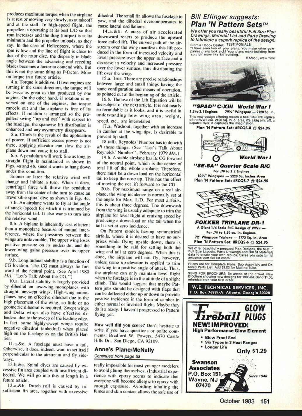
- Lines: .008 x 35-ft steel stranded lines are typical. Fly slowly through level flight, then large loops, then eights, then inverted flight as confidence increases.
- For more maneuverability, lower the pushrod on the control horn one hole or move the CG back incrementally up to about 5/8 in behind the leading edge (test each small change).
- In very calm conditions, longer lines (42 ft) can be fun; otherwise 35–38 ft is a good compromise.
Suggested trimming notes:
- A bit of downthrust and a small geometric dihedral with positive tail incidence produces a stable trainer.
- If the model becomes soft on the lines when the CG is moved rearward, add a small shim (No. 2 washer) under the inside engine-mount screws to introduce a bit of out-thrust.
Using a pressure bladder (tips)
One successful combination:
- A well-broken-in twin-port Cox 290 (new engines can be fussy until run in).
- Bladder made from surgical tubing (e.g., 1/4-in I.D., 1/2-in wall).
- A 5/8 x 3 Top Flite nylon prop (avoid too-small props that require extreme needle settings).
- Cox Super Power fuel or equivalent.
- Add a spring to the needle valve to prevent needle drift.
If you are inexperienced with bladder systems, seek experienced help for filling and needle-valve setup.
For absolute beginners
- For greater durability, substitute 3/16-in wood for the fuselage and 1/8-in for the wing, stab, fin, and spacers.
- Prioritize an engine setup that is easy to restart (Golden Bee or Black Widow with integral tank are convenient).
- If additional weight results from heavier construction, lengthen the nose up to 1/2 in to help balance the model.
Final notes and contact
With reasonable care, the finished plane can weigh about 4 to 4-1/2 oz. Avoid excess glue and heavy finishes. Anne did the decorations and helped brush on the polyurethane; it’s a delightful project for young modelers and their families.
Have fun with your version of Anne’s Plane. Write with questions or comments to: Bradford W. Powers, 5470 Castle Hills Dr., San Diego, CA 92109.
Transcribed from original scans by AI. Minor OCR errors may remain.

