
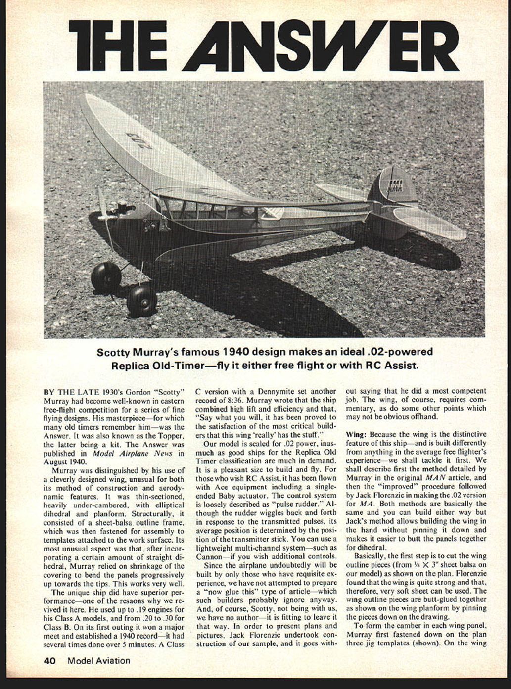
THE ANSWER
BY THE LATE 1930's Gordon "Scotty" Murray had become well-known in eastern free-flight competition for a series of fine flying designs. His masterpiece—for which many old timers remember him—was the Answer. It was also known as the Topper, the latter being a kit. The Answer was published in Model Airplane News in August 1940.
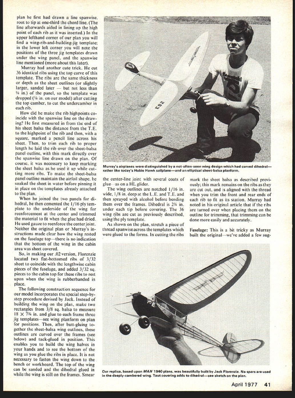
Murray was distinguished by his use of a cleverly designed wing, unusual for both its method of construction and aerodynamic features. It was thin-sectioned, heavily under-cambered, with elliptical dihedral and planform. Structurally, it consisted of a sheet-balsa outline frame, which was then fastened for assembly to templates attached to the work surface. Its most unusual aspect was that, after incorporating a certain amount of straight dihedral, Murray relied on shrinkage of the covering to bend the panels progressively up towards the tips. This works very well.
The unique ship did have superior performance—one of the reasons why we revived it here. He used up to .19 engines for his Class A models, and from .20 to .30 for Class B. On its first outing it won a major meet and established a 1940 record; it had several times done over 5 minutes. A Class C version with a Dennymite set another record of 8:36. Murray wrote that the ship combined high lift and efficiency and that, "Say what you will, it has been proved to the satisfaction of the most critical builders that this wing 'really has the stuff.'"
Our model is scaled for .02 power, inasmuch as good ships for the Replica Old Timer classification are much in demand. It is a pleasant size to build and fly. For those who wish RC Assist, it has been flown with Ace equipment including a single-ended Baby actuator. The control system is loosely described as "pulse rudder." Although the rudder wiggles back and forth in response to the transmitted pulses, its average position is determined by the position of the transmitter stick. You can use a lightweight multi-channel system—such as Cannon—if you wish additional controls.
Since the airplane undoubtedly will be built by only those who have requisite experience, we have not attempted to prepare a "how-to glue this" type of article—which such builders probably ignore anyway. And, of course, Scotty, not being with us, we have no author—it is fitting to leave it that way. In order to present plans and pictures, Jack Florenzie undertook construction of our sample, and it goes without saying that he did a most competent job. The wing, of course, requires commentary, as do some other points which may not be obvious offhand.
Wing: Because the wing is the distinctive feature of this ship—and is built differently from anything in the average free flighter's experience—we shall tackle it first. We shall describe first the method detailed by Murray in the original MAN article, and then the "improved" procedure followed by Jack Florenzie in making the .02 version for MAN. Both methods are basically the same and you can build either way but Jack's method allows building the wing in the hand without pinning it down and makes it easier to butt the panels together for dihedral.
Basically, the first step is to cut the wing outline pieces (from 1/8 × 3" sheet balsa on our model) as shown on the plan. Florenzie found that the wing is quite strong and that, therefore, very soft sheet can be used. The wing outline pieces are butt-glued together as shown on the wing planform by pinning the pieces down on the drawing.
To form the camber in each wing panel, Murray first fastened down on the plan three jig templates (shown). On the wing plan he first had drawn a line spanwise, root to tip at one-third the chord line. (The line afterwards aided in lining up the high point of each rib as it was inserted.) In the upper lefthand corner of our plan you will find a wing-rib-and-building-jig template; in the lower left corner you will note the positions of the three jig templates drawn under the wing panel, and the spanwise line mentioned (more about this later).
Murray had another cute trick. He cut 36 identical ribs using the top curve of his template. The ribs are the same thickness or depth as the sheet outlines (or slightly larger, sanded later — but not less than 1/8 in.) of the panel, so the template was dropped (1/8 in. on our model) after cutting the top camber, to cut the undercamber in each rib.
How did he make the rib highpoints coincide with the spanwise line on the drawing? He first measured in from the end of his sheet balsa the distance from the T.E. to the highpoint of the rib and then, with a square, marked a pencil line across his sheet. Then, to trim each rib to proper length, he laid the rib over the sheet-balsa panel outline, with this mark directly over the spanwise line drawn on the plan. Of course, it was necessary to keep marking the sheet balsa as he used it up while cutting more ribs. To make the sheet-balsa panel outline maintain the airfoil shape, he soaked the sheet in water before pinning it in place on the templates already attached to the plan.
When he joined the two panels for dihedral, he then cemented the 1/16 ply template to the underside of the wing for reenforcement at the center and trimmed the material to fit when the glue had dried. He used gauze to reenforce the center joint. Neither the original plan nor Murray's instructions made clear how the wing rested on the fuselage top — there is no indication that the bottom of the wing in the cabin area was sheet covered.
So, in making our .02 version, Florenzie located two flat-bottomed ribs of 3/32 sheet to coincide with the lengthwise cabin pieces of the fuselage, and added 3/32 sq. pieces to the cabin top for these ribs to rest upon when the wing is rubberbanded in place.
The following construction sequence for our model incorporates the special step-by-step procedure devised by Jack. Instead of building the wing on the plan, make two rectangles from 3/8 sq. balsa to measure 18 x 7-1/4 in. and glue to each frame three jig templates — see wing planform on plan for positions. Then, after butt-gluing together the sheet-balsa wing outlines, these outlines are curved over the frames (see below) and tack-glued in position. This enables you to build the wing halves in your hands and to see the bottom of the wing as you glue the ribs in place. It is not necessary to fasten the wing down to the bench or workboard. The top of the wing can be sanded and the dihedral glued in while the wing is still on the frames. Smear the center-line joint with several coats of glue — as on a HL glider.
The wing outlines are notched 1/16 in. wide, 1/8 in. deep at the L.E. and T.E. and then sprayed with alcohol before bending them over the frames. Dihedral is 2-3/4 in. under each tip before covering. The 36 wing ribs are cut as previously described, using the ply template.
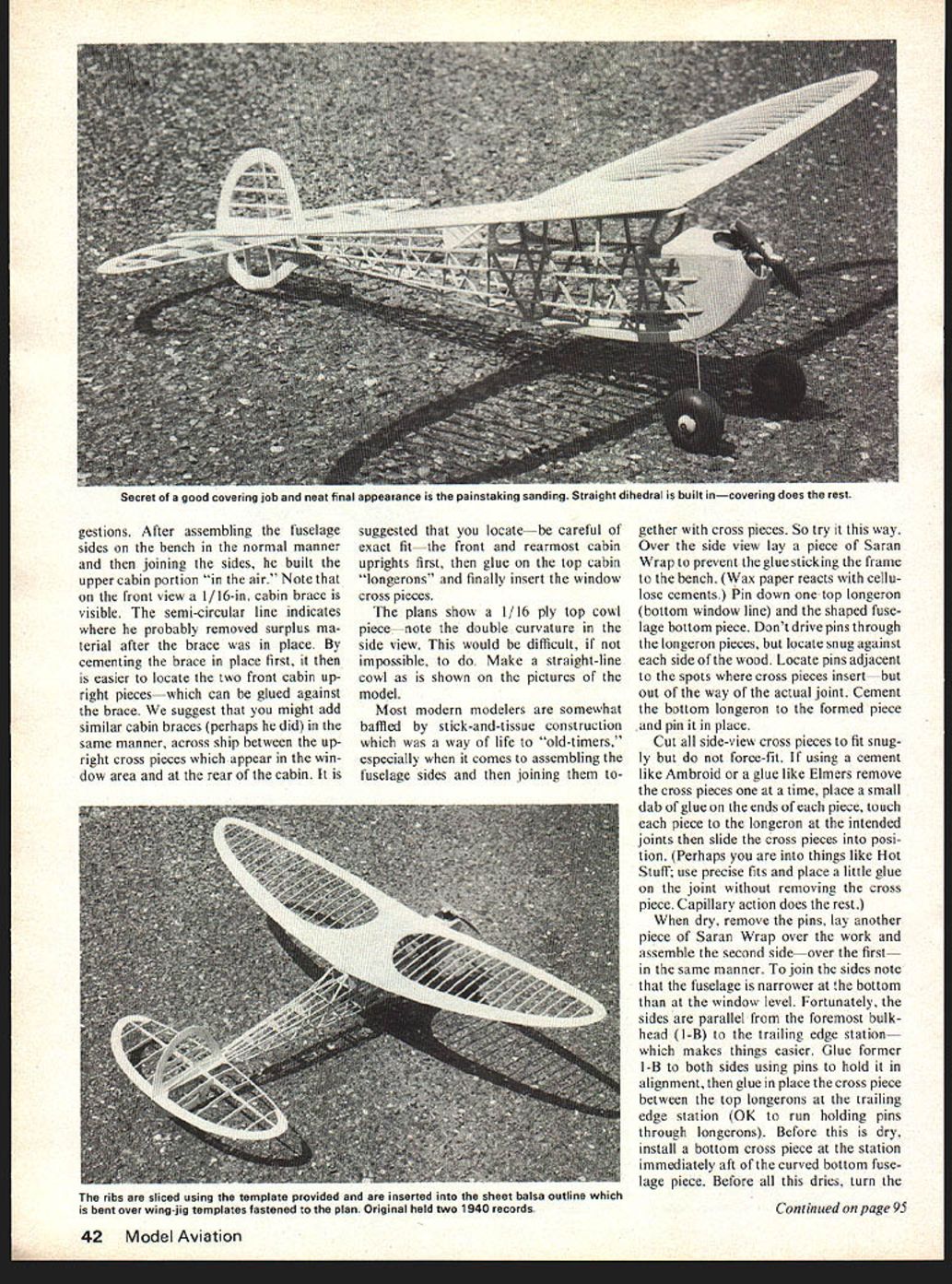
As shown on the plan, stretch a piece of thread spanwise across the templates which were glued to the forms. In cutting the ribs mark the sheet balsa as described previously; this mark remains on the ribs as they are cut out, and is aligned with the thread when you trim the front and rear ends of each rib to fit as its station. Murray had noted in his original article that if the ribs are turned over when placing them on the outline for trimming, that trimming can be done more easily and accurately.
Fuselage:
This is a bit tricky as Murray built the original — we've added a few suggestions — After assembling the fuselage sides on the bench in the normal manner and then joining the sides, he built the upper cabin portion "in the air." Note that on the front view a 1/16-in. cabin brace is visible. The semi-circular line indicates where he probably removed surplus material after the brace was in place. By cementing the brace in place first, it then is easier to locate the two front cabin upright pieces — which can be glued against the brace. We suggest that you might add similar cabin braces (perhaps he did) in the same manner, across ship between the upright cross pieces which appear in the window area and at the rear of the cabin. It is suggested that you locate — be careful of exact fit — the front and rearmost cabin uprights first, then glue on the top cabin "longerons" and finally insert the window cross pieces.
The plans show a 1/16 ply top cowl piece — note the double curvature in the side view. This would be difficult, if not impossible, to do. Make a straight-line cowl as is shown on the pictures of the model.
Most modern modelers are somewhat baffled by stick-and-tissue construction which was a way of life to "old-timers," especially when it comes to assembling the fuselage sides and then joining them together with cross pieces. So try it this way. Over the side view lay a piece of Saran Wrap to prevent the glue sticking the frame to the bench. (Wax paper reacts with cellulose cements.) Pin down one top longeron (bottom window line) and the shaped fuselage bottom piece. Don't drive pins through the longeron pieces, but locate snug against each side of the wood. Locate pins adjacent to the spots where cross pieces insert — but out of the way of the actual joint. Cement the bottom longeron to the formed piece and pin it in place.
Cut all side-view cross pieces to fit snugly but do not force-fit. If using a cement like Ambroid or a glue like Elmers remove the cross pieces one at a time, place a small dab of glue on the ends of each piece, touch each piece to the longeron at the intended joints then slide the cross pieces into position. (Perhaps you are into things like Hot Stuff; use precise fits and place a little glue on the joint without removing the cross piece. Capillary action does the rest.)
When dry, remove the pins, lay another piece of Saran Wrap over the work and assemble the second side — over the first — in the same manner. To join the sides note that the fuselage is narrower at the bottom than at the window level. Fortunately, the sides are parallel from the foremost bulkhead (1-B) to the trailing edge station — which makes things easier. Glue former 1-B to both sides using pins to hold it in alignment, then glue in place the cross piece between the top longerons at the trailing edge station (OK to run holding pins through longerons). Before this is dry, install a bottom cross piece at the station immediately aft of the curved bottom fuselage piece. Before all this dries, turn the
The Answer
Continued from page 43
fuselage upside down on the bench to check its alignment. Weigh it down as much as necessary to hold it true against the surface (put weight on top of longerons nearest bench). Other cross pieces forward of the T.E. station are now inserted. When they are dry the sides are pulled together at the rear and cemented—note the beveled joint there. It is important to do this accurately. To make sure, rest the top of the fuselage on the plan and, if the tail joint is not on the centerline, correct it before the cement dries. The remaining top and bottom cross pieces are now cut to length and glued in place. The upper part of the cabin is tricky, as we said before; some suggestions were given.
Stringers should be hard balsa to prevent unsightly bowing by the shrinkage of the covering.
The nose block pieces should be glued in place before final shaping. Just be sure to true sand the rear and front faces of these pieces before you commit yourself. Start with the side blocks (see comment below on engine installation) which glue to the projecting top longeron and bulkhead 1-B, then glue on the front block, and finally the bottom block. (Note that it is first trimmed to fit and that the inside surface is somewhat cut away for lightness before it is located.)
The engine mounting differs from the original model which had beam mounts. Since the engine is mounted well forward of the front cabin bulkhead, a small plywood firewall is cut out per plans, and is located by means of the two balsa rectangular pieces (grain fore and aft) shown. Blind nuts make it easy to bolt the engine in place, to remove it, or to make thrust-line adjustments by placing thin washers or metal shims between case and firewall—according to your adjustment needs. It would be well to coat the interior of the engine compartment with epoxy to protect it from absorbing fuel and exhaust wastes.
Covering: Important: note that the skeleton photos show a straight dihedral, whereas the finished wing has elliptical dihedral. Doping of the final covering will automatically impart this curvature. If you'd like a specific measurement, each wing half has 2¼ inches dihedral when the panels are first joined together; after the covering shrinks, the tips should each have from 4½ to 4¾ inches dihedral.
It is also important that the covering material be adhered to each rib on both the top and bottom of the wing. Moisten the paper first with a light spray—just enough to make it damp. You will have to stick the covering to the lower sides of the rib anyway in order to retain the camber. By adhering the paper to the top surface, the material will not pull away from the ribs as the tips bow into position.
Covering may be either Japanese tissue or lightweight Silkspan. The former is adequate and perhaps a bit easier to work with, but if you live in an area where punctures are likely Silkspan may be preferred. All balsa surfaces that come into contact with the covering are given two coats of full strength dope, sanding down the fuzz after the first coat. For brushing on coats of dope, thin the dope 50-50. Use only as many coats as needed to fill and stretch the material and, in the case of the wing, enough on its top surface to bow it to its final elliptical shape. Finally, brush on two coats of low-shrink dope—such as Sig. Be sure the covering is filled and taut before applying low-shrink dope because it will not provide further shrinking. If you have any wrinkles at this stage, they will remain.
We'd be interested in how you make out. Do send us some pictures!
When writing to advertisers mention that you read about them in MA.
Transcribed from original scans by AI. Minor OCR errors may remain.

