
Antoinette
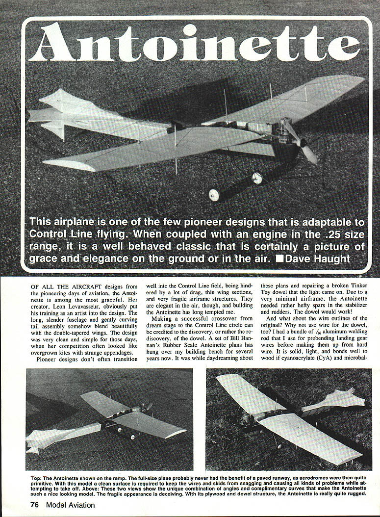
Of all the aircraft designs from the pioneering days of aviation, the Antoinette is among the most graceful. Creator Léon Levavasseur was clearly a design artist — the long, slender fuselage and gently curving tail assembly blend beautifully with the double‑tapered wings. The design is very clean and simple compared with many contemporary pioneers, which often looked like overgrown kites with strange appendages.
Pioneer designs don't often transition well to the Control‑Line field: they are hindered by drag, thin wing sections, and fragile airframe structures. Elegant as they are, though, building an Antoinette has long been tempting. A successful crossover from dream stage to Control Line was made possible by re‑discovering the dowel as a structural member and by using bundled aluminum welding rod where the original used wire. Solid, light joints bond well to wood using cyanoacrylate (CyA) and microballoons.
The full‑size Antoinette probably never benefited from paved runways — aerodromes were primitive. The model needs a clean surface to keep the wire skids from snagging at takeoff. The unique combination of angles and complementary curves make the Antoinette such a pleasing model. Though it looks fragile, with a plywood‑and‑dowel structure the Antoinette is actually quite rugged.
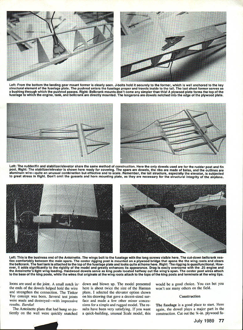
Remember the tail structure — especially the elevator — is subjected to high stress in flight. Do not omit gussets and the horn mounting plate; they are necessary for the airplane's structural integrity.
Construction
Fuselage
- Cut out the 1/8‑in. plywood fuselage plate and position it over the top view on the plans.
- Take a pair of 1/4‑in. dowels and cut them to the length needed for the top longerons. Trim the rear ends of both dowels at an angle so they come together as shown on the plans; glue them together at the rear and to the fuselage plate.
- Cut and install the balsa crossmembers. A 3/32‑in. round file is ideal for making quick, perfect joints.
- When glue has dried, mark and drill the mounting holes in the plywood plate and set the engine in place. Flip the engine over and install blind nuts. Drill the hole for the bellcrank and the slot for the pushrod.
- Pin the fuselage top to the plan upside‑down. Cut out the nose block and carve it to a triangular cross section. Groove the bottom to fit the 1/4‑in. bottom longeron with the round file.
- Make all A formers from 1/8‑in. balsa and one B former from 1/8‑in. plywood. Bend the main landing gear strut from music wire and bolt it to former B with J‑bolts.
- Cut the end‑post dowel to length and glue it to the end of the top longerons, ensuring it stands squarely.
- Glue the nose block to the fuselage plate, locate and glue in the formers, then trim and glue the bottom longeron into the nose block groove and through the formers.
- Add the balsa uprights to the sides, fitting each piece snugly with the file. Add a 1/16‑in. sheet pushrod exit plate and remove the finished fuselage from the building board.
- Install the bellcrank and pushrod. A 3‑in. bellcrank cut down to fit is suitable. The pushrod must pass freely through the fuselage plate and formers. Use the last A former as a pushrod bushing by drilling a 3/32‑in. hole for a close fit that prevents bowing under air loads.
- Bend up the tail‑skid wire and the nose‑skid, brace, and axle wires. Bind and solder where needed and glue them securely at attachment points. Plank the forward fuselage sides and sand smooth.
Tail, Elevator, and Stabilizer
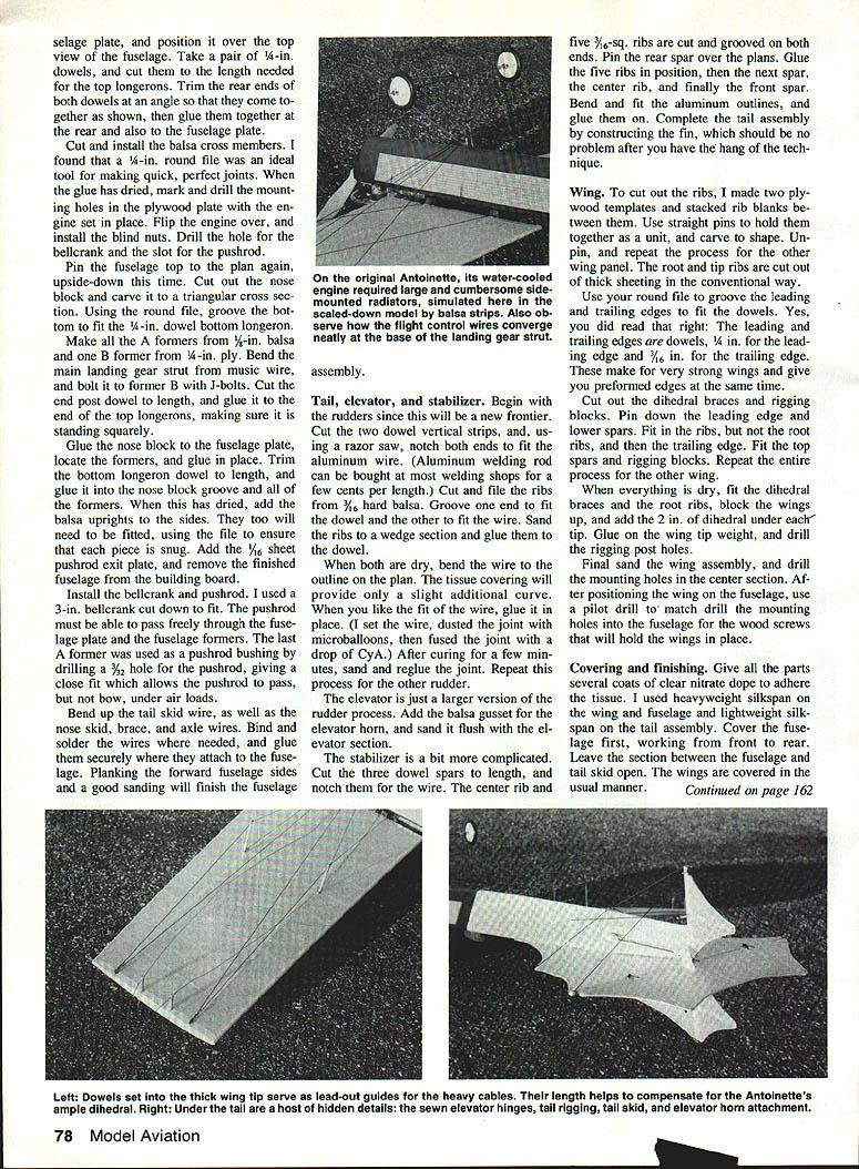
- Rudders:
- Cut two dowel vertical strips and notch both ends with a razor saw to fit the aluminum wire outlines. (Aluminum welding rod can be bought at welding shops.)
- Cut and file the ribs from 3/32‑in. hard balsa. Groove one end to fit the dowel and the other to fit the wire. Sand the ribs to a wedge section and glue them to the dowel.
- When dry, bend the wire outlines to the plan, fit and glue them in place. For strong joints, set the wire, dust the joint with microballoons, apply a drop of CyA, let cure, sand, and reglue as needed. Repeat for the other rudder.
- Elevator:
- Construct as a larger version of the rudder process. Add a balsa gusset for the elevator horn and sand it flush with the elevator section.
- Stabilizer:
- Cut three dowel spars to length and notch them for the wire outline.
- Cut the center rib and five 3/16‑in. square ribs, grooving both ends.
- Pin the rear spar over the plans, glue the five ribs in position, then glue the next spar, the center rib, and finally the front spar.
- Bend and fit the aluminum outline and glue it on.
- Construct the fin using the same technique; fit it to complete the tail assembly.
Important: Reinforce the elevator and horn area; these parts see significant stress in flight.
Wing
- Make two plywood templates and stack rib blanks between them to cut multiple ribs at once. Use straight pins to hold the unit and carve to shape, then unpin and repeat for the other panel.
- Cut the root and tip ribs from 1/8‑in. sheeting in the conventional way. Use the round file to groove the leading and trailing edges to fit the dowels.
- The leading and trailing edges are dowels: use 1/4‑in. dowel for the leading edge and 7/16‑in. dowel for the trailing edge. These give very strong, preformed edges.
- Cut out dihedral braces and rigging blocks. Pin down the leading edge and lower spars, fit in the ribs (but not the root ribs), then fit the trailing edge. Fit the top spars and rigging blocks. Repeat for the other wing.
- When dry, fit the dihedral braces and root ribs, block the wings up, and add about 2 in. of dihedral under each tip. Glue on the wing tip weight and drill the rigging post holes.
- Final‑sand the wing assembly and drill the mounting holes in the center section. Position the wing on the fuselage and use a pilot drill to match‑drill mounting holes into the fuselage for the wood screws that hold the wings in place.
Covering and Finishing
- Give all parts several coats of clear nitrate dope to adhere the tissue.
- Cover the wing and fuselage with heavyweight silkspan; use lightweight silkspan on the tail assembly.
- Cover the fuselage first, working front to rear. Leave the section between the fuselage and tail skid open.
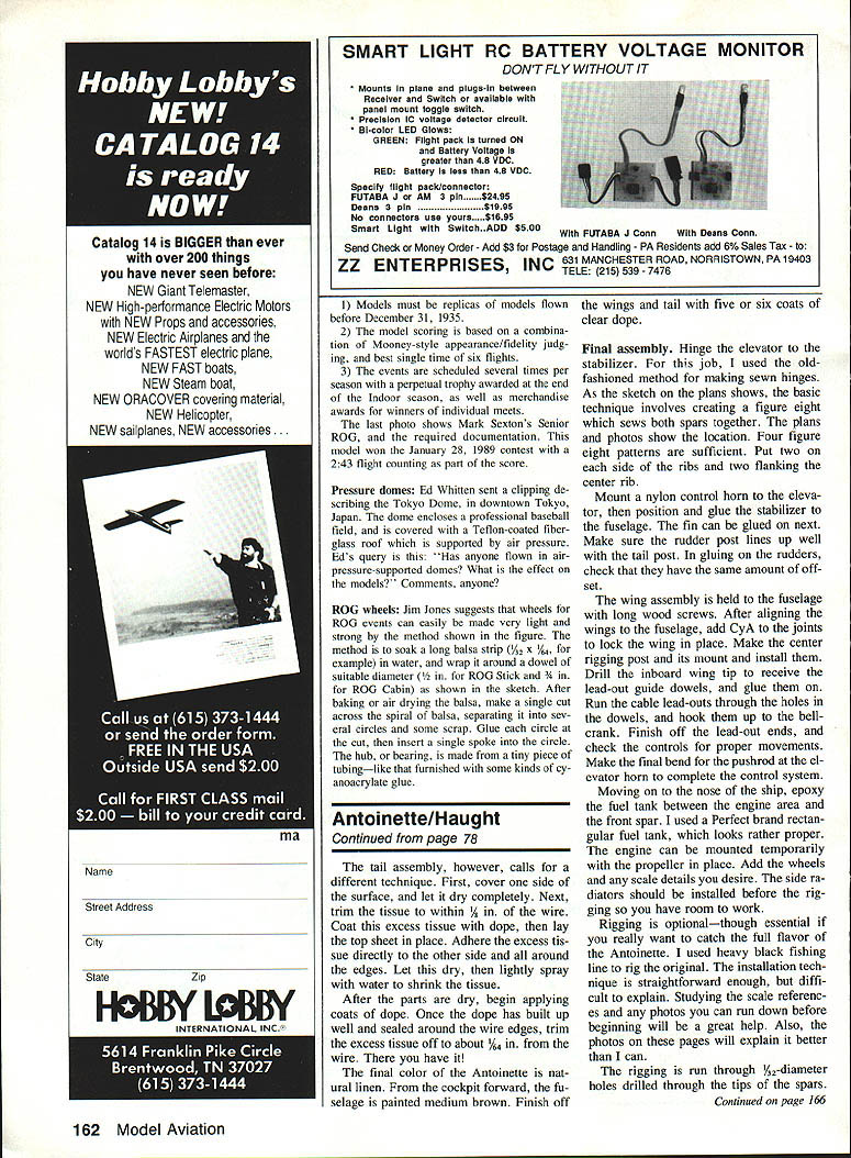
- Tail assembly technique: cover one side, let dry, trim tissue to within 1/8 in. of the wire, coat the excess with dope, lay the top sheet in place, and adhere the excess tissue to the other side and around the edges. Let dry, then lightly spray with water to shrink the tissue. After parts are dry, apply coats of dope. Once dope has built up and sealed around the wire edges, trim the excess tissue to about 1/32 in. from the wire.
- Final color: natural linen for the fabric areas. Paint the fuselage from the cockpit forward medium brown. Finish wings and tail with five or six coats of clear dope.
Final Assembly
- Hinge the elevator to the stabilizer. Old‑fashioned swing hinges work well: sew both spars together with four figure‑eight patterns (two on each side of the ribs and two flanking the center spar).
- Mount a nylon control horn to the elevator, then position and glue the stabilizer to the fuselage. Glue the fin next, ensuring the rudder post lines up with the tail post. When gluing the rudder, check that both rudders have equal offset.
- Attach the wing assembly to the fuselage with long wood screws. After aligning the wings, add CyA to the joints to lock them in place.
- Make and install the center rigging post and mount. Drill the inboard wing tip to receive the lead‑out guide dowels and glue them on. Run the cable lead‑outs through the holes in the dowels and hook them up to the bellcrank. Finish the lead‑out ends and check control movement. Make the final bend for the pushrod at the elevator horn to complete the control system.
- Epoxy the fuel tank between the engine area and the front spar (a rectangular "Perfect" brand tank is suitable). Mount the engine temporarily with the propeller in place. Add wheels and scale details. Install landing gear struts before rigging so you have room to work.
Rigging
- Rigging is optional but essential for authentic appearance. Heavy black fishing line works well.
- Drill 1/32‑in. diameter holes through the tips of the spars at the rigging points indicated on the plans. Thread the line through the holes.
- Slip small lengths of aluminum tubing over the line and crimp to keep the rigging taut and in place.
- Exercise care to avoid introducing warps; undesirable warps can be rigged out.
Balance and Flying
- Check the balance point before flying. It must be within 1/2 in. of the location shown on the plan. Some models may require lead under the engine (example: 2 oz. placed under the engine made one model balance correctly).
- If the center of gravity is too far aft the model will be unstable; moving the CG forward increases stability and makes the model easier to fly. If necessary, unbolt the engine and hollow out the nose block to add lead.
- On takeoff the model will come off the tail skid and rotate; the skid keeps the prop clear of grass until liftoff. In flight the Antoinette is leisurely and graceful. It tolerates moderate winds but avoid strong buffeting.
Materials and Techniques Notes
- Aluminum welding rod (about 1/16‑in.) is useful for prebending landing gear and for wire outlines; it bonds well with CyA and microballoons.
- Use cyanoacrylate (CyA) and microballoons to strengthen wire‑to‑dowel joints where needed.
- A 3/32‑in. round file is very helpful for grooving dowels and fitting parts.
- Reinforce high‑stress areas (elevator horn, tail structure) with gussets and mounting plates.
The Antoinette's fragile appearance is deceiving: with its plywood‑and‑dowel structure and careful construction it becomes a rugged, graceful Control‑Line scale model — a rewarding and unusual choice that won't be common on the flying field.
Transcribed from original scans by AI. Minor OCR errors may remain.

