
ARCSD DEFENDER
D. B. Mathews
Introduction
In the early days of engine-powered Free Flight, the Texas Oil Company donated a trophy to be presented to the winner of a fuel-allotment event held annually at the National Championships.
With the revival of interest in models of the pre-WW II era, the Texaco fuel-allotment event was reborn and has remained a popular Free Flight (and later RC) event in the SAM (Society of Antique Modelers) movement.
The Concept
In 1979 I proposed, in "RC Old-Timers" columns, developing and flying scale designs within the structural and performance parameters of RC-assist Old-Timers, as popularized by SAM. It was felt that it might be fun to build scale designs that would climb on a limited engine run, where they could be thermaled.
My musings at the time leaned toward models with spans of approximately six feet. The idea ultimately became the highly popular 1/2A Scale Texaco event. However, these small .049-powered models are often difficult to see in flight, challenging to build light, and tricky to fly in windy conditions. The event has evolved into a fuel-allotment situation that places more emphasis on maximizing engine runs than true soaring. Despite these limitations, 1/2A Texaco Scale has become extremely popular with both competitive modelers and sport fliers.
To many of us, modeling holds no greater thrill than placing a model in a thermal—whether an RC-assist Old Timer, a Free Flight model, a high-performance sailplane, or a simple hand-launched glider. This combination of a man-made model and a phenomenon of nature is one of the hobby's most enduring attractions. With few exceptions, such as rubber-powered Free Flight and gas-powered Scale, most models flown in thermals bear only a slight resemblance to full-scale aircraft. The exceptions are the 1/2A Scale Texaco models.
Wouldn't it be neat to park an easily seen, good-looking scale model in a thermal and watch it majestically climb with power off, as if driven by some unseen force, and then end the flight by landing the model at your feet? That is what this design is all about.
The Model
This design should not be confused with the sport Defender published in the April 1995 Model Aviation. While the outlines and dimensions are the same, this version has been designed for maximum lightness to maximize its ability to thermal.
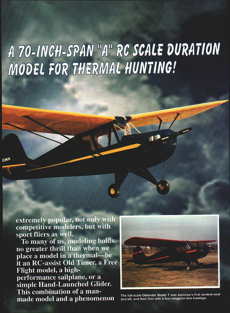
This version of the Aeronca Defender (Model T) was designed using lessons learned while converting a number of Old-Timer (pre-1942) Free Flight designs to two- and three-channel RC. Many Old-Timers are thrilling but not particularly realistic in appearance. This design combines the best aspects of an Old-Timer with scale looks, in an easily seen and constructed size.
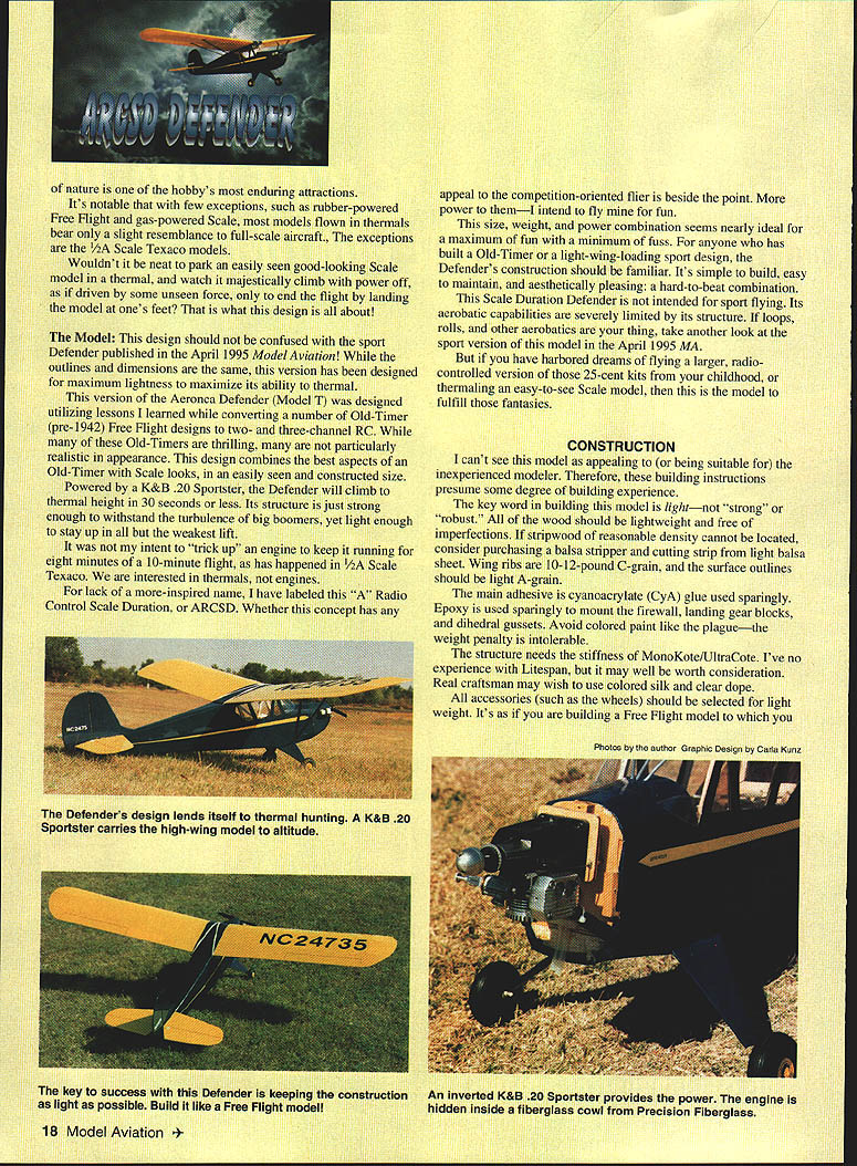
Powered by a K&B .20 Sportster, the Defender will climb to thermal height in 30 seconds or less. Its structure is just strong enough to withstand turbulence from big thermals, yet light enough to stay up in all but the weakest lift.
It was not my intent to "trick up" an engine to keep it running for eight minutes of a 10-minute flight, as has happened in 1/2A Scale Texaco. We are interested in thermals, not engines.
For lack of a more inspired name, I have labeled this "A" Radio Control Scale Duration, or ARCSD. Whether this concept appeals to the competition-oriented flier is beside the point—more power to them. I intend to fly mine for fun.
This size, weight, and power combination seems nearly ideal for maximum fun with minimum fuss. For anyone who has built an Old-Timer or a light-wing-loading sport design, the Defender's construction should be familiar. It's simple to build, easy to maintain, and aesthetically pleasing.
This Scale Duration Defender is not intended for sport flying. Its aerobatic capabilities are severely limited by its structure. If loops, rolls, and other aerobatics are your thing, consider the sport version of this model (see April 1995 Model Aviation). But if you have harbored dreams of flying a larger, radio-controlled version of those 25-cent kits from your childhood, or thermalling an easy-to-see scale model, this is the model to fulfill those fantasies.
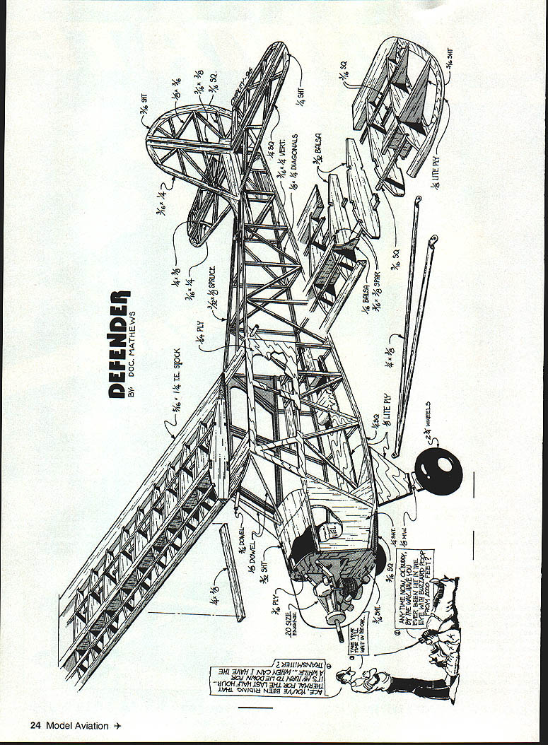
Construction
These instructions presume some building experience. The key word in building this model is light — not "strong" or "robust." Use lightweight, defect-free wood. If reasonable-density stripwood cannot be located, consider purchasing a balsa stripper and cutting strip from light balsa sheet. Wing ribs are 10–12 lb C-grain; surface outlines should be light A-grain.
- Main adhesive: cyanoacrylate (CyA); use sparingly.
- Epoxy: use sparingly to mount firewall, landing gear blocks, and dihedral gussets.
- Avoid colored paint — the weight penalty is intolerable.
- Covering: the structure needs the stiffness of MonoKote or UltraCote. Litespan may be worth consideration. Real craftsmen may prefer colored silk and clear dope.
- Accessories: select for light weight (wheels, fittings, etc.).
Suggested radio and power components:
- Three one-ounce servos
- 125-mAh battery pack (consider a 270-mAh pack for longer flights)
- 1.3-ounce receiver
You should be able to approach a 10 ounces-per-square-foot wing-loading goal; another ounce won't hurt. I once sat absorbed watching the Defender float around; flights past 20 minutes have happened on a charge from a 270-mAh pack.
Torque-rod landing gear and shock-mounted fairings are light and effective. Keep spare music wire available — once bent, it's difficult to unbend. Music wire and fiberglass cowlings are available from Precision Fiberglass, 2805 Big Bend Dr., Maryville, TN 37801; tel. (800) 753-8469.
The cowling requires a light coat of filler followed by two spray coats of color-matched covering. Dummy cylinders are cut from a block of balsa. Use double-sided tape to hold sandpaper on the cowling and rub the dummies against it to create a neat joint. Dowel sections are used to nail the cylinders to the cowling; use epoxy. Other details are made from balsa scraps.
The inverted engine has not presented starting problems when an electric starter is used. Tank plumbing should place a vent on both top and bottom for easy filling and emptying.
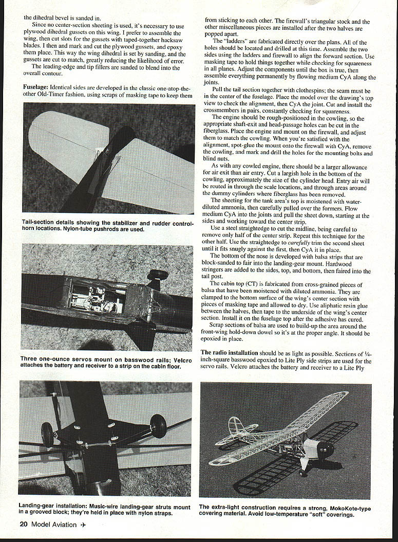
Tail Feathers
- Develop outline pieces using carbon paper to transfer the drawing to balsa, then jigsaw the outline.
- Do not separate elevator halves until the wire joiner has been installed.
- Shape hinged surfaces by block-sanding; sand outer surfaces to resemble full-scale tubing.
- Install hinges after covering is complete.
Wing
- Make a wing-rib master pattern using carbon paper and cut ribs from stacks of light C-grain sheet.
- Obtain final contour by jigsawing, carving, and block-sanding. Cut spar notches as accurately as possible.
- Build wing panels over the drawing from the bottom up. Use precut balsa web strips to position ribs.
- Cut bottom spars flush with tip rib, then position tips. Use scrap-balsa spar extensions to reinforce tips.
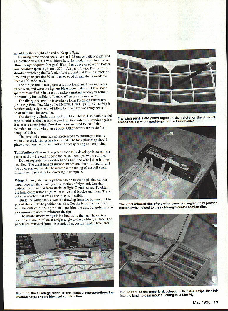
- The most-inboard wing rib is tilted using a jig; center-section ribs are installed at a right angle to the building surface.
- Remove panels, sand edges true, glue panels together, then cut slots for dihedral braces with taped-together tapered-tooth hacksaw blades.
- Because no center-section sheeting is used, use plywood dihedral gussets. I prefer to assemble the wing, then cut gusset slots to match the set dihedral. Epoxy the gussets in place.
- Sand leading-edge and tip fillers to blend into the overall contour.
Fuselage
- Develop identical sides in the classic Old-Timer one-atop-the-other fashion, using masking tape to keep them from sticking together.
- Install firewall triangular stock and miscellaneous pieces after separating the halves.
- Fabricate the "ladders" directly over the plans and drill all holes at this time.
- Assemble the two sides using ladders and firewall to align the forward section. Use masking tape to hold while checking squareness; adjust until box is true and then flow medium CyA along joints to permanently assemble.
- Pull the tail section together with clothespins; the seam must be centered. Place model over top-view drawing to check alignment before CyAing the joint.
- Cut and install crossmembers in pairs, constantly checking for squareness.
Engine and cowling:
- Rough-position the engine in the cowling so appropriate shaft-exit and head-passage holes can be cut in the fiberglass.
- Place engine and mount on firewall and adjust to match cowling. Spot-glue the mount to the firewall with CyA, remove cowling, then mark and drill holes for mounting bolts and blind nuts.
- Allow more air exit than entry: cut a largish hole in the bottom of the cowling approximately the size of the cylinder head. Air is routed in through scale locations and around dummy cylinders where fiberglass has been removed.
- The sheeting for the tank area's top is moistened with water-diluted ammonia, then carefully pulled over the formers. Flow medium CyA into joints and pull the sheet down from sides toward the center strip.
- Use a steel straightedge to cut the midline, removing only half the center strip; repeat for the other half and trim until the two pieces fit snugly, then CyA in place.
- Develop the bottom of the nose with balsa strips block-sanded to fair into the landing-gear mount. Add hardwood stringers to sides, top, and bottom, then fair into the tail post.
Cabin top and hold-down:
- Fabricate the cabin top (CT) from cross-grained balsa moistened with diluted ammonia. Clamp to the underside of the wing center section with masking tape and allow to dry.
- Use aliphatic resin glue between halves, then tape to the wing's underside until cured. Install on the fuselage top after adhesive cures.
- Build up the area around the front-wing hold-down dowel with scrap balsa to set the proper angle and epoxy in place.
Radio installation:
- Keep radio installation as light as possible.
- Use 1/4-inch-square basswood rails epoxied to Lite Ply side strips for servo rails.
- Velcro the battery and receiver to a Lite Ply strip on the cabin floor.
- Recommended components: three one-ounce servos, 125-mAh battery pack (consider upgrading to 270-mAh), and a 1.3-ounce receiver.
Landing gear:
- Torque-rod landing gear with shock-mounted fairings works well and is light. Use the lightest ideas you can devise and have spare wire available.
Precision Fiberglass cowling:
- Fiberglass cowling available from Precision Fiberglass requires a light coat of filler, two spray coats to color match covering, and dummy cylinders made from balsa. Use dowel sections and epoxy to attach cylinders and finish other details similarly.
Windows and Controls
- Use flexible nylon-tube pushrods for rudder and elevator; use a cable for the throttle. Roughen pushrods at anti-flex brace and tail-exit locations for better adhesion.
- 1/4-inch plywood window frames are larger than underlying framework to create a "sill" for clear plastic. Adhere plastic with RC/5-6 applied with a glue gun after fuselage covering is complete.
- Side windows: score and break the plastic at proper outline. Trim windscreen to fit.
- Make the front hold-down dowel hole with a paper punch. Install windscreen by cutting away a narrow strip of covering from the bottom border, slipping the plastic into the sill, and adhering with RC/5-6. Use masking tape until glue dries. Dress raw edges with trim tape.
Struts
- Assemble struts over the drawings. They are non-functional and can be kept very light.
- Cut slots for nylon straps, sand the struts to an airfoil, and position with the wing banded to the fuselage. Affix straps with CyA.
- Attach struts with #2 sheetmetal screws into small hard points in the wing and along the bottom longerons of the fuselage.
Finish
- Do not use low-temperature "soft" covering materials. Give all exposed wood and fiberglass parts one very light, well-sanded coat of filler (K&B or similar). Lightly spray matching colors.
- Aeronca logo and "N" numbers are available in high-quality vinyl from JO Designs (Rt. 1, Box 225AA, Stratford, OK 74672).
Flying
- Take off with half throttle (or less), then advance power once the model is safely airborne. With full power at the ground, the model accelerates rapidly and may jump into the air unexpectedly. The Defender could also be hand-launched.
- Rate of climb is a function of engine rpm. A fairly open left-hand climbing turn is more controlled; a straight-up climb can roll the model onto its back.
- Shut off power before the model gets too small to see and enjoy thermal hunting.
- I strongly recommend Dave Thornburg's Old Buzzard's Soaring Book for anyone interested in locating thermals.
- The Defender indicates lift when its wings rock and its turn tightens. Keep turns relatively open to avoid spiral-dive tendencies; once in lift the model will largely take care of itself.
- Avoid getting too high and too far downwind. If visibility becomes a problem, fly upwind parallel to the field and look for another thermal.
- With such a light wing loading, dead-stick landings are easy. Line up with the field and do S-turns to burn off altitude; with practice the model can be landed at your feet.
Build a Defender and join in the fun—you will enjoy it!
D.B. Mathews 909 N. Maize Rd. Townhouse 734 Wichita, KS 67212
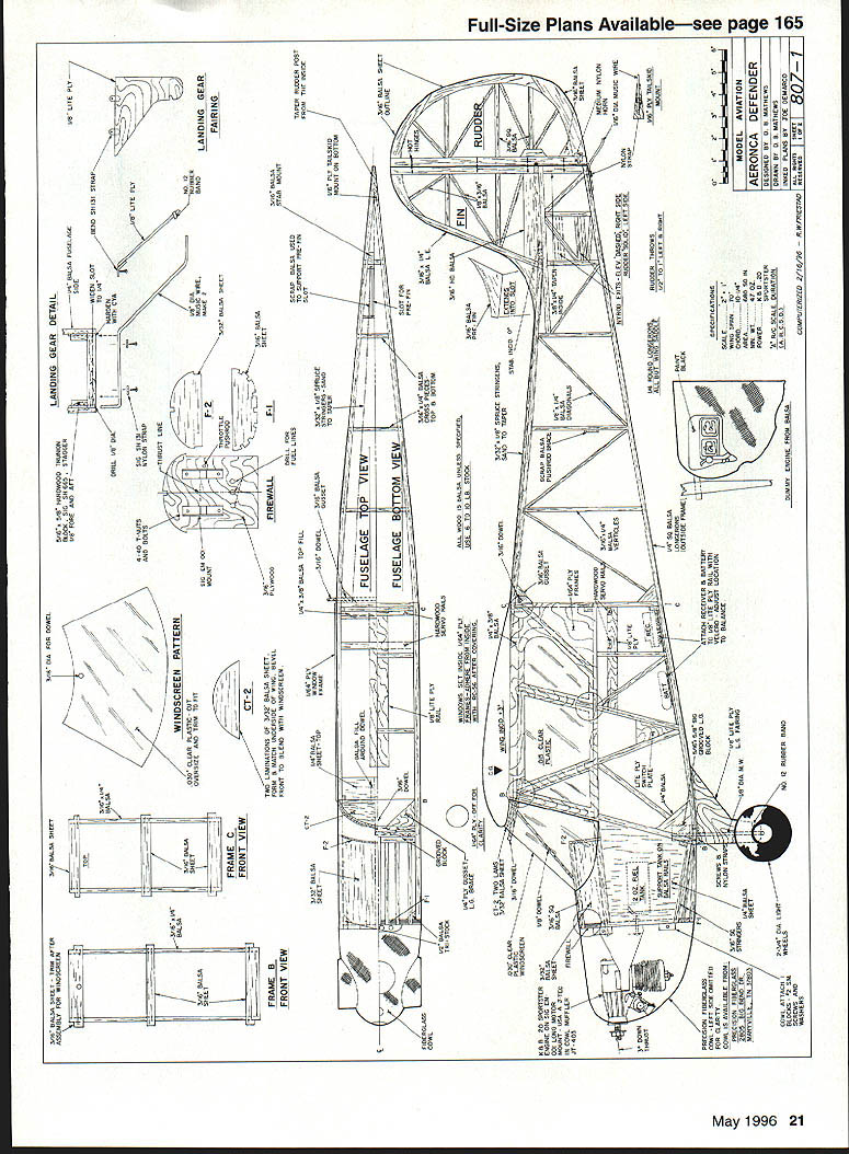
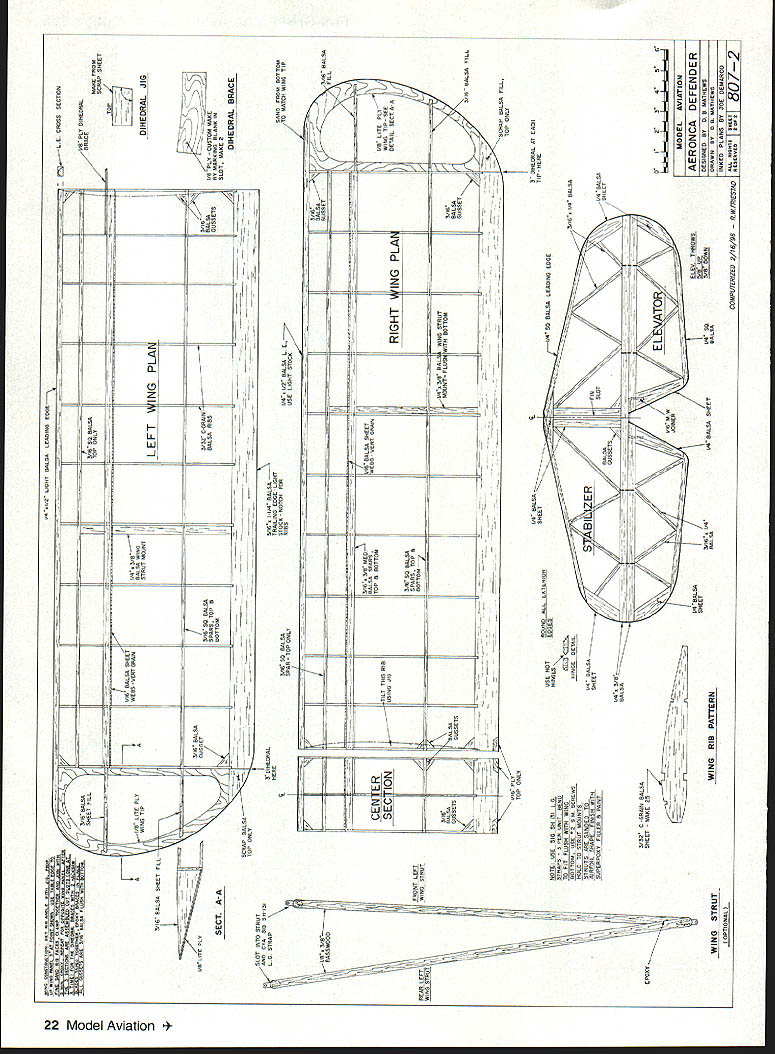
Plans and Diagrams
(Model: Aeronca Defender — Plan No. 807–2 — compiled from original plans)
- Fuselage top view
- Fuselage bottom view
- Rudder
- Fin
- Firewall
- Landing gear detail
- Windscreen pattern
- Frame C — front view
- Frame E — front view
- Frame F — front view
- Left wing plan
- Right wing plan
- Center section
- Section A‑A
- Dihedral jig
- Dihedral brace
- Wing strut
- Wing rib pattern
- Stabilizer
- Elevator
- Landing gear detail (duplicate detail)
- Wing tip
(Note: full-size drawings and detail labels shown on the plan sheet)
Transcribed from original scans by AI. Minor OCR errors may remain.

