
Argosy I
Standing on the ramp at Chicago's O'Hare Airport, deafened by the roar of the big jets, it's not easy to picture how it must have been 50 years earlier. Turn the calendars back half a century and the scene requires a real effort of imagination. Yet the image comes alive: cracks in the paving, the smell of oil, blasts of wind, steel fences blurring into grassy fields, and mountains of parked cars becoming nearby hills of spring wheat. Wherever there are wings, engines, and dreams, the ghosts of yesterday's wings are never far away.
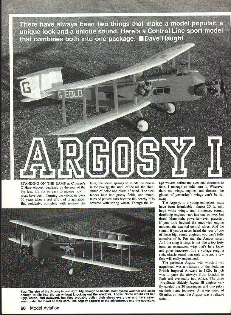
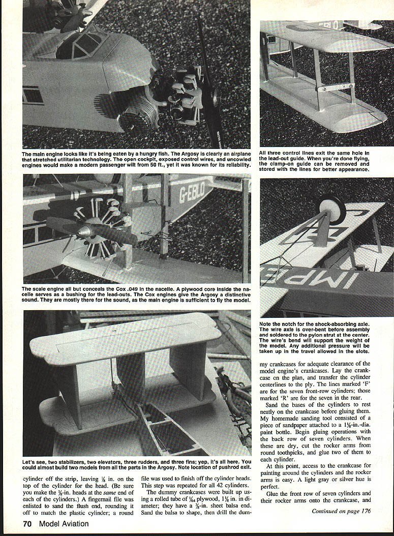
To a young enthusiast the Argosy must have been formidable: almost 20 ft. tall, huge white wings, and immense, round, throbbing engines — not one or two, but three. Mammoth, powerful, and even graceful if you look beyond the uncowled engine mounts and external control wires. The sound of those big round engines is unique; for me, the Argosy sings. Its vintage song is rich and enduring, appreciated by time and a few devoted fans.
The particular Argosy I knew was a mainstay of the fledgling Imperial Airways in 1926. Its job was to pave the airways from London to Paris and eventually into Africa. The three 14-cylinder Siddeley Jaguar IIL engines easily carried 20 passengers and two pilots on their journeys. At a top speed of about 90 mph, the Argosy was a reliable steed.
Though soon outstripped by faster aircraft, the Argosy lives on in scale models. A well-built scale model can capture the ship's feel around a grass field, surrounded by head-high corn and cheered by enthusiastic friends. The thrill is the same remembered thrill; adding the second and third engines squares and then cubes the excitement — and the sound.
If you're itching to get to the balsa, read on. Otherwise, check your pulse.
Construction
Biplanes are tough to build; when the bug hits you, you're in for it. The Argosy is tougher still. Building two wings is a lot, but the Argosy also requires two stabilizers, three rudders, two nacelles, and substantial rigging. This is not a model you put together over a long weekend — it's a serious project, but very well worth the effort.
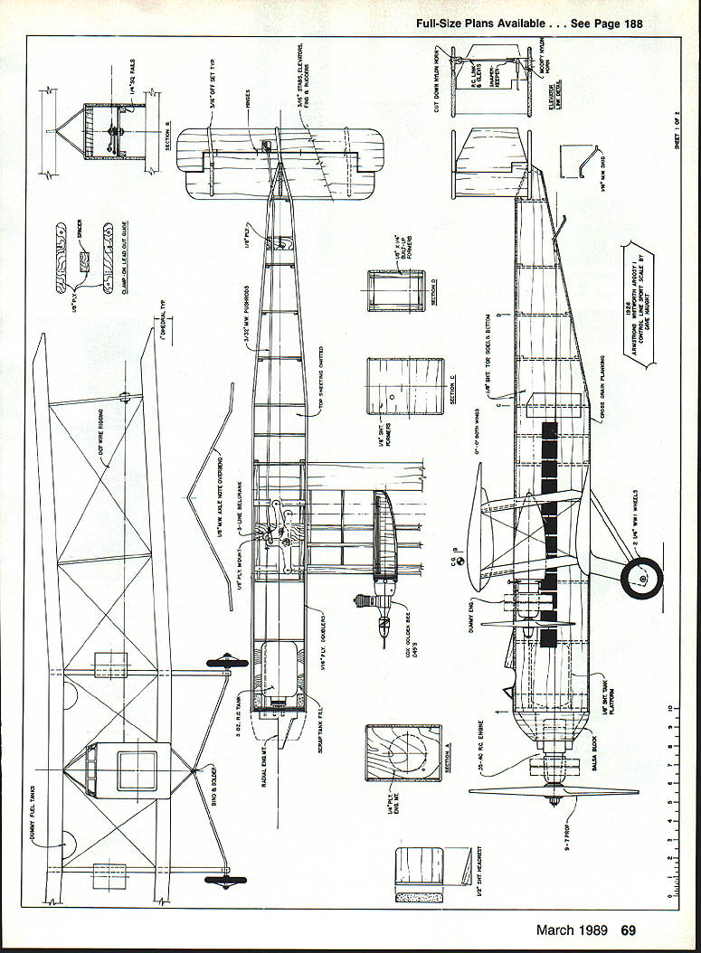
- Study the plans until you can draw them from memory.
- Find Kenneth Munson's Airliners 1919–Present Day for a detailed two-view drawing of the Argosy; it answers many questions.
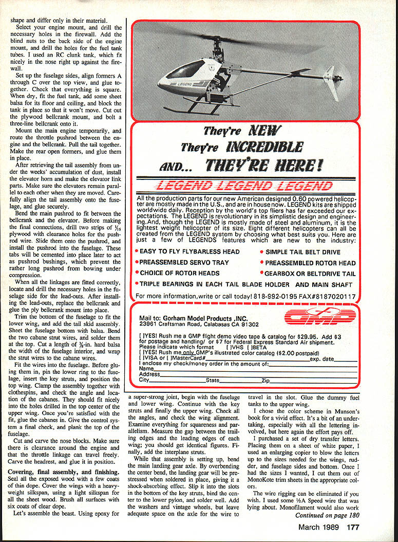
Tail assembly
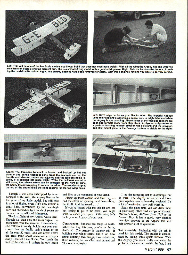
Begin with the tail to gain early encouragement. The Argosy model does not typically have excess tail weight; in some builds you may even need to add a few ounces to the tail to achieve proper balance because of the long moment arm provided by the twin stabilizers.
- Cut parts from medium-weight 3/16-in. balsa.
- You will need two stabilizer/elevator parts and three rudder/fin pieces.
- Sand edges appropriately.
- Install hinges on stabilizers and elevators before final assembly.
- Mark fin locations top and bottom and glue rudders/fins offset as shown on the plan.
- Glue the fins to the bottom stabilizer, check straightness and parallelism, then add the upper stabilizer and reglue joints as needed.
Scale model (tail and small parts)
- Equip stabilizers and elevators with your preferred hinges.
- Mark fin locations on the top and bottom before gluing.
- Glue rudders and fins together and fit to the tail.
- Any missed sanding can be touched up once major joints are dry.
Wing
Each wing is built in three panels as shown on the plans. The lower wing is intentionally a bit longer than the upper wing.
- Cut out all ribs, tips, and dihedral braces; notch trailing edges.
- Pin lower spars, leading and trailing edges to the workbench and position ribs with correct spacing.
- Note: interplane struts are 5/16 in. thick; key struts are 1/4 in. thick.
- After ribs dry, add top spars and join tip panels to center sections with dihedral angles.
- Drill the upper wing center rib R-1 at the indicated angle for the cabane struts.
- Attach the landing gear plate to the lower wing center section.
- Reglue main joints, add gussets as needed, carve and sand leading edges, add tip weight, and solder the wire landing gear pylon to the lower wing.
Key and interplane struts
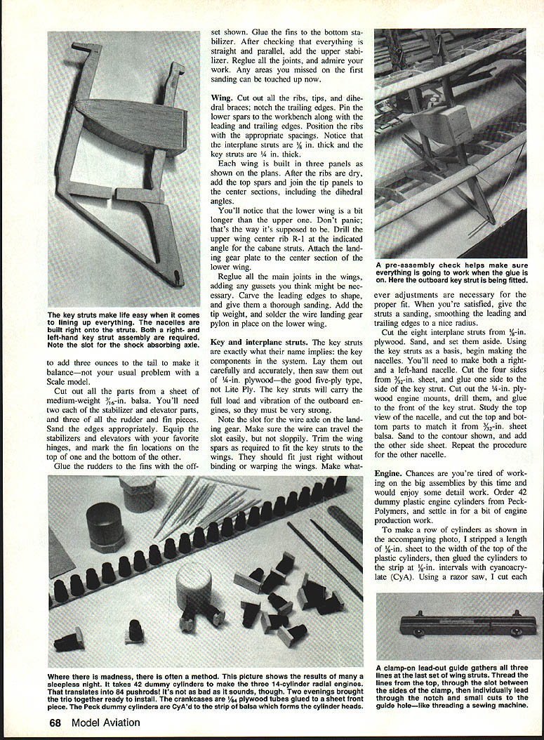
The key struts carry significant load and vibration from the outboard engines and must be strong.
- Saw key struts from 1/4-in. plywood (good five-ply, not Lite Ply).
- Include slot for the wire axle on the landing gear; ensure the wire travels the slot freely but not sloppily.
- Trim wing spars as required so key struts fit without binding or warping.
- Sand and round leading and trailing edges of the struts.
- Cut eight interplane struts from 1/8-in. plywood; sand and set aside.
Nacelles (right- and left-hand)
- Use key struts as a structural base.
- Cut four nacelle side pieces from 3/32-in. sheet and glue one side to the key strut.
- Cut 1/8-in. plywood engine mounts, drill, and glue to front of key strut.
- Cut top and bottom nacelle parts from 3/32-in. balsa to match top view, sand to contour, and add the other side sheet.
- Repeat for the other nacelle.
Engine (dummy engines)
Detail work is rewarding after big assemblies.
- Order 42 dummy plastic engine cylinders (e.g., from Peck-Polymers).
- Strip a length of 1/8-in. sheet to the width of the cylinder tops and glue cylinders at 1/8-in. intervals with cyanoacrylate (CyA).
- Use a razor saw to cut each cylinder off the strip, sand bases level, and fill gaps with a tiny drop of CyA.
- Cut each cylinder so there is 1/8-in. on the top for the head; make sure the head orientation is consistent.
- Sand and round the heads to match the plastic cylinder profile.
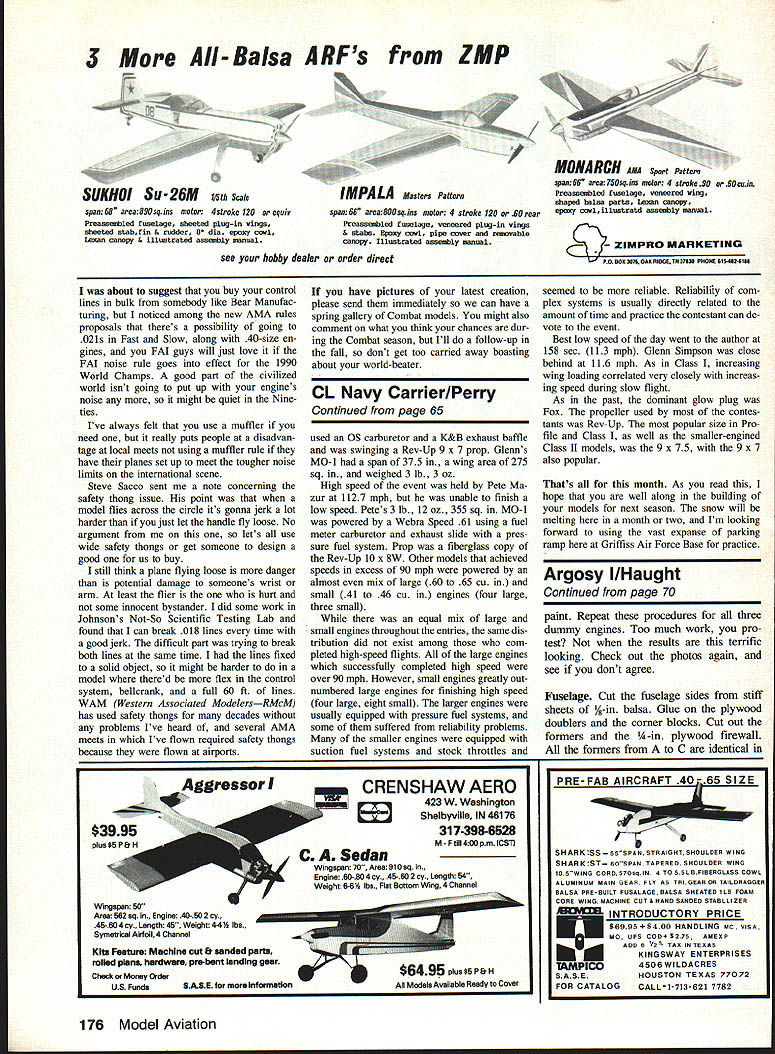
- Build dummy crankcases using a rolled tube of 1/64-in. plywood (approx. 1/16-in. dia.) with a 3/32-in. balsa end; sand and drill for clearance to the model engine's crankcase.
- Transfer cylinder centerlines from plan to ply. Mark "F" for front-row and "R" for rear-row positions.
- Sand cylinder bases to sit neatly on the crankcase, then glue the back row of seven cylinders first.
- Cut rocker arms from round toothpicks and glue two per cylinder.
- Paint crankcase and cylinders in a light gray or silver before fitting the front row.
- Repeat for all three dummy engines, finishing nacelles by cementing dummy engines and exhausts in place.
Fuselage
- Cut fuselage sides from stiff 1/8-in. balsa sheet.
- Glue on plywood doublers and the nose block.
- Cut formers and a 1/8-in. plywood firewall. Formers A–C are identical.
- Assemble the fuselage box, gluing formers, installing top and bottom longerons.
- Add 1/16-in. top decking and bottom sheeting per plans.
- Epoxy the tail skid mount plate to the fuselage bottom and install the pushrod bellcrank.
- Set up fuselage sides, align formers A–C over the top view, and glue together squarely.
- Fit fuel tank (an RC clunk tank works well) in the nose against the firewall; add sheet balsa for tank floor/ceiling and block it in place.
- Cut plywood bellcrank mount and bolt a three-line bellcrank onto it.
- Mount main engine temporarily and route throttle pushrod between engine and bellcrank.
- Make rear formers and glue in place, install elevator horn and linkages while ensuring elevators remain parallel.
- Bend main pushrod to fit between bellcrank and elevator. Drill two strips of 3/16-in. plywood with clearance holes for the pushrod wire, slide them onto the pushrod, and install as bushings to prevent bowing.
- Locate and drill holes in the fuselage sides for lead-outs, install lead-outs, replace bellcrank, and glue ply bellcrank mount in place.
- Trim fuselage bottom to fit the lower wing and add tail skid assembly; sheet the fuselage bottom with balsa.
- Bend cabane strut wires, solder them at the top, and wrap/attach to a 3/8-in. hard balsa strip to hold spacing.
Cabane and interplane struts
- Cut cabane and interplane struts from hardwood and fit to fuselage and wings.
- Use heavy thread wrapping to secure wires to the wooden strip on top struts to hold correct spacing for the top wing.
- Pin lower ring to fuselage, insert key struts, position top wing, clamp with clothespins, and check angle/location of cabanes.
- Fit cabanes into holes drilled in the top center of the upper wing and glue when satisfied.
- Add interplane struts after checking all alignments.
Balance
- Add three ounces to the tail if needed to achieve balance — not usually required, but common on some builds.
- With the wing arrangement and the Argosy's long moment arm from twin stabilizers, the model generally flies smoothly without excessive nose weight.
Final assembly
- Cement nacelles and dummy engines in place, finish cowlings and detail work.
- Install radio gear or control-line hardware as required.
- Check control throws and balance before maiden flight.
- Seal all exposed wood with a few coats of thin dope.
- Cover wings with heavyweight silkspan and sheet wood surfaces with light silkspan; brush all surfaces with six coats of clear dope.
Assembly sequence and landing gear
- Using epoxy for strong joints, begin by epoxying the fuselage to the lower wing, then add key struts and finally the upper wing.
- Check angles, wing alignment, squareness, and parallelism. Measure gaps between trailing and leading edges of each wing to ensure identical figures.
- Bend the main landing gear axle; overbend the center so the axle is pre-stressed when soldered for shock-absorbing effect.
- Slip axle into slots in bottom of key struts, cement to lower pylon, and solder well. Add washers and vintage wheels, leaving space for wire travel in the slot.
- Glue dummy fuel tanks to the upper wing.
Painting and markings
- A vivid color scheme from Munson's book works well. Lettering can be made with dry transfer letters enlarged on a copier and cut from MonoKote trim sheets for the desired colors.
- Wire rigging is optional; 1/2A speed wire or monofilament both work.
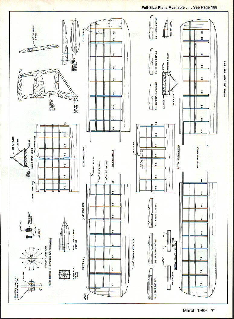
Rigging and lead-outs
- The basic rigging pattern is shown on the plans. Lead-outs should extend a few inches beyond the nacelles for a cleaner look.
- Make a lead-out guide from two plywood strips glued together with a spacer between. The line hole is identical on both strips but the slots leading to the holes differ: on the front strip the slot exits at the bottom; on the back strip it exits at the top.
- Clamp the lead-out guide to the wing strut so the line hole is about 1/4 in. above the lower wing.
- Slip each flying line individually between the strips in the spacer gap from the bottom side, then feed the wire through the slots into the hole from front and back. Repeat for all three lines.
- The guide clamps on only for flying; you may elect to glue it in place for simplicity.
Engines and flying
- Add engines and check thrust angles of each.
- Recommended power setup:
- Outer engines: reliable Cox .049s — easy to start and manage.
- Main engine: K&B .40 RC — ample power to fly the Argosy on its own.
- Preparation and starting sequence:
- Remove dummy engines if desired before fueling.
- Warm up and top off tanks.
- Start engines in sequence: outboard engine, inboard outer engine, then carefully the main engine.
- Refill the running .049s before takeoff using a long extension filler of plastic tubing.
- Flying: the Argosy will take off with all three engines at low throttle. Increase the main throttle for touch-and-goes and in windy conditions.
- Safety note: triples are more fun but take care during starting and ground handling.
One thing's certain: flying a piece of aviation history is easier than reconstructing it in your imagination. Having approached the Argosy both as an original and as a model, I can vouch for its magic. Enjoy your piece of 1926.
Transcribed from original scans by AI. Minor OCR errors may remain.

