
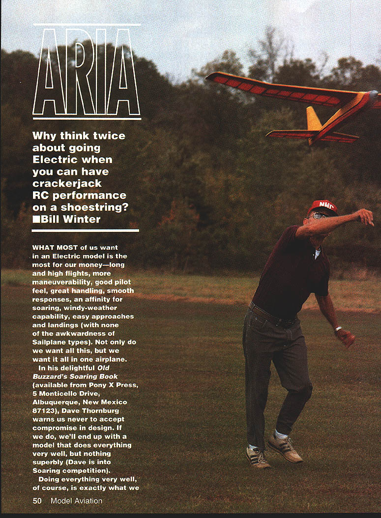
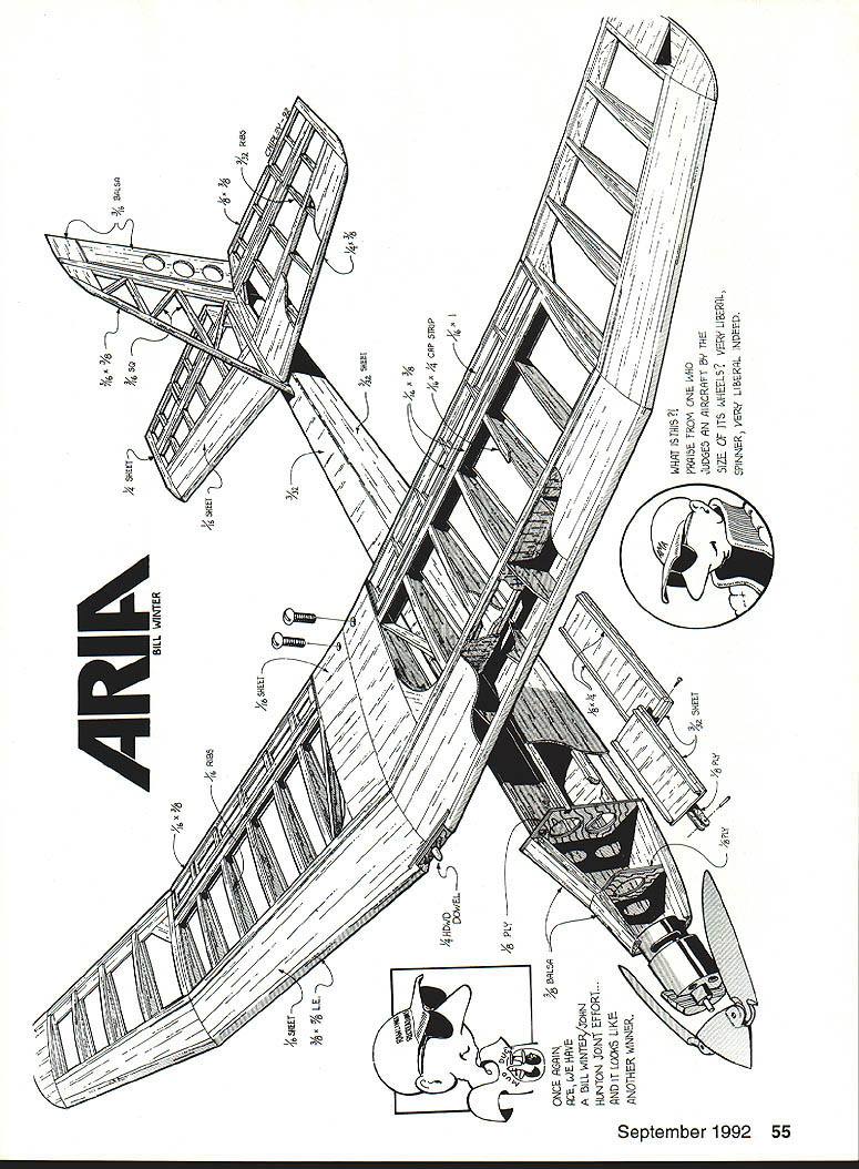
ARIA
Bill Winter
Why think twice about going electric when you can have crackerjack RC performance on a shoestring?
What most of us want in an electric model is the most for our money—long, high flights; good maneuverability; a great pilot feel; smooth responses; an affinity for soaring; windy-weather capability; easy approaches and landings (without the awkwardness of sailplane types). Not only do we want all this, but we want it all in one airplane.
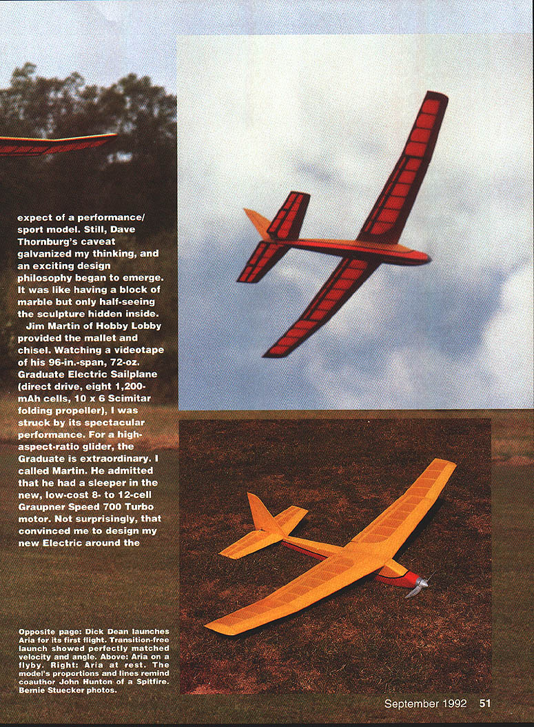
In his delightful Old Buzzard's Soaring Book (available from Pony X Press), Dave Thornburg warns us never to accept compromise in design. If we do, we'll end up with a model that does everything very well, but nothing superbly. Doing everything very well, of course, is exactly what we expect of a performance/sport model. Still, Thornburg's caveat galvanized my thinking, and an exciting design philosophy began to emerge.
Jim Martin of Hobby Lobby provided the impetus. Watching a videotape of his 96-in. span, 72-oz. Graduate electric sailplane (direct drive, eight 1,200-mAh cells, 10 x 6 Scimitar folding propeller), I was struck by its spectacular performance. For a high-aspect-ratio glider, the Graduate is extraordinary. Martin admitted he had a sleeper in the new, low-cost 8- to 12-cell Graupner Speed 700 Turbo motor. That convinced me to design Aria around the Graupner Speed 700 Turbo.
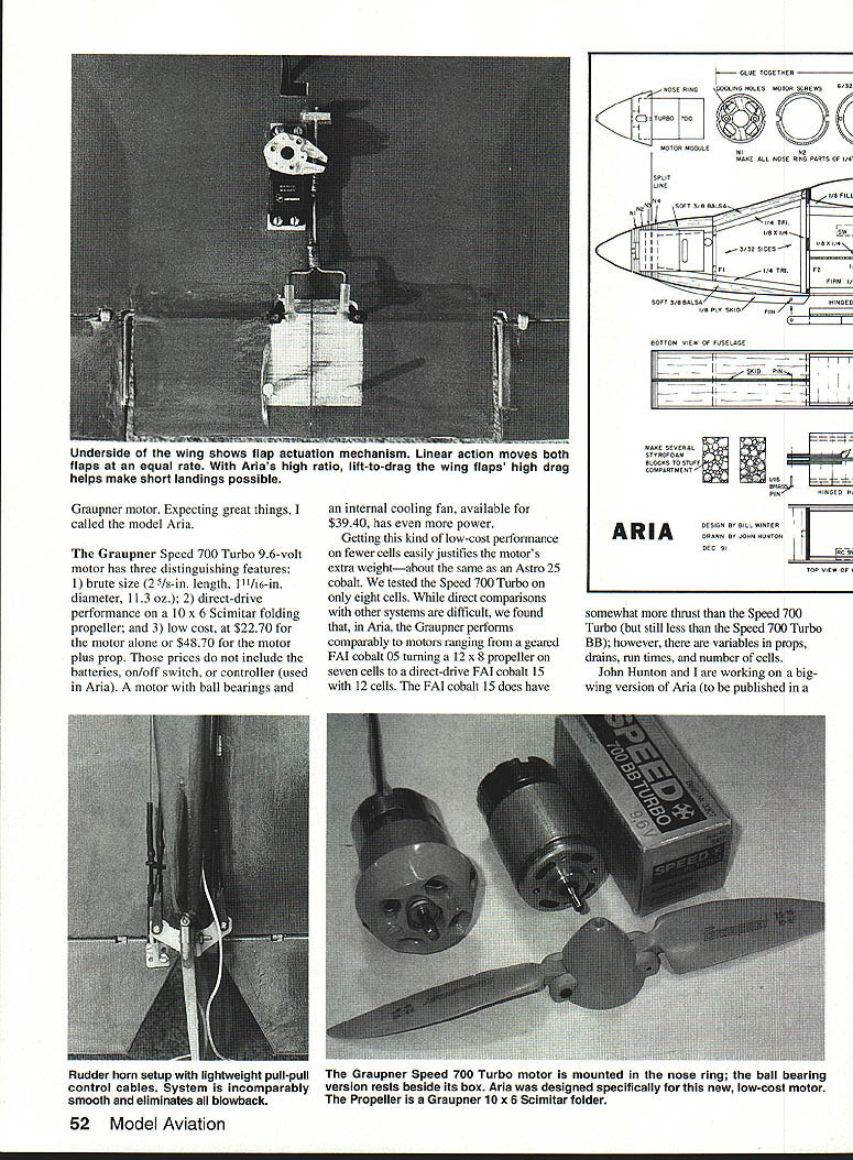
The Graupner Speed 700 Turbo (9.6‑volt) has three distinguishing features:
- brute size (2 5/8-in. length, 1 11/16-in. diameter, 11.3 oz.)
- direct-drive performance on a 10 x 6 Scimitar folding propeller
- low cost ($22.70 for the motor alone or $48.70 for the motor plus prop; a ball-bearing version with internal cooling fan is available for $39.40)
Getting this kind of low-cost performance on fewer cells easily justifies the motor's extra weight—about the same as an Astro 25 cobalt. We tested the Speed 700 Turbo on eight cells. While direct comparisons with other systems are difficult, we found that, in Aria, the Graupner performs comparably to motors ranging from a geared FAI cobalt .05 turning a 12 x 8 prop on seven cells to a direct-drive FAI cobalt .15 with 12 cells. The FAI cobalt .15 does have somewhat more thrust than the Speed 700 Turbo (but still less than the Speed 700 Turbo BB); however, there are variables in props, drains, run times, and number of cells.
John Hunton and I are working on a big-wing version of Aria (to be published in a future issue). Model Aviation will use both eight- and 10-cell test results, with an accompanying comparative guide to motor performance intended as a rough frame of reference.
Sailplane-style designs are great for majestic soaring, but I prefer planes that give you more mobility and grace in tight maneuvering near the ground while still maintaining good soaring capability.
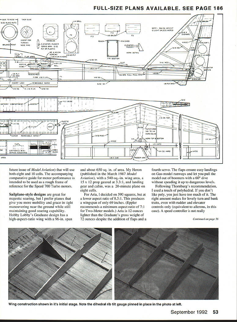
Hobby Lobby's Graduate design has a high-aspect-ratio wing with a 96-in. span and about 650 sq. in. of area. My Heron (published in March 1987 Model Aviation), with a 540-sq.-in. wing area, a 15 x 12 prop geared at 3.3:1, landing gear and cabin, was a 20-minute plane on eight cells.
For Aria, I decided on 590 sq. in. at a lower aspect ratio of 8.5:1. This produces a wingspan of only 69 inches. (Eppler recommends a minimum aspect ratio of 7:1 for two-meter models.) Aria is 12 ounces lighter than the Graduate's gross weight of 72 ounces despite the addition of flaps and a fourth servo. The flaps ensure easy landings on gas-model runways and let you pull the model out of boomers with a 60° dive without speeding it up to dangerous levels.
Following Thornburg's recommendation, I used a touch of polyhedral. If you don't like poly, you probably used too much of it. The right amount makes for lovely turn-and-bank traits, even with rudder and elevator controls only (equivalent to ailerons in this case). A speed controller is not really necessary.
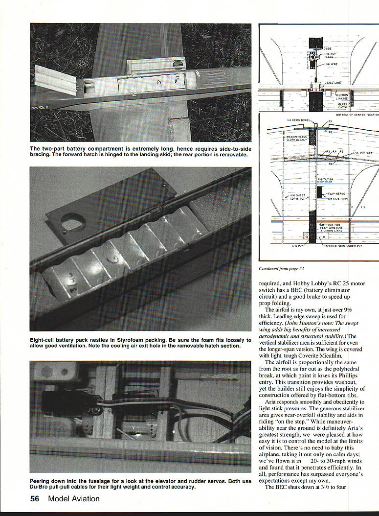
The airfoil is my own, at just over 9% thick. Leading-edge sweep is used for efficiency. (John Hunton's note: The swept wing adds big benefits of increased aerodynamic and structural stability.) The vertical stabilizer area is sufficient for even the longer-span version. The wing is covered with light, tough Coverite Micafilm.
The airfoil is proportionally the same from the root as far out as the polyhedral break, at which point it loses its Phillips entry. This transition provides washout, yet the builder still enjoys the simplicity of construction offered by flat-bottom ribs.
Aria responds smoothly and obediently to light stick pressures. The generous stabilizer area gives near-overkill stability and aids in riding "on the step." While maneuverability near the ground is definitely Aria's greatest strength, we were pleased at how easy it is to control the model at the limits of vision. There's no need to baby this airplane and take it out only on calm days; we've flown it in 20- to 30-mph winds and found that it penetrates efficiently. In all, performance has surpassed everyone's expectations except my own.
The BEC (battery eliminator circuit) shuts down after about 3½ to 4 minutes of continuous maximum power (with the model at fly‑speck height), so for the optional interchangeable 99‑in.-span wing, 10 cells is a breathtaking possibility without too much loss in power‑on time. With the 1.2‑Ah battery pack, you won't get unlimited soaring after BEC shutdown. (We end our flights 15 minutes after powering off.) Smaller cells on a BEC could be even more critical if the servos are used repeatedly.
For protracted soaring, use an independent battery pack of 250 mAh on the standard Aria and as high as 500 mAh on the long‑wing version. The battery compartment can handle 1.4‑Ah, 1.5‑Ah, and even 1.7‑Ah packs, which will boost power and glide times. Folks interested in one peak climb may opt for smaller 800‑ or 900‑mAh cells to save weight.
The system provides variable flaps and throttle on a four-channel setup. We used the Airtronics Vanguard RC system with miniservos and a 991 receiver, adding a Graupner 25 on/off motor controller. The excellent Airtronics MA-16 controller is recommended if variable power is desired. These systems are compatible with the low-cost philosophy of the Aria design.
A cable control system is used for elevator and rudder because it's simple and lightweight. Cable controls also give the pilot excellent feel and feedback.
Aria also has motor downthrust to smooth the transition between power and glide. Though it's hidden because the motor is aligned with the fuselage, this downthrust is created by the positive angle of the wing and stabilizer with respect to the motor and the fuselage. This arrangement also seems to help reduce drag in glide and improve controllability. Be sure to maintain these angular differences accurately as shown on the plan.
Hunton and I decided to provide a long-wing option with a 99-in. wingspan and 840 sq. in. of wing area. That's almost 200 additional squares, yet gross weight is still well under that of the Graduate. We used polyhedral in this version, too. The plan for the wing, together with comments on performance differences, will appear in a future issue.
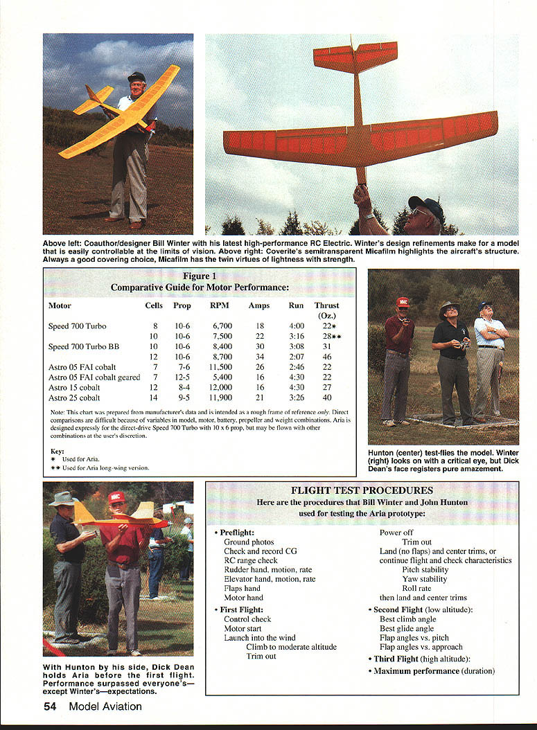
Comparative Guide for Motor Performance (Figure 1)
Note: This chart was prepared from manufacturer's data and is intended as a rough frame of reference only. Direct comparisons are difficult because of variables in model, motor, battery, propeller and weight combinations. Aria is designed expressly for the direct-drive Speed 700 Turbo with 10 x 6 prop, but may be flown with other combinations at the user's discretion.
- Speed 700 Turbo — Cells: 8; Prop: 10x6; RPM: 6,700; Amps: 18; Run: 4:00; Thrust: 22 oz. (* Used for Aria)
- Speed 700 Turbo BB — Cells: 10; Prop: 10x6; RPM: 7,500; Amps: 22; Run: 3:16; Thrust: 28 oz. (** Used for Aria long-wing version)
- Speed 700 Turbo — Cells: 10; Prop: 10x6; RPM: 8,400; Amps: 30; Run: 3:08; Thrust: 31 oz.
- Speed 700 Turbo — Cells: 12; Prop: 10x6; RPM: 8,700; Amps: 34; Run: 2:07; Thrust: 46 oz.
- Astro .05 FAI cobalt — Cells: 7; Prop: 7x6; RPM: 11,500; Amps: 26; Run: 2:46; Thrust: 22 oz.
- Astro .05 FAI cobalt (geared) — Cells: 12; Prop: 7x5; RPM: 5,400; Amps: 16; Run: 4:30; Thrust: 22 oz.
- Astro .15 cobalt — Cells: 12; Prop: 8x4; RPM: 12,000; Amps: 16; Run: 4:30; Thrust: 27 oz.
- Astro .25 cobalt — Cells: 14; Prop: 9x5; RPM: 11,900; Amps: 21; Run: 3:26; Thrust: 42 oz.
Key: * Used for Aria. ** Used for Aria long-wing version.
Flight Test Procedures
Here are the procedures Bill Winter and John Hunton used for testing the Aria prototype.
- Preflight:
- Ground photos
- Check and record CG
- RC range check
- Rudder: hand, motion, rate
- Elevator: hand, motion, rate
- Flaps: hand check
- Motor: hand check
- First Flight:
- Control check
- Motor start
- Launch into the wind
- Climb to moderate altitude
- Trim out
- Power off
- Trim out for glide
- Land (no flaps) and center trims, or continue flight and check characteristics
- Pitch stability
- Yaw stability
- Roll rate
- Land and center trims
- Second Flight (low altitude):
- Best climb angle
- Best glide angle
- Flap angles vs. pitch
- Flap angles vs. approach
- Third Flight (high altitude):
- Maximum performance (duration)
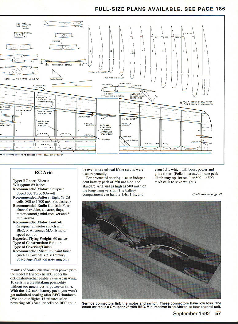
RC Aria — Specifications
- Type: RC sport electric
- Wingspan: 69 inches
- Recommended Motor: Graupner Speed 700 Turbo 9.6-volt
- Recommended Battery: Eight Ni‑Cd cells, 800 to 1,700 mAh (as desired)
- Recommended Radio Control: Four-channel (rudder, elevator, flaps, motor control); mini-receiver and three mini-servos
- Recommended Motor Control: Graupner 25 motor switch with BEC, or Airtronics MA-16 motor speed control
- Expected Flying Weight: 60 ounces
- Type of Construction: Built-up
- Type of Covering/Finish: Micafilm; paint finish (such as Coverite's 21st Century Space Age Paint) on nose ring only
Now let's get on with the construction
By John Hunton
In Aria, Bill Winter has combined European and American practice with a model that requires higher velocities than typical floaters. Experiment with your Aria to find the best velocity for highest lift-to-drag ratio or best sink rate.
Using the Airtronics Vanguard four-channel system for electrics, we set up our prototype this way:
- Right stick:
- Side-side: rudder
- Fore-aft: elevator
- Left stick:
- Side-side: no function
- Fore-aft: flap (low throttle is flaps extended; high throttle is flaps up. Motor on/off on throttle trim.)
Launch:
- Keep the flaps down for throttle safety.
- Turn on the motor power and RC system switches.
- For self-launch, set half-up elevator trim to improve the transition to climb.
- Go to high throttle (flaps will be almost up), then high-throttle trim (flaps full-up) to turn the motor on.
- Launch into the wind. Don't let the model climb up and stall. Make a smooth transition from launch to climb. Bleed off the trim as climb is established (approximately 20°, depending on wind and temperature).
- If the model is climbing cleanly, accept that climb angle. Don't force a nose-high attitude; you'll sacrifice altitude and shorten the motor run.
Climb:
- Establish the climb into the wind. Trim out the model and stay off the controls as much as possible—every input increases drag.
- If a turn is necessary, make it wide. Work the model into the wind so you can thermal later.
- When you've climbed to a comfortable altitude, shut the motor down. Keep track of motor-on time.
Glide:
- With power off, Aria transitions to a relatively fast, wind-penetrating glide.
- For thermalling, the glide must be slowed somewhat but not excessively. For a simple glider transition, add partial flaps; no trim change will be necessary.
- For best sink ratio, use quarter-flaps (≈15°) and add up trim to slow the model. If the plane appears near stall, reduce up trim or reduce flap and re-establish a smooth glide above stall velocity.
- To power up again, go to full-up flaps, then high throttle trim. (With our arrangement, power won't come on with partial flaps deployed.)
Thermalling and boomers:
- Fly into the wind. When you see the model rock or rise, establish a 30° bank to circle—let the circle come with the wind.
- If you get hooked into a boomer and want to come down quickly, go to full flaps. Aria will dive at approximately 45° with flaps full-down. If the boomer is really strong, add full down elevator trim. Aria will go into a 60° dive without danger of overspeed, flutter, or overstress, but a smooth pullout is essential—yanking it out could pull too many Gs.
Landing:
- Make a conventional, power-off approach with the motor off. Keep sufficient power reserve for a go-around or two.
- Remove any up trim so the model won't slow down too much. On final, put on full flaps for drag.
- If you're grossly too high, climb and make a 360° turn to lose 10–20 feet. Otherwise, fly the model down to the runway; with flaps deployed, speed won't build up excessively.
- Don't try to stall it in (many people do this) and then overshoot without flaps.
- For glider or electric model landings, always fly the model onto the ground—ground contact equals drag, and grass especially will slow you quickly. Stay on rudder until the model stops.
(Editor's note: Flight results with the more powerful Speed 700 Turbo ball-bearing motor using various numbers of cells will appear in a later issue. Plans for the long-wing specialized soaring version of Aria—same airframe otherwise—will be presented along with flight evaluation.)
Construction
Construction is basically typical, featuring a semi D-tube wing and box-beam fuselage. Having no ailerons to build or rig simplifies the work considerably. Because the flaps are actuated from inside the fuselage, they're relatively easy to contend with.
For the long-wing version, the absence of ailerons facilitates removal of the wing's tip panels. Our method for removing tip panels is unusual: leave the center spar joint uninterrupted (the joint that bears the greatest load) and make the tip joints the removable ones. Tip joints bear much smaller loads, so this results in lighter weight structure overall.
You can order balsa wood in bulk from several sources. We use L & L for selected lightweight wood for all applications except fuselage longerons and empennage spars—for those, use medium-hard balsa—and the spruce wing spars.
After years of building with cyanoacrylate (CYA), I developed an allergy. My nose runs for several hours after using CYA. Switching to Hot Stuff and other adhesives solved the problem. If you have allergy problems, try UFO glue. The curing rate is slightly slower, and it is easy to use.
Empennage
- Build smaller parts first; it gives more room for the larger parts.
- Build the fin with a medium-hard balsa spar and front rudder reinforcement. Use lightweight balsa for the rudder and cut lightening holes.
- Use medium-hard balsa for the horizontal stabilizer rear spar and the elevator front spar.
- Build the horizontal stabilizer but leave off the 1/4 x 3/8-in. leading edge piece. Add the top sheeting, lift the stab off the plan, and sand the front of the sheeting and ribs so they are flat. This ensures a good joint with the leading edge member when it is added.
- Finish parts with fine sandpaper on a flat block that spans at least three ribs. Sand the elevators and rudder to a straight taper.
Fuselage
- Cut nose ring and motor mounting parts (N1 through N4) from 1/4-in. aircraft plywood. Align these parts carefully for assembly.
- A convenient way of shaping the nose is to make a temporary jig to hold the assembled nose ring in a drill press, then spin the ring and shape the nose with sandpaper.
- Coat the motor with lipstick before fitting it into the nose cone. Slip the motor in and out, and remove wood where lipstick marks contact areas. Refit until the motor seats solidly.
- Install blind nuts in the rear ring (N4). This rear ring will be glued to the fuselage. Bolt the entire assembly (N1 through N4) together without the motor for fitting to the fuselage for final shaping. Parts N1 through N3 will be glued; do not glue N4 to that assembly yet.
- Cut sheet balsa sides to dimension, pin them down, and add longerons and formers. Join the sides from the nose aft. Add the bottom and then the square plywood former. Install nose ring (N4). Rough out and install nose blocks. Add top and bottom sheeting, leaving space for the battery hatch.
- Build the battery hatch and tack-glue it into place. Install wing-screw mounting blocks. Give the fuselage a final sanding, rounding off edges except at wing and stabilizer mounts. Sand nose blocks to final shape.
- To ensure accurate battery location, it is best not to position the battery until the model is completed.
Wing
- The plan shows an optional removable wing tip. If you build the tip permanently attached, apply light glass cloth over the sheeted leading edge for extra strength.
- Build wing panels as straight and true as possible. The airfoil is designed to provide critical washout at the tips yet still be built flat on the board.
- Typical panel build sequence:
- Pin down the lower spar and install bottom center and leading edge sheeting.
- Install ribs, using pins to force leading edge sheeting tight against the front of the ribs.
- Add trailing edge parts.
- Glue center sheeting panel parts in place in the panel. Wait for glue to set and lift the panel off the plan.
- Align the completed panel with the new one, pin ends to the proper dihedral, and build the second panel against the first.
- Glue center joint in place, continue building.
- After second panel reaches the same stage, add top sheeting. Use slow-setting CYA to adhere sheeting to ribs. Note the sheeting does not overlap the top spar; the spar is the outermost structural member for strength.
- When glue has set, lift the second panel, pin the first panel down, and add the top spar and sheeting to the first panel.
- When glue is fairly set, sand the front of the leading edge sheeting and ribs with a flat block. Pin the wing down again and add the 3/8 x 5/8-in. leading edge piece. This method is similar to a foam-core wing.
- Install spar web pieces. Add wing tip panels and joint details.
- Add diagonal braces (ribs 2–5). Sand wing panels with fine-grit paper on a block spanning at least three ribs.
- Apply fine glass cloth over the center section joint (top and bottom).
- Flap actuation detailing, while tedious, is necessary for linear action and ensuring flaps move at the same rate. Hinge the flaps at the bottom.
Final assembly
- Mate the wing to the fuselage before mounting the empennage. Apply strips of tape to the wing at the joint, coat the tape with lipstick, and trial fit the wing. Cut away the fuselage where lipstick shows. Repeat until lipstick marks the fuselage saddle uniformly—this is the method gunsmiths use for letting-in gun barrels to stocks.
- After the wing is seated, install the empennage using the wing for reference level. The stabilizer must not lean to either side; sight carefully so the stabilizer does not line up with the dihedral in either wing. It should be level.
- Add nose and tail skid parts after the model has been covered.
Covering
- Clean all parts carefully and vacuum. Check for bumps and "wows."
- We used Coverite Micafilm on the short-wing prototype. Micafilm is light because it has no adhesive. We used Coverite's Balsa Rite on structure where we wanted the film to adhere. These materials are easy to work with and give a good result, although they may need re-tightening with atmospheric changes.
- The long-span wing will be covered with Coverite's 21st Century Film. This film is applied differently—read the instructions carefully—but seems completely stable and hasn't needed re-tightening. We'll report more in the future long-wing article.
Finishing
- Those who like to apply finishes have only one opportunity with this aircraft: the plywood motor mount.
- For the prototype, the nose ring was primed with gray automotive primer to more or less match the Graupner propeller. Later, Coverite's 21st Century Space Age Paint spray finishes were tried. The primer fills wood pores and provides a good base for the final finish. The color coat builds well and can be reapplied quickly.
RC gear installation
- We used the Airtronics Vanguard RC system, a four-channel set packaged for electric use with a narrow-band receiver and two miniservos, but substituted a Graupner Power Switch 25 on/off motor controller since it came with the motor to be tested. A BEC is included for light weight. These systems fit the low-cost philosophy of the design.
- An excellent feature allows including both flap and motor control on the throttle stick. Low throttle and low trim provides motor-off and full flaps. Full throttle with high trim provides full motor power and flaps full-up. Adjust the controller to actuate motor-on at high throttle midway on the trim. That way you can go to flaps up, operate the motor on throttle trim, and use variable flaps on the throttle stick. This arrangement also provides a safety feature—the motor cannot be turned on unless the throttle stick is fully advanced.
- For lightweight and responsive controls, use the Du-Bro pull-pull cable kit for both elevator and rudder.
Motor wiring and batteries
- If you use the recommended Graupner 25 motor on/off switch, check the included wiring diagram for compatibility with your receiver. The receiver lead must be modified by installing a compatible connector with pin positions changed as diagrammed.
- For eight-cell operation, install a 25-amp fuse on one lead between the motor and power switch. For 10- or 12-cell operation, use a 30-amp fuse.
- We use the Dual Rapid Charger by Model Flight Accessories (available from Hobby Lobby), which recharges a fully spent eight-cell pack in about 30 minutes. Stop charging when the rate (on high rate) gets down to about an amp, or if the battery begins to feel slightly warm. With three battery packs you can have one in the air, one cooling, and one charging for continuous operations.
- Be very careful not to overcharge your batteries since this can be dangerous and can create a fire hazard.
- If you're using 10- or 12-cell motor batteries, get dual five- or six-cell flight packs. The Model Flight Accessories charger has variable charge rates and will handle these also.
Bill Winter brought 65 years of modeling experience to his latest creation. Aria can help you make a happy crossing from the world of glow power to the realm of silent flight.
Transcribed from original scans by AI. Minor OCR errors may remain.

