
ARIEL SPORT
Bob Wischer
Editor's Note
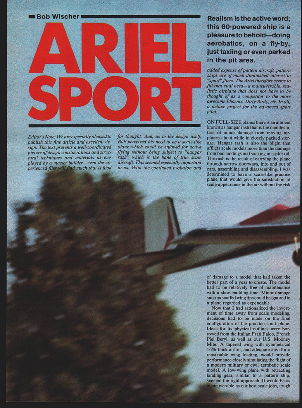
We are especially pleased to publish this fine article and excellent design. The text presents a well-coordinated picture of design considerations and structural techniques and materials as employed by a master builder—even the experienced flier will find much that is food for thought. Bob perceived his need to be a scale-like plane which could be enjoyed for active flying without being subject to "hangar rash," the bane of true scale aircraft. With the continued evolution and added expense of pattern aircraft, pattern ships are of much diminished interest to sport fliers. The Ariel therefore seems to fill that vital need—a maneuverable, realistic airplane that does not have to be thought of as a competitor to the more awesome pattern ships. In all, a deluxe project for the advanced sport pilot.
Introduction / Design Goals
Realism is the active word; this .60-powered ship is a pleasure to behold—doing aerobatics, on a fly-by, just taxiing or even parked in the pit area.
On full-size planes there is an ailment known as hangar rash, the manifestation of minor damage from moving airplanes about while in closely packed storage. Hangar rash is also the blight that afflicts scale models more than damage from bad landings and soaking in castor oil. The rash results from carrying the plane through narrow doorways, into and out of cars, and from assembling and disassembling.
I was determined to have a scale-like practice plane that would give the satisfaction of scale appearance in the air without the risk of damage to a model that had taken the better part of a year to create. The model had to be relatively free of maintenance with a short building time. Minor damage such as scuffed wingtips could be ignored in a plane regarded as expendable.
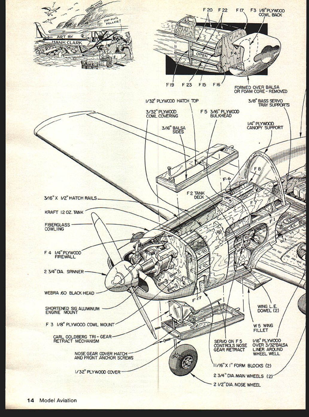
Ideas for the physical outlines were borrowed from the Italian Frati Falco, French Piel Beryl, and the U.S. Mooney Mite. A tapered wing with a symmetrical 16% thick airfoil and adequate area for reasonable wing loading would provide performance closely simulating the flight of a modern military or civil aerobatic scale model. A low-wing plane with retracting landing gear, similar to a pattern ship, seemed the right approach: maneuverable, tough enough to take a few knocks. At the sacrifice of strict scale appearance, gear doors were omitted to avoid maintenance. A large canopy encloses a scale-size pilot; miniscule pilots in tiny blister canopies spoil the scale profile of too many planes. A semi-enclosed, side-mounted engine with a cowl resembling that used on a flat engine adds character to the contour and lines. For ease of construction the plane has few curves in its external shape.
Ariel Sport was designed around a .60 engine; to keep its performance scale-like an older Webra Blackhead was used. A later Schnuerle .60 would undoubtedly improve performance and might be fitted later. There are no thrust offsets. Wing, stabilizer and engine are aligned at zero. Thick airfoiled tail surfaces, particularly the rudder, are borrowed features from Claude Piel's designs and were used because they give maximum effectiveness and smoothest handling.
Construction
Wing
- I prefer to start construction with the wing because a closer fit with the fuselage is attainable when the completed wing is at hand.
- Foam: Use white Armstrong Armalite insulation, about 1 lb/ft³. To minimize waste, cut the wing and stabilizer by the hot-wire method from a two-inch-thick foam sheet (2' x 4' standard size). Cutouts in the cores (wheel wells, servo space, long slots for retract gear pushrods) are best made with the hot wire using simple 1/16" plywood guides.
- Shallower grooves for retract mechanisms and their mounting rails are better done with a very sharp knife for outlines and digging out foam to required depth. Roughness is avoided by making all cuts with the hot wire where possible.
- Resistance wire can be bent to the exact groove shape (requires an adjustable power supply). Grooves can also be machined with a router bit or Dremel tool. Use a mechanical guide with straight edges for all foam cutting. If mounting rail slots are made too deep, fill later with epoxy; slot depth is important.
- Hardwood rails: drill and insert blind nuts for mounting retracts. Use a dummy 1/8" plywood block (same size and mounting dimensions as the retract mechanism) to hold rails parallel while epoxy hardens.
- Rails depth: If measured from the wing bottom surface both rails are same depth, the landing gear legs will slope outward due to dihedral. Set rails at different depths to compensate.
- Epoxy the rails into foam slots ensuring intimate contact with foam and wood. Hobbypoxy Thixotropic Epoxy Glue is ideal to fill unavoidable gaps without gluing mounting screws permanently into blind nuts.
- Wing skins: Edge-cement three 4" wide sheets of 3/32" balsa for each surface. Use 3/32" instead of 1/16" to permit some sanding without thinning the material severely. Select balsa carefully by weighing each sheet to find the lightest and to balance right and left wings. Mix heavier sheets between wings to avoid an unbalanced or overly heavy wing.
- Cement the prepared skins to the foam cores with a contact cement that will not dissolve foam. Add tip blocks, leading and trailing edges with white glue.
- Join wing halves on a circular saw with blade set at the dihedral angle (2 3/4°), or by hand with a sanding block. Join with epoxy.
- After carving and sanding to airfoil shape, cut-outs can be made in the top surface for servo space and bottom surfaces for wheel wells and retract mechanisms. Line openings with balsa and plywood as shown.
- Epoxy the aileron bellcrank tubes into the trailing edge fillers, then glue fillers to the wing, keeping glue from the tube ends.
- Wrap a 6" wide fiberglass cloth bandage around the wing center section and cement it with polyester resin or epoxy. Keep in mind polyester resin erodes foam—use epoxy where appropriate. The fiberglass will require sanding and blending with filler at its edges.
- Goldberg retracts: follow instruction sheet closely. The music-wire gear legs should be given a rearward set so wheels fit wells after a few hard landings. The instruction sheet specifies a small hole for the operating pushrod. The pushrod drawing calls for full tapering; a depth slot is needed for assembly.
Ailerons
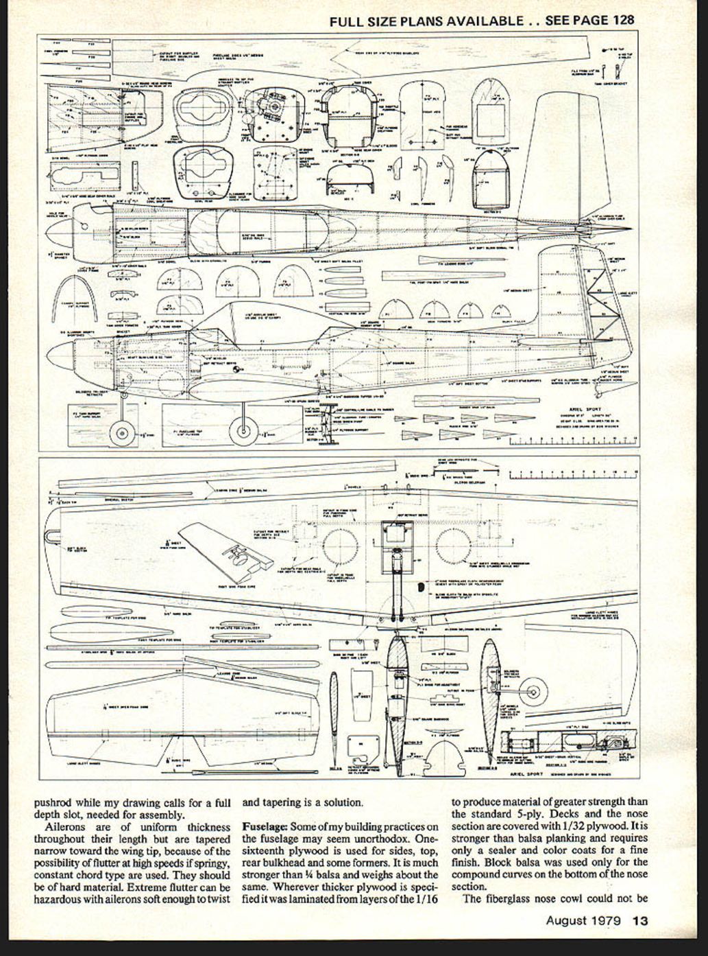
- Make ailerons of uniform thickness throughout their length but tapered narrower toward the wing tip to reduce flutter risk at high speeds.
- Use hard material and a springy, constant-chord type. Avoid soft ailerons that are prone to twisting—extreme flutter can be hazardous.
Fuselage
- Some practices may seem unorthodox: use 1/16" plywood for sides, top and rear bulkhead; where thicker plywood is specified, laminate layers of 1/16" to produce material stronger than standard 5-ply.
- Laminate fuselage sides from 1/16" plywood and 1/8" balsa using contact adhesive. The right side has the cut-out for muffler space. Add 1/4" square balsa bracing to the fuselage rear.
- Suggested build sequence:
- Fit the 1/16" plywood fuselage top.
- Add 1/8" beveled balsa strips and bulkheads F5 and F10.
- Attach prepared fuselage sides.
- Add F2 and F4, lower balsa nose blocks, and nose formers F15 through F24 including the cover frame.
- Follow with tail post, 1/4" square cross bracing, fuselage bottom, top formers F6 through F14, 3/8" square cement strips and 1/4" square former brace.
- Make heavy paper templates for each plywood deck and nose section to ensure a good fit. Soak plywood on its outer surface with water to make it pliable, then form around formers and fasten with white glue. Use heavy rubber bands (sizes 62 & 64) to apply pressure while glue sets. Imperfect joints can be leveled later with filler (Exposolite), but ensure ply is in firm contact with formers.
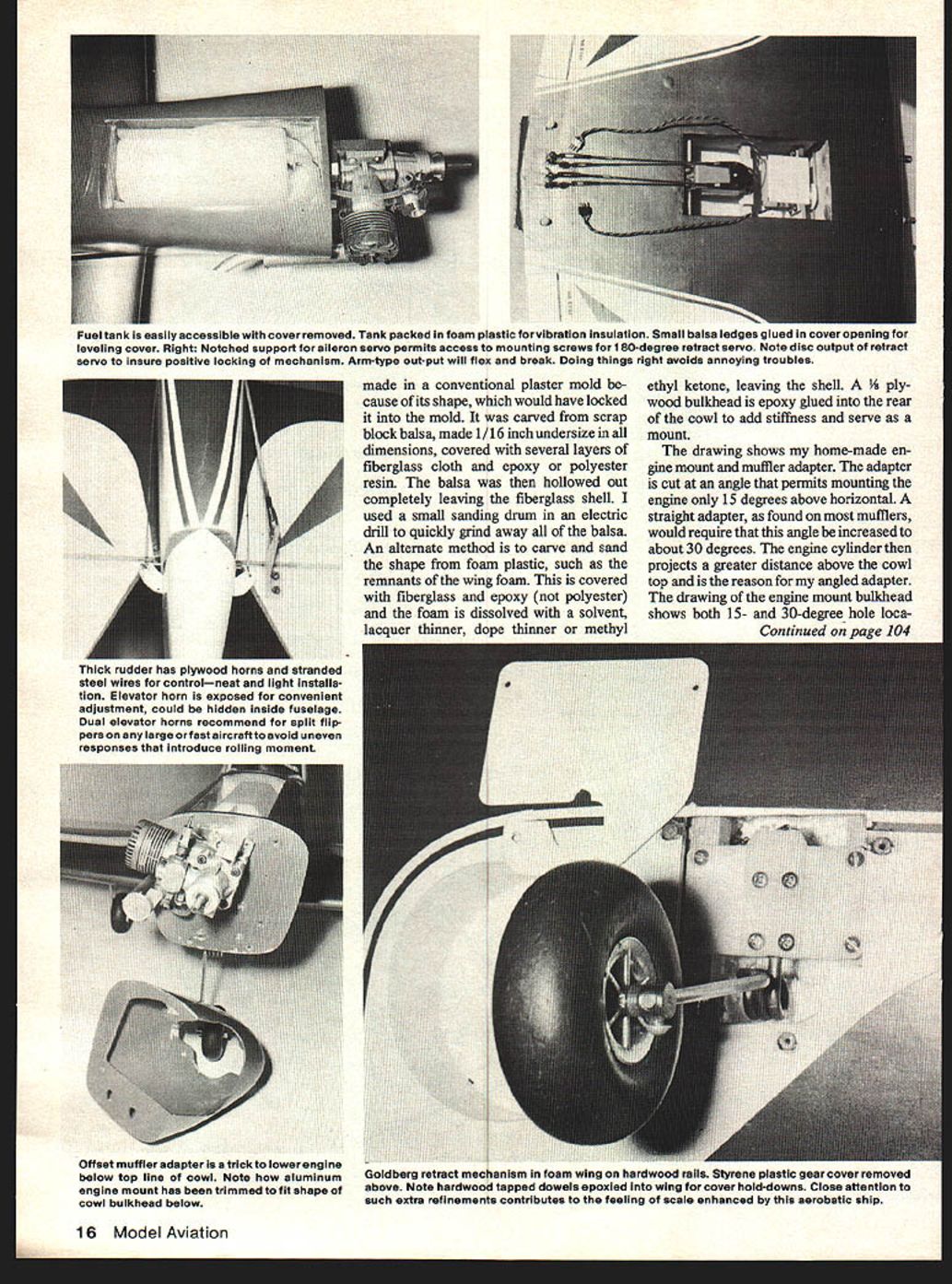
- Removable covers: Make the fuel tank and nose‑gear retract mechanism accessible with removable covers for maintenance. The Goldberg retract has been reliable once adjusted and locked per instructions. To reduce damage from broken servo output arms, consider using servo discs. Provide some means of adjusting pushrod length (a bend in the wire or a length of brass tube soldered over a break in the wire).
- Canopy: Fabricate from 1/32" acrylic (Plexiglas), stretch formed after heating in an oven to about 250°F. The windshield portion can be drape-formed over an aluminum sheet. A 15" long lighter canopy of roughly equal size is available from Sig.
Decks / Nose / Engine Cowl
- Nose section covered with 1/32" plywood. Stronger balsa planking requires sealer and color coats for a fine finish. Block balsa is used for compound curves in the bottom nose section.
- Fiberglass nose cowl methods:
- Carve a scrap block of balsa to an undersize (1/16"), cover it with several layers of fiberglass cloth and epoxy (or polyester) resin, then hollow out the balsa to leave a fiberglass shell. A small sanding drum in an electric drill speeds the hollowing.
- Alternate: carve and sand the shape in foam plastic and cover with fiberglass and epoxy. The foam can be dissolved with solvent (lacquer thinner, dope thinner or methyl ethyl ketone) to leave the shell—use epoxy with foam dissolution method, not polyester.
- Glue a 1/8" plywood bulkhead into the rear of the cowl for stiffness and as a mount.
- The drawing shows a home-made engine mount and muffler adapter. The adapter is cut at an angle permitting the engine to be mounted 15° above horizontal. A straight adapter would require about 30°, which projects the cylinder further above the cowl; the drawing shows both 15° and 30° hole locations.
Tail Surfaces
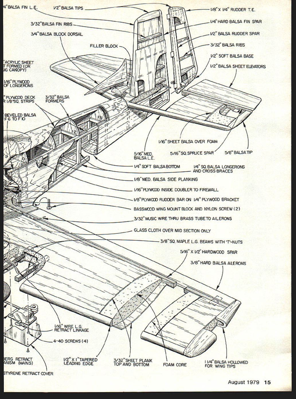
- Stabilizer: foam core cut with templates and hot-wire technique. Epoxy the foam halves at the center and cover with one continuous 1/16" balsa sheet from tip to tip for a stronger center. Add leading and trailing edges and sand to airfoil shape.
- Vertical fin: built up with ribs and covered with 1/16" balsa.
- Rudder: open-rib construction; cover with silk or plastic film to reduce weight. Rudder is operated by steel control-line cable as on many full-size planes (can be changed to a pushrod if desired).
- Elevator: controlled by a 1/4" dowel pushrod, brought out to a nylon elevator horn through the fuselage side. For improved appearance, the horn could be metal, brazed to a music wire elevator joiner at the center. If metal is used, place the clevis hole about 1" from the joiner wire.
Finishing
- I prefer silk and dope for toughness, strength and resistance to dents and scratches, though plastic film covering will work as well.
- Procedure:
- Give the complete structure three heavy brushed coats of clear dope (minimum thinner).
- Apply silk wet over all balsa surfaces (none on plywood).
- Give the silk five or six brushed coats of clear dope.
- Apply two coats of very thin dope mixed with talcum powder as filler. Balance thinner and talc: too little thinner makes the filler hard to sand; too much talc causes reticulation (cracking) and loads the sandpaper.
- Sand with 150‑grade open-coat aluminum oxide paper to remove most talc and leave pores filled but silk grain visible.
- Apply two more coats of clear to seal the talc.
- Finish with light spray color coats; keep color coats light to avoid adding weight.
- Plywood surfaces and the fiberglass cowl require minimal preparation.
Flying
- Check center of gravity carefully. My plane needed no additional weight and required no trim change on the first flight.
- Retracting the landing gear reduces drag noticeably; the plane could be converted to fixed gear if desired by substituting hardwood mounts and a standard tricycle nose gear.
- Takeoff and landing: With the nose gear length shown, a touch of up elevator at takeoff speed lifts the nose gracefully without tendency to jump. On landing, feed up elevator gradually so touch-down is on the rear wheels first, reducing speed and impact and avoiding wing-tip drop.
- Recommended control surface travel (each side of center):
- Elevator: 11/16"
- Aileron: 3/16"
- Rudder: 1 1/2"
- The low elevator and aileron travel contribute to smooth handling. With the aileron travel indicated the plane will do an axial roll in less than two seconds. Wide rudder travel is useful for stall turns. Spins and snap-roll maneuvers are positive in both entry and recovery. In inverted flight a bit of down elevator must be held.
Installation Notes
- Goldberg retracts require close attention to their instruction sheet. The wire gear legs should be bent rearward to ensure wheel fit after hard landings. The operating pushrod requires a small hole; the pushrod drawing calls for full tapering and a depth slot for assembly.
- Servo and pushrod considerations: install the retract servo rear of the first bulkhead (Carl Goldberg installation), use a direct connecting rod between steering pushrod alongside, and consider adding a means to adjust pushrod length. For nose gear, a hatch and front anchor screws will ease access.
- Reinforcement: epoxy bellcrank tubes, plywood doubler to firewall, and 3/8" square maple landing-gear beams with T-nuts are used where noted.
Materials, Parts and Construction Details
- 1/4" balsa fin leading edge
- 1/2" balsa tips
- 3/32" balsa fin ribs
- 3/4" balsa dorsal block
- Filler block
- 1/8" x 1/4" rudder trailing edge
- 1/4" hard balsa fin spar
- 1/2" balsa rudder spar
- 3/32" balsa ribs
- 1/2" soft balsa base
- 1/2" balsa sheet elevators
- 1/16" balsa sheet over foam (wing skins)
- 5/16" medium balsa leading edge
- 5/16" square spruce spar
- 5/8" balsa tip
- 1/4" soft balsa bottom
- 1/4" square balsa longerons and cross braces
- 1/8" medium balsa side planking
- 1/16" plywood inside doubler to firewall
- 1/8" plywood rudder bar on 1/4" plywood bracket
- Basswood wing mount block and nylon screw (2)
- 3/32" music wire through brass tube to ailerons
- Glass cloth over mid-section only
- 3/8" square maple landing-gear beams with T-nuts
- 5/16" x 1/2" hardwood spar
- 3/8" hard balsa ailerons
- 1/16" wire landing-gear retract linkage
- 4-40 screws (4)
- 1/2" x 1" tapered leading edge
- 3/32" sheet planking top and bottom
- Foam core
- 1 1/4" balsa hollowed for wing tips
- 3/32" balsa formers
- Beveled balsa F6 to F10
- Acrylic sheet formed (or Sig canopy)
- 1/16" plywood of longerons
- 1/32" plywood nose cover and hatch top
- 3/32" plywood cowl covering
- 3/16" balsa sides
- F5: 3/16" plywood bulkhead
- F4: 1/4" plywood firewall
- F3: 1/8" plywood cowl mount
- F2: tank deck
- 3/8" basswood servo tray supports
- 1/4" plywood canopy support
- 3/16" x 1/2" hatch rails
- Kraft 12 oz. tank
- Fiberglass cowling
- 2 3/4" diameter spinner
- Webra .60 Blackhead engine (or equivalent)
- Shortened SIG aluminum engine mount
- Carl Goldberg tri‑gear retract mechanism
- Nose gear cover hatch and front anchor screws
- 1/16" plywood over 3/32" balsa liner around wheel well
- 11/16" x 1" form blocks (2)
- 2 3/4" diameter main wheels (2)
- 2 1/2" diameter nose wheel
- Wing leading-edge dowels (2)
- W5 wing fillet
Tailoring and Tips
- Keep glue out of tube ends when installing bellcrank tubes.
- Use a mechanical guide for foam routing and a very sharp knife for shallow slots.
- If using polyester resin on foam, take precautions as it erodes foam—epoxy is preferable for foam contact.
- Balance wing sheets to avoid a heavy wing; avoid putting the six heaviest sheets all on one wing.
- Consider converting to fixed gear if maintenance or simplicity is preferred.
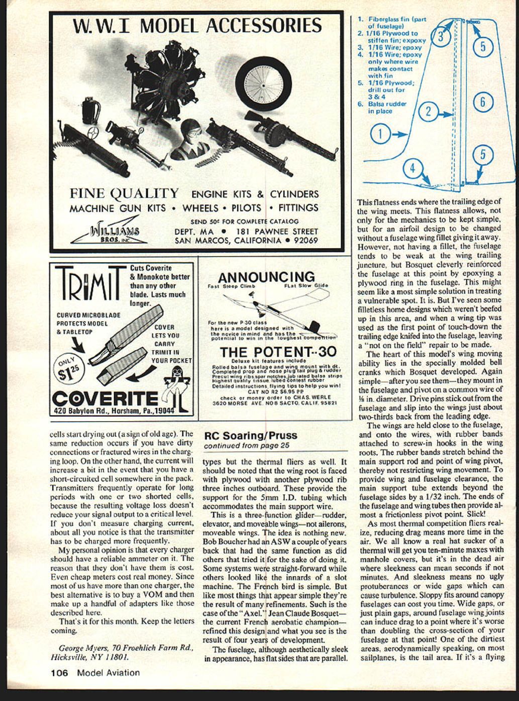
Photos / Illustrations (descriptions)
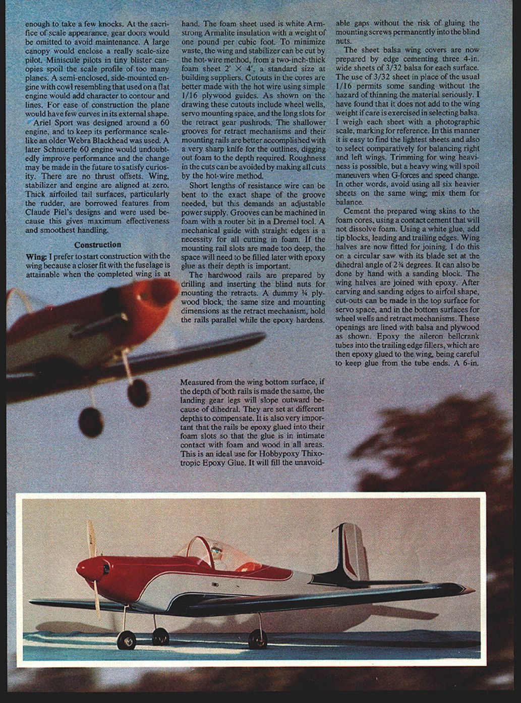
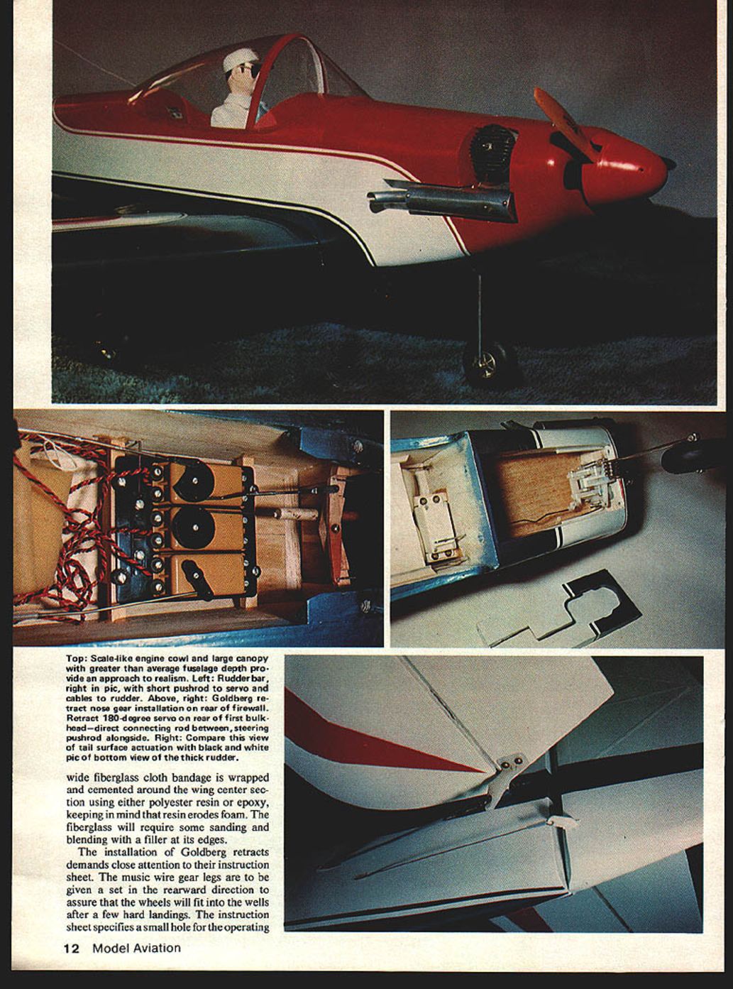
- Top: Scale-like engine cowl, large canopy, greater average fuselage depth provide approach realism.
- Left: Rudder bar; right: short pushrod, servo cables, rudder.
- Above right: Goldberg retract nose gear installation, rear firewall. Retract 180-degree servo rear of first bulkhead; direct connecting rod between steering pushrod alongside.
- Right: Comparison view of tail surface actuation.
- Bottom view: Thick rudder; wide fiberglass cloth bandage wrapped and cemented around wing center section. Keep in mind resin erodes foam; fiberglass will require sanding and blending filler at its edges.
I really enjoy flying Ariel Sport and think you will too.
Transcribed from original scans by AI. Minor OCR errors may remain.

