
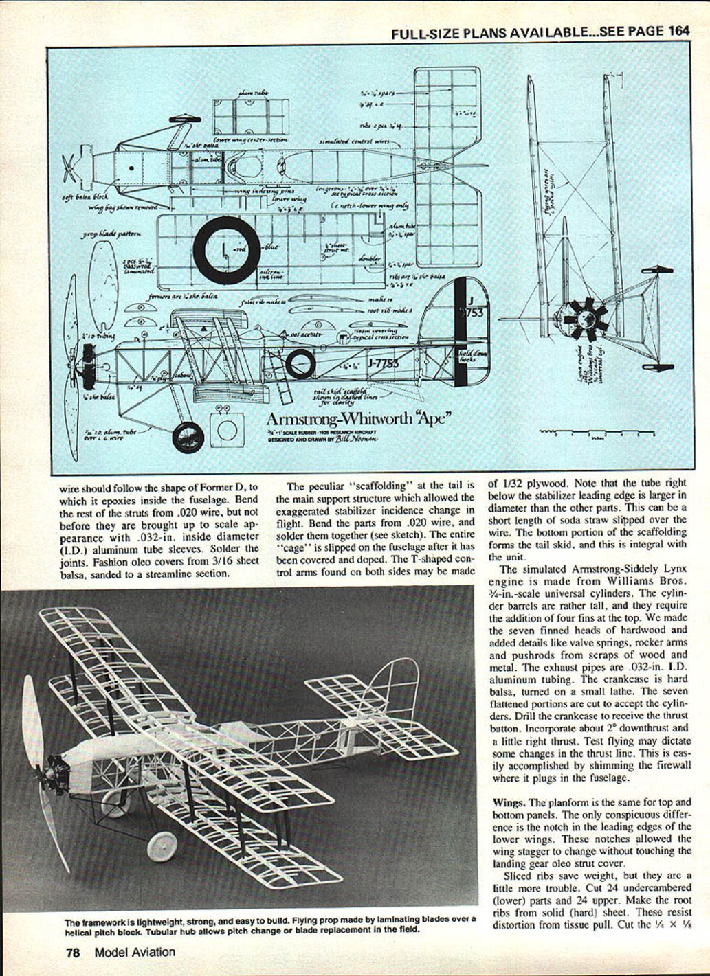
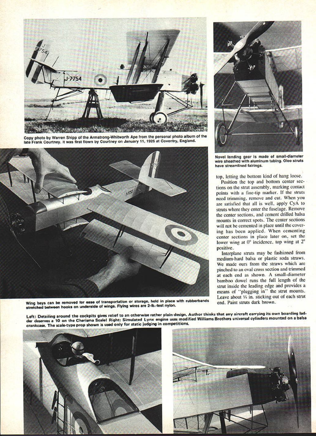
Armstrong-Whitworth "Ape"
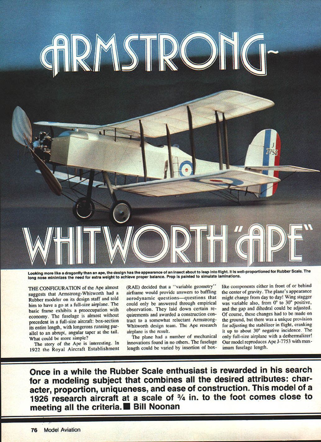
Looking more like a dragonfly than an ape, the design has the appearance of an insect about to leap into flight. It is well‑proportioned for rubber scale: the long nose minimizes the need for extra weight to achieve proper balance. (Prop painted to simulate laminations.)
The configuration and history
The Ape almost suggests that Armstrong‑Whitworth had a rubber‑modeler on its design staff and told him to have a go at a full‑size airplane. The basic frame exhibits a preoccupation with economy: the fuselage is box‑section its entire length, with longerons running parallel to an abrupt, angular taper at the tail.
In 1922 the Royal Aircraft Establishment (RAE) decided that a "variable‑geometry" airframe would provide answers to baffling aerodynamic questions that could only be resolved empirically. They laid down certain requirements and awarded a construction contract — somewhat reluctantly — to an Armstrong‑Whitworth design team. The Ape research airplane was the result.
The plane incorporated a number of mechanical innovations found in no other contemporary type:
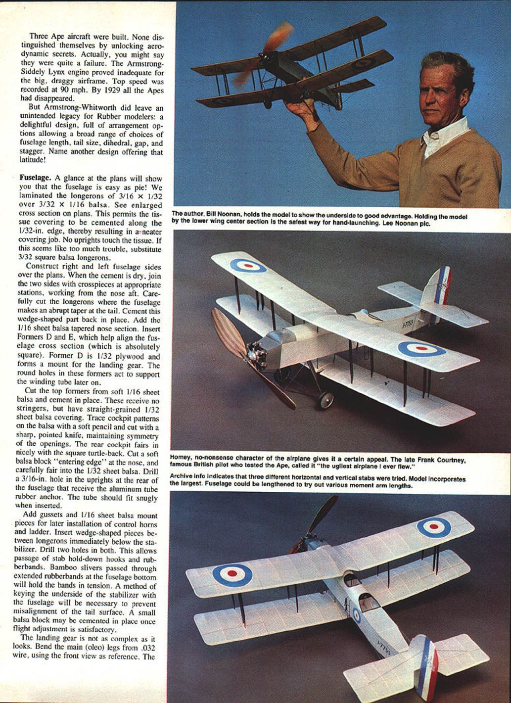
- Fuselage length could be varied by insertion of boxlike components either in front of or behind the center of gravity — the plane's appearance could change from day to day.
- Wing stagger was adjustable from 0° to 30° positive.
- Gap and dihedral could be changed (on the ground).
- The stabilizer had a unique provision for adjustment in flight, up to about 30° negative incidence — the only full‑size airplane with a dethermalizer.
The model reproduces Ape J‑7753 with maximum fuselage length.
Three Ape aircraft were built. None unlocked the anticipated aerodynamic secrets: the Armstrong‑Siddeley Lynx engine proved inadequate for the big, draggy airframe and top speed was only about 90 mph. By 1929 all the Apes had disappeared. Armstrong‑Whitworth did, however, leave an unintended legacy for rubber modelers — a delightful design offering broad choices of fuselage length, tail size, dihedral, gap, and stagger.
Fuselage
At a glance the fuselage is straightforward. Laminate the longerons from 3/16 x 1/32 over 3/32 x 1/16 balsa (see enlarged cross section on plans). This permits the tissue covering to be cemented along the 1/32‑in. edge for a neater job. If this seems too fussy, substitute 3/32‑in. square balsa longerons.
Construction sequence:
- Construct right and left fuselage sides over the plans.
- When cement is dry, join the two sides with crosspieces at the appropriate stations, working from the nose aft.
- Carefully cut the longerons where the fuselage makes an abrupt taper at the tail and cement the wedge‑shaped part back in place.
- Add the 1/16‑in. sheet balsa tapered nose section.
- Insert formers D and E to align the fuselage cross section; Former D is 1/32‑in. plywood and forms a mount for the landing gear. Round holes in these formers support the winding tube later on.
Cut the top formers from soft 1/16‑in. sheet balsa and cement in place. These receive no stringers but have straight‑grained 1/32‑in. sheet balsa covering. Trace cockpit patterns on the balsa with a soft pencil and cut with a sharp knife, maintaining symmetry of the openings. The rear cockpit fairs nicely into a square turtleback. Cut a soft balsa block for the nose "entering" edge and fair it into the 1/32‑in. sheet balsa.
Drill a 3/16‑in. hole in the uprights at the rear of the fuselage to receive the aluminum tube rubber anchor; the tube should fit snugly. Add gussets and 1/16‑in. sheet balsa mount pieces for later installation of control horns and the ladder. Insert wedge‑shaped pieces between the longerons immediately below the stabilizer and drill two holes to allow passage of stab hold‑down hooks and rubber bands.
Keying and rubber retention:
- Bamboo slivers passed through extended rubber bands at the fuselage bottom will hold the bands under tension.
- A method of keying the underside of the stabilizer to the fuselage is necessary to prevent misalignment; a small balsa block may be cemented in place once flight adjustments are satisfactory.
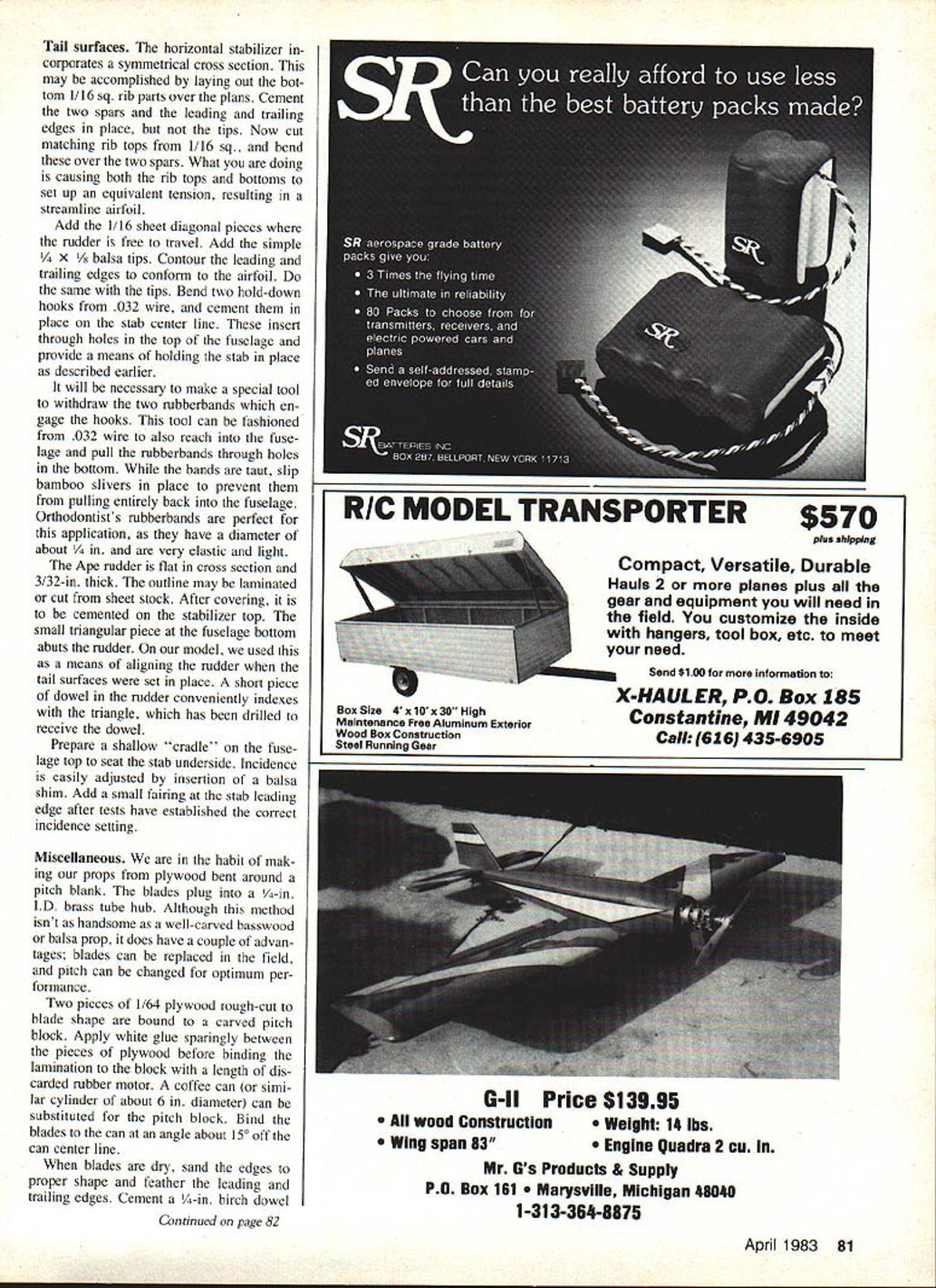
Landing gear and tail scaffolding
Landing gear:
- Bend the main (oleo) legs from .032‑in. wire, using the front view on the plans as reference. The wire should follow the shape of Former D and is epoxied inside the fuselage.
- Bend the rest of the struts from .020‑in. wire, and dress them to scale appearance with .032‑in. I.D. aluminum tube sleeves. Solder the joints.
- Fashion oleo covers from 3/16‑in. sheet balsa sanded to a streamlined section.
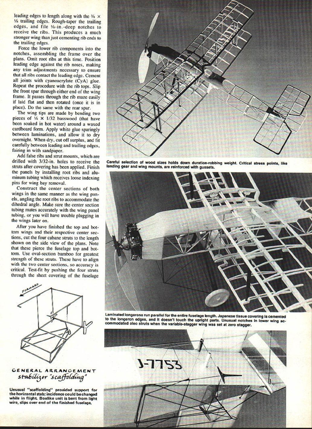
Tail scaffolding:
- The peculiar scaffolding at the tail is the main support structure that allowed the exaggerated stabilizer incidence change in flight. Bend the parts from .020‑in. wire and solder together. The entire "cage" slips on the fuselage after covering and doping.
- T‑shaped control arms may be made from 1/32‑in. plywood. Note the tube below the stabilizer leading edge is larger in diameter than the others; a short length of soda straw slipped over the wire will simulate this.
- The bottom portion of the scaffolding forms the tail skid and is integral with the unit.
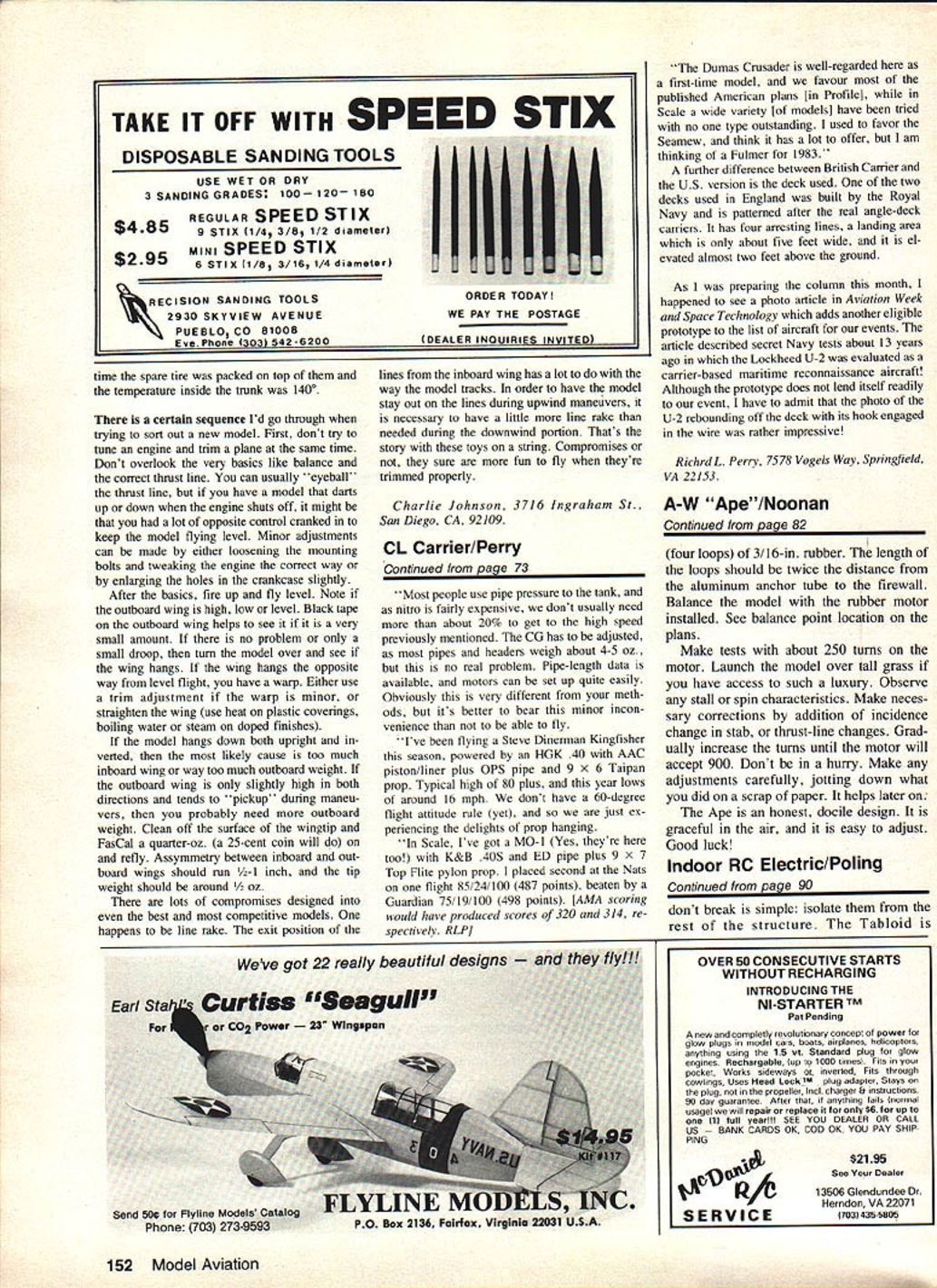
Engine and firewall
Simulated Armstrong‑Siddeley Lynx:
- Use Williams Bros. 1/4‑in.‑scale universal cylinders. Cylinder barrels may be tall; add four fins at the top.
- Make seven finned heads from hardwood and add details like valve springs, rocker arms and pushrods from scraps of wood and metal.
- Exhaust pipes are .032‑in. I.D. aluminum tubing.
- Turn the crankcase from hard balsa on a small lathe; cut seven flattened portions to accept the cylinders and drill to receive the thrust button.
Incorporate about 2° downthrust and a little right thrust. Test flying may dictate thrust‑line changes; these are easily accomplished by shimming the firewall where it plugs into the fuselage.
Wings
The planform is the same for top and bottom panels; the only conspicuous difference is a notch in the leading edges of the lower wings to allow wing stagger changes without touching the landing gear oleo strut cover.
Ribs and spars:
- Sliced ribs save weight but require more work. Cut 24 undercambered (lower) parts and 24 upper parts. Make the root ribs from solid (hard) sheet to resist distortion from tissue pull.
- Cut 1/4 x 1/8 spar cap strips and leading edges to length, along with 3/8 x 1/8 trailing edges. Rough‑taper the trailing edges and file 1/8‑in.‑deep notches to receive the ribs — a much stronger method than just cementing rib ends to the trailing edge.
Assembly:
- Force the lower rib components into the notches, assembling the frame over the plans. Omit root ribs at this time.
- Position the leading edge against the rib noses, trim as necessary to ensure all ribs contact the leading edge. Cement all joints with cyanoacrylate (CyA) glue.
- Repeat with the rib tops.
- Slip the front spar through either end of the wing frame (lay flat and rotate once in place), then do the same with the rear spar.
Wing tips:
- Make tips by laminating two pieces of 1/8 x 1/32 basswood (soaked in hot water) around a waxed cardboard form. Use white glue sparingly between laminations and dry overnight. Trim and fair to leading and trailing edges.
Finish:
- Add false ribs and strut mounts, drilling them with 3/32‑in. holes to receive the struts after covering.
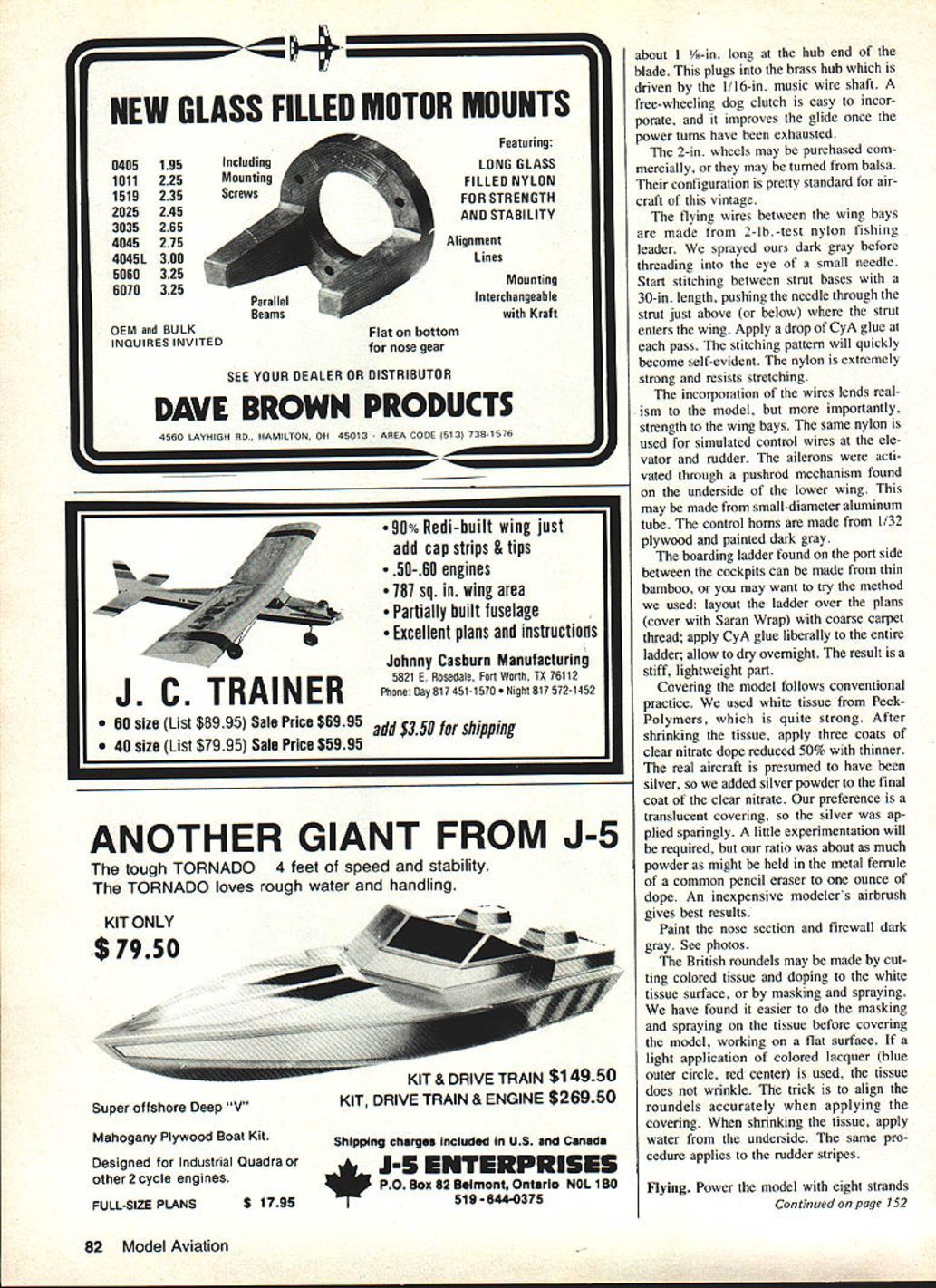
- Install root ribs and aluminum tubing which receives loose indexing pins for wing bay removal.
Center sections:
- Construct center sections like the panels, angling root ribs for dihedral. Ensure center section tubing mates accurately with wing panel tubing to avoid plug‑in problems.
Cabane and interplane struts:
- Cut four cabane struts to the lengths shown on the plans. These pierce the fuselage top and bottom. Use oval‑section bamboo for strength. Accuracy is critical.
- Test‑fit by pushing the four struts through the sheet covering of the fuselage top, letting the bottom hang loose. Position the top and bottom center sections on the strut assembly and mark contact points; trim as necessary. Apply CyA to struts where they enter the fuselage, remove center sections, and cement drilled balsa mounts in correct spots. Center sections are not permanently cemented until after covering; when cemented later, set the lower wing at 0° incidence and the top wing at 2° positive.
- Interplane struts may be made from medium‑hard balsa or plastic soda straws (ovalized). A small‑diameter bamboo dowel runs the full length of the strut inside the leading edge and provides a plug‑in method. Leave about 1/8 in. protruding at each strut end. Paint struts dark brown.
Tail surfaces
Horizontal stabilizer:
- The stabilizer uses a symmetrical cross section. Lay out the bottom 1/16‑in. square rib parts over the plans, cement two spars and the leading and trailing edges in place (but not the tips). Cut matching rib tops from 1/16‑in. square and bend them over the two spars so rib tops and bottoms set up equivalent tension, resulting in a streamlined airfoil.
- Add 1/16‑in. sheet diagonal pieces where the rudder is free to travel. Add 1/4 x 1/8 balsa tips and contour leading and trailing edges to conform to the airfoil.
Hold‑down and indexing:
- Bend two hold‑down hooks from .032‑in. wire and cement them in place on the stab center line. These insert through holes in the top of the fuselage and hold the stabilizer in place.
- Make a special tool from .032‑in. wire to withdraw the two rubber bands that engage the hooks; the tool can also reach into the fuselage to pull the rubber bands through holes in the bottom. While bands are taut, slip bamboo slivers in place to prevent them from pulling entirely back into the fuselage.
- Orthodontist's rubber bands (about 1/4 in. diameter) are ideal: elastic and light.
Rudder:
- The rudder is flat in cross section and 3/32‑in. thick; outline may be laminated or cut from sheet stock. After covering, cement it on the stabilizer top. A small triangular piece at the fuselage bottom abuts the rudder and can be used to align the rudder when tail surfaces are set in place; a short dowel in the rudder indexes into the drilled triangle.
Prepare a shallow cradle on the fuselage top to seat the stabilizer underside. Incidence is adjusted by inserting a balsa shim. Add a small fairing at the stab leading edge after tests establish the correct setting.
Miscellaneous construction and finishing
Propeller:
- Make props from plywood bent around a pitch block; blades plug into a 1/4‑in. I.D. brass tube hub. Two pieces of 1/64‑in. plywood rough‑cut to blade shape are bound to a carved pitch block. Apply white glue sparingly, bind the lamination to the block with a length of discarded rubber motor, and dry. A coffee can about 6 in. diameter can substitute for the pitch block if required. Bind blades at an angle about 15° off the can center line.
- When dry, sand edges to proper shape and feather leading and trailing edges. Cement a 1/4‑in. birch dowel about 1 1/8‑in. long at the hub end of the blade to plug into the brass hub driven by a 1/16‑in. music‑wire shaft. A free‑wheeling dog clutch is easy to incorporate and improves the glide once power is exhausted.
Wheels:
- 2‑in. wheels may be purchased commercially or turned from balsa. Their configuration is standard for aircraft of this vintage.
Flying wires and control rigging:
- Flying wires between wing bays are made from 2‑lb‑test nylon fishing leader. Spray the leader dark gray before threading into the eye of a small needle. Stitch between strut bases with a 30‑in. length, pushing the needle through the strut just above (or below) where the strut enters the wing. Apply a drop of CyA at each pass. The stitching pattern becomes self‑evident. The nylon is strong and resists stretching.
- Use the same nylon for simulated control wires at the elevator and rudder.
- Ailerons were activated through a pushrod mechanism under the lower wing; this may be made from small‑diameter aluminum tube. Control horns are 1/32‑in. plywood painted dark gray.
Boarding ladder:
- Make from thin bamboo or by laying out the ladder over the plans (cover with Saran Wrap), using coarse carpet thread and liberal CyA glue. Allow to dry overnight for a stiff, lightweight ladder.
Covering and finishing:
- Use a strong white tissue (we used Peck‑Polymers). After shrinking, apply three coats of clear nitrate dope reduced 50% with thinner.
- The real aircraft is presumed silver; add silver powder to the final coat of clear nitrate for a translucent silver finish. A suggested ratio is about as much powder as might be held in the metal ferrule of a common pencil eraser to one ounce of dope. An inexpensive modeler's airbrush gives best results.
- Paint the nose section and firewall dark gray.
- British roundels may be made by cutting colored tissue and doping them to the white tissue surface, or by masking and spraying. We find it easier to mask and spray the roundels on the flat tissue before covering the model. Use light colored lacquer (blue outer circle, red center) so the tissue does not wrinkle. Align roundels accurately when applying the covering. When shrinking tissue, apply water from the underside. The same procedure applies to rudder stripes.
Flying
Power the model with eight strands (four loops) of 3/16‑in. rubber. The length of the loops should be twice the distance from the aluminum anchor tube to the firewall. Balance the model with the rubber motor installed (see balance point on the plans).
Test procedure:
- Make initial tests with about 250 turns on the motor. Launch over tall grass if available.
- Observe any stall or spin characteristics and correct by changing stabilizer incidence or thrust line as required.
- Gradually increase turns until the motor will accept 900. Do not rush — make adjustments carefully and note each change.
The Ape is an honest, docile design: graceful in the air and easy to adjust. Good luck!
Transcribed from original scans by AI. Minor OCR errors may remain.

