
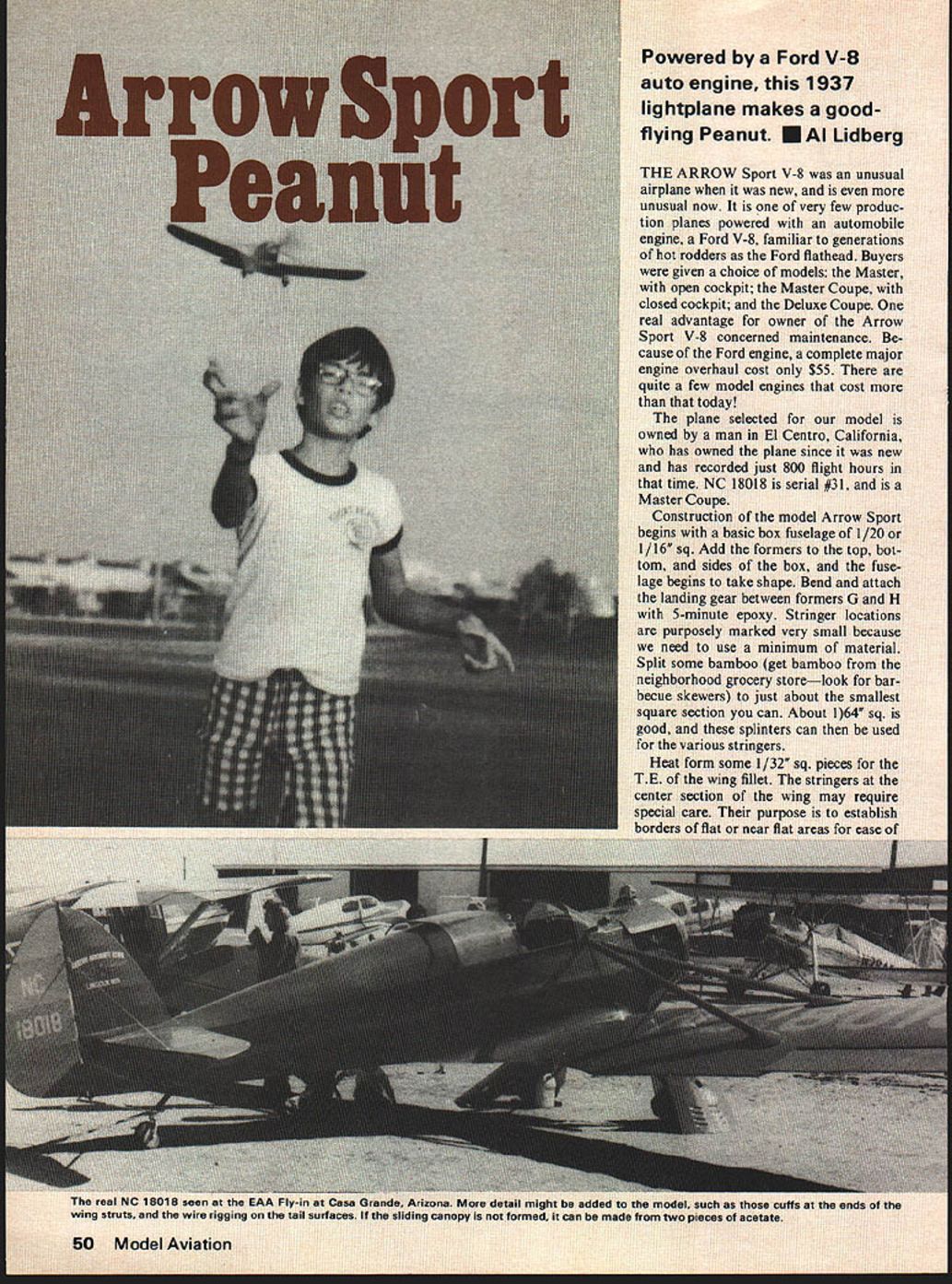
Arrow Sport Peanut
Powered by a Ford V-8 auto engine, this 1937 lightplane makes a good-flying Peanut. ■ Al Lidberg
THE ARROW Sport V-8 was an unusual airplane when it was new, and is even more unusual now. It is one of very few production planes powered with an automobile engine, a Ford V-8, familiar to generations of hot rodders as the Ford flathead. Buyers were given a choice of models: the Master, with open cockpit; the Master Coupe, with closed cockpit; and the Deluxe Coupe. One real advantage for owners of the Arrow Sport V-8 concerned maintenance. Because of the Ford engine, a complete major engine overhaul cost only $55. There are quite a few model engines that cost more than that today!
The plane selected for our model is owned by a man in El Centro, California, who has owned the plane since it was new and has recorded just 800 flight hours in that time. NC 18018 is serial #31, and is a Master Coupe.
Construction of the model Arrow Sport begins with a basic box fuselage of 1/20 or 1/16" sq. Add the formers to the top, bottom, and sides of the box, and the fuselage begins to take shape. Bend and attach the landing gear between formers G and H with 5-minute epoxy. Stringer locations are purposely marked very small because we need to use a minimum of material. Split some bamboo (get bamboo from the neighborhood grocery store—look for barbecue skewers) to just about the smallest square section you can. About 1/64" sq. is good, and these splinters can then be used for the various stringers.
Heat form some 1/32" sq. pieces for the T.E. of the wing fillet. The stringers at the center section of the wing may require special care. Their purpose is to establish borders of flat or near-flat areas for ease of covering.
For the fuselage top and wing fillets I would use numerous small pieces of tissue to cover the fillet. Make up wing struts a bit longer than shown on the plan; you'll be able to trim them to the exact length later. Leave off the tip now.
Assemble the wing panels to the body. Use 5-minute epoxy to lightly tack glue the tail surfaces in place; you'll be able to change the stabilizer angle if a major trim change is needed. Now you are ready to dope and color paint—apply a thin coat of clear nitrate dope. Cover the model before assembly with thin Japanese tissue. You'll need to spend extra time on the stringered part of the covering. Stringers No. 2 and 3 start at former H; 2 extends to former J, while 3 goes on to the next cross brace. The paper fillet goes on from there and finishes off the bottom of the center section. Add the wing mount ribs at each side of the lower formers. Using bond paper, cover back to the instrument panel, and all around the body from the nose formers to former G.
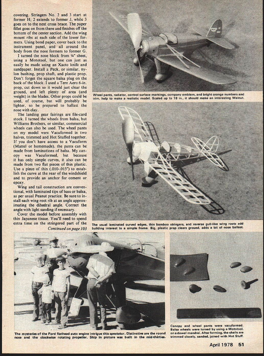
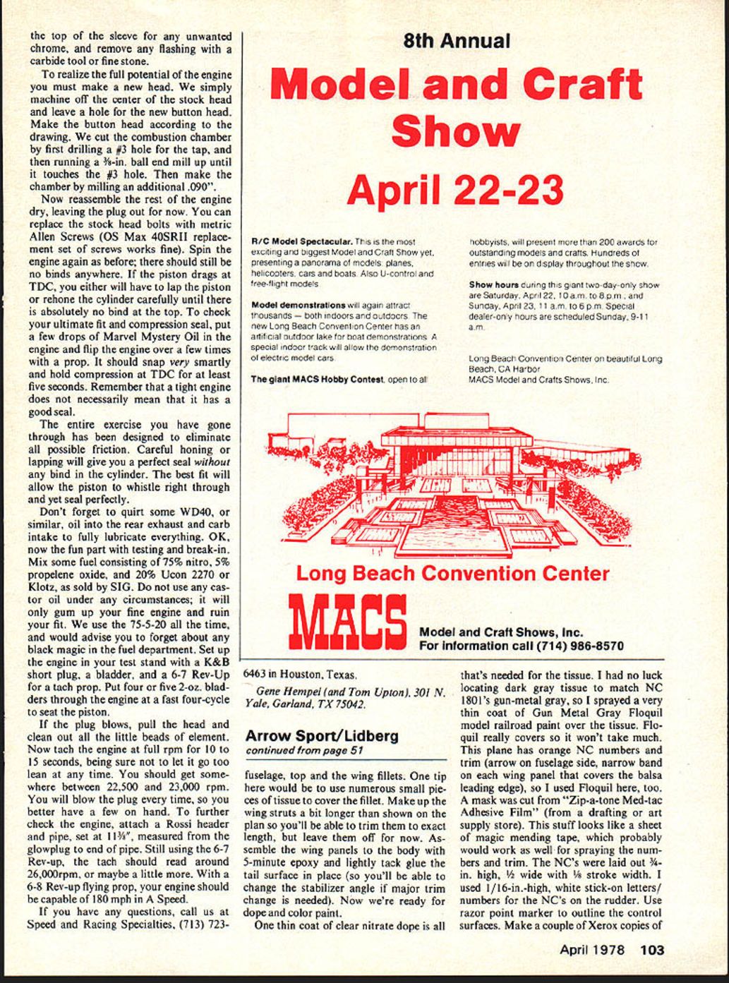
I turned the nose block from 1/4" sheet, using a Mototool, but one can just as easily be made using an Xacto knife and sandpaper. Install a Peck, or similar, nylon bushing, prop shaft, and plastic prop. Don't forget the square balsa plug on the back of the block. I used a Tern Aero 6-in. prop, cut down so it would just clear the ground, and left plenty of area (and weight) in the blades. Other props could be used, of course, but will probably be lighter, so be prepared to ballast the nose with clay.
The landing gear fairings are file-card stock. I turned the wheels from balsa, but Williams Brothers, or similar, commercial wheels can also be used. The wheel pants on my model were vacuformed in two halves, trimmed and Hot Stuffed together. If you don't have access to a vacuform (Mattel or homemade), the pants can be made from laminations of balsa. My canopy was vacuformed, but because it has only simple curves, it also can be made from two flat pieces of thin plastic. Use a piece of thin (.010-.015") to establish the curve at the rear of the windshield and to provide an anchor for cement or epoxy.
Wing and tail construction are conventional, with laminated tips of bass or balsa, as per usual Peanut practice. Be sure to install each wing root rib at an angle approximating the dihedral angle. Correct the angle with light sanding if necessary. the top of the sleeve for any unwanted chrome, and remove any flashing with a carbide tool or fine stone.
To realize the full potential of the engine you must make a new head. We simply machine off the center of the stock head and leave a hole for the new button head. Make the button head according to the drawing. We cut the combustion chamber by first drilling a #3 hole for the tap, and then running a 3/8-in. ball end mill up until it touches the #3 hole. Then make the chamber by milling an additional .090".
Now reassemble the rest of the engine dry, leaving the plug out for now. You can replace the stock head bolts with metric Allen screws (OS Max 40SRIII replacement set of screws works fine). Spin the engine again as before; there should still be no binds anywhere. If the piston drags at TDC, you either will have to lap the piston or rehone the cylinder carefully until there is absolutely no bind at the top. To check your ultimate fit and compression seal, put a few drops of Marvel Mystery Oil in the engine and flip the engine over a few times with a prop. It should snap very smartly and hold compression at TDC for at least five seconds. Remember that a tight engine does not necessarily mean that it has a good seal.
The entire exercise you have gone through has been designed to eliminate all possible friction. Careful honing or lapping will give you a perfect seal without any bind in the cylinder. The best fit will allow the piston to whistle right through and yet seal perfectly.
Don't forget to squirt some WD-40, or similar, oil into the rear exhaust and carb intake to fully lubricate everything. OK, now the fun part with testing and break-in. Mix some fuel consisting of 75% nitro, 5% propylene oxide, and 20% Ucon 2270 or Klotz, as sold by SIG. Do not use any castor oil under any circumstances; it will only gum up your fine engine and ruin your fit. We use the 75-5-20 all the time, and would advise you to forget about any black magic in the fuel department. Set up the engine in your test stand with a K&B short plug, a bladder, and a 6-7 Rev-Up for a tach prop. Put four or five 2-oz. bladders through the engine at a fast four-cycle to seat the piston.
If the plug blows, pull the head and clean out all the little beads of element. Now tach the engine at full rpm for 10 to 15 seconds, being sure not to let it go too lean at any time. You should get somewhere between 22,500 and 23,000 rpm. You will blow the plug every time, so you better have a few on hand. To further check the engine, attach a Rossi header and pipe, set at 1 13/16", measured from the glowplug to end of pipe. Still using the 6-7 Rev-Up, the tach should read around 26,000 rpm, or maybe a little more. With a 6-8 Rev-Up flying prop, your engine should be capable of 180 mph in A Speed.
If you have any questions, call us at Speed and Racing Specialties, (713) 723-6463 in Houston, Texas.
Gene Hempel (and Tom Upton), 301 N. Yale, Garland, TX 75042.
fuselage, top and the wing fillets. One tip here would be to use numerous small pieces of tissue to cover the fillet. Make up the wing struts a bit longer than shown on the plan so you'll be able to trim them to exact length, but leave them off for now. Assemble the wing panels to the body with 5-minute epoxy and lightly tack glue the tail surface in place (so you'll be able to change the stabilizer angle if major trim change is needed). Now we're ready for dope and color paint.
One thin coat of clear nitrate dope is all that's needed for the tissue. I had no luck locating dark gray tissue to match NC 1801's gun-metal gray, so I sprayed a very thin coat of Gun Metal Gray Floquil model railroad paint over the tissue. Floquil really covers so it won't take much. This plane has orange NC numbers and trim (arrow on fuselage side, narrow band on each wing panel that covers the balsa leading edge), so I used Floquil here, too. A mask was cut from "Zip-a-tone Med-tac Adhesive Film" (from a drafting or art supply store). This stuff looks like a sheet of magic masking tape, which probably would work as well for spraying the numbers and trim. The NC's were laid out 3/8-in. high, 1/16-in. white stick-on letters or numbers for the NC's on the rudder. Use razor point marker to outline the control surfaces. Make a couple of Xerox copies of the plan. Cut out the Arrow Sport emblem, darken the background a bit with pencil lead, then cut out and apply to the rudder. Checking for correct any warps, then add the struts.
Make sure the model balances just forward of the spar. Be sure the motor is in place and that the prop free-wheels before making glide tests to produce a reasonable glide; breath on, and warp, the stab or rudder as necessary. The stab also can be loosened to change its angle, if the warping isn't enough. Try low-power flights with 50-75 turns to see what happens. My model flies nicely with a degree or so of down- and right-thrust. Work up to maximum turns with a winder, and experiment with different widths and lengths of motors.
Aside from the actual airplane, NC 18018, which I have seen and photographed at an Antique fly-in, reference material on the Arrow Sport V-8 has not been easy to find. A letter to the Smithsonian produced a copy of a sales brochure, some Xerox copies of photos, and a 3-view. The 3-view actually was of the open-cockpit version, with shorter wings. A Megow rubber-motored plan is also available for the open cockpit version. It has a 23-in. span. I used these basic layouts, making changes to match NC 18018. Two magazine references showing photos of the open cockpit version are: Ford Life, Vol. 2, Issue 2 (excellent photo of plane posed with 1937 Ford car), and Air Progress, June–July 1963 (one photo on p. 68 of NC 18018).
Welcome back to fun flying — and I hope you enjoy the Arrow Sport V-8.
Transcribed from original scans by AI. Minor OCR errors may remain.

